AUTONICS光电开关
- 格式:pdf
- 大小:1.26 MB
- 文档页数:6
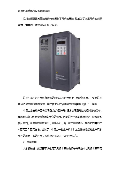
汇川变频器因其的独特的特点受到了用户的青睐,这时为了满足用户的实际需求,销售的厂家也逐渐的多了起来。
这些厂家在对产品进行报价的时候从几百元到上千元之间不等。
主要是这些原因造成的其价格不固定,用户在进行产品购买的时候需要了解:1、类型市场上出售的产品有简易型、迷你型等等。
通常简易型的结构相对比较简单,体积比较轻,但是变频作用却十分的优良。
因此这种产品的市场售价一般都在贰佰元左右。
迷你型的体积更小,迷你小巧,由于做工比较精巧,故而它的售价在4百元至5百元左右。
当然了,市场上一些生产技术和工艺比较落后的生产厂家生产的就是一般的产品,价格相对来讲在700百元左右。
2、应用领域
大家都知道,变频器可以应用于风机水泵和电机等等设备中,风机水泵所需
要的产品的结构和功能与电机所需要的产品的结构功能肯定是不同的。
这三种设备的产品的价格是根据设备的价格和品质来定的。
比如说,风机的价格比较高,故而它所需要的变频器的价格也就越高。
3、型号
该类产品的型号有很多,不同型号的产品应用领域、功能都是有所不同的,所以价格也是千差万别。
这时,想知道具体变频器售卖的用户可咨询河南科威腾电气设备有限公司进行详细的了解。
我们为客户提供台达变频器、PLC、触摸屏、开关电源、伺服系统,汇川PLC,汇川变频器,汇川伺服,汇川人机界面,台达系列产品,西门子PLC,伺服,变频器,魏德米勒端子继电器,开关电源,隔离器,远程IO、雷赛步进系统等自动化产品;同时也是韩国AUTONICS河南总代理,经营的产品
有接近开关、光电开关、温控仪表、面板表、编码器、步进系统等。
能满足不同用户的实际需求,欢迎大家致电咨询。

传感器光电传感器概要光电传感器的定义「光电传感器」是利用光的各种性质,检测物体的有无和表面状态的变化等的传感器。
光电传感器主要由发光的投光部和接受光线的受光部构成。
如果投射的光线因检测物体不同而被遮掩或反射,到达受光部的量将会发生变化。
受光部将检测出这种变化,并转换为电气信号,进行输出。
大多使用可视光(主要为红色,也用绿色、蓝色来判断颜色)和红外光。
光电传感器如下图所示主要分为3类。
(详细内容请参见「分类」)对射型回归反射型扩散反射型光电传感器特长①检测距离长如果在对射型中保留10m以上的检测距离等,便能实现其他检测手段(磁性、超声波等)无法离检测。
达到的长距②对检测物体的限制少由于以检测物体引起的遮光和反射为检测原理,所以不象接近传感器等将检测物体限定在金属,它可对玻璃.塑料.木材.液体等几乎所有物体进行检测。
③响应时间短光本身为高速,并且传感器的电路都由电子零件构成,所以不包含机械性工作时间,响应时间非常短。
④分辨率高能通过高级设计技术使投光光束集中在小光点,或通过构成特殊的受光光学系统,来实现高分辨率。
也可进行微小物体的检测和高精度的位置检测。
⑤可实现非接触的检测可以无须机械性地接触检测物体实现检测,因此不会对检测物体和传感器造成损伤。
因此,传感器能长期使用。
⑥可实现颜色判别通过检测物体形成的光的反射率和吸收率根据被投光的光线波长和检测物体的颜色组合而有所差异。
利用这种性质,可对检测物体的颜色进行检测。
⑦便于调整在投射可视光的类型中,投光光束是眼睛可见的,便于对检测物体的位置进行调整。
光电传感器原理①光的性质直射光在空气中和水中时,总是直线传播。
使用对射型传感器外置的开叉来检测微小物体的示例便是运用了这种原理。
曲折是指光射入到曲折率不同的界面上时,通过该界面后,改变行进方向的现象。
反射(正反射、回归反射、扩散反射)在镜面和玻璃平面上,光会以与入射角相同的角度反射,称为正反射。
3个平面互相直角般组合的形状称为三面直角棱镜。

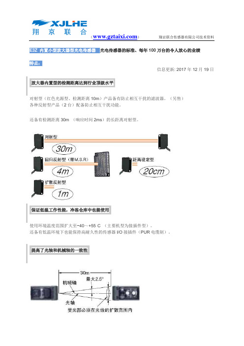
E3Z 内置小型放大器型光电传感器光电传感器的标准、每年100万台的令人放心的业绩特点:信息更新: 2017年12月19日放大器内置型的检测距离达到行业顶级水平对射型(红色光源型、检测距离10m)产品备有防止相互干扰的滤波器。
(另售)各种反射型产品(2台)配备防止相互干扰功能。
还备有检测距离30m (响应时间2ms)的长距离对射型。
保证低温工作性能,冷冻仓库中也能使用使用环境温度范围扩大至−40~+55°C (主要机型为接插件型)。
还备有低温环境下也能保持高耐久性的传感器I/O接插件(PUR电缆制)。
提高了光轴和机械轴的一致性光轴和机械轴的偏差控制在±2.5°以内,只需配合机械轴进行安装,即可与光轴实现高精度对准。
(对射型、回归反射型)即使接线出错,也能保护传感器配备输出反接保护功能。
(输出线路增加反接保护用二极管)完全符合欧洲RoHS指令未使用铅、水银、镉、六价铬、多溴联苯、多溴联苯醚。
包装袋使用可焚烧处理的聚乙烯材料。
种类:信息更新: 2017年7月25日标准型、本体检测方式形状连接方式检测距离型号NPN输出PNP输出对射型(投光器+ 导线引出型(2m)15m(红外光)E3Z-T61 2M *3 *4投光器E3Z-T61-L 2M受光器E3Z-T61-D 2ME3Z-T81 2M *3 *4投光器E3Z-T81-L 2M受光器E3Z-T81-D 2M受光器)接插件型(M8) E3Z-T66投光器E3Z-T66-L受光器E3Z-T66-DE3Z-T86投光器E3Z-T86-L受光器E3Z-T86-D导线引出型(2m)10m(红色光) E3Z-T61A 2M *3投光器E3Z-T61A-L2M受光器E3Z-T61A-D2ME3Z-T81A 2M *3投光器E3Z-T81A-L2M受光器E3Z-T81A-D2M接插件型(M8) E3Z-T66A投光器E3Z-T66A-L受光器E3Z-T66A-DE3Z-T86A投光器E3Z-T86A-L受光器E3Z-T86A-D导线引出型(2m)30m(红外光) E3Z-T62 2M *3投光器E3Z-T62-L 2M受光器E3Z-T62-D 2ME3Z-T82 2M投光器E3Z-T82-L 2M受光器E3Z-T82-D 2M接插件型(M8) E3Z-T67投光器E3Z-T67-L受光器E3Z-T67-DE3Z-T87投光器E3Z-T87-L受光器E3Z-T87-D回归反射型(带M.S.R.功能) *1 导线引出型(2m)4m〔100mm〕(红色光)*2E3Z-R61 2M *3 *4E3Z-R81 2M *3 *4接插件型(M8))E3Z-R66E3Z-R86扩散反射型导线引出型(2m)5~100mm(广视野)(红外光)E3Z-D61 2M *3E3Z-D81 2M *3 *4接插件型(M8) E3Z-D66E3Z-D86导线引出型(2m)1m(红外光)E3Z-D62 2M *3 *4E3Z-D82 2M *3 *4接插件型(M8) E3Z-D67E3Z-D87导线引出型(2m)90±30mm(细光束)(红色光)E3Z-L61 2M *3 *4E3Z-L81 2M *3 *4接插件型(M8) E3Z-L66E3Z-L86距离设定型E3Z-LS 导线引出型(2m)20~40mm(BGS min设定)(红色光)20~200mm(BGS max设定)(红色光)40~受光量受光量阀值(FGS min设定)(红色光)200~受光量E3Z-LS61 2M *3E3Z-LS81 2M *3接插件型(M8) E3Z-LS66E3Z-LS86受光量阀值(FGS max设定)(红色光)导线引出型(2m) 2~20mm(BGS min设定)(红色光)2~80mm(BGS max设定)(红色光)E3Z-LS63 2M E3Z-LS83 2M *4接插件型(M8) E3Z-LS68E3Z-LS88凹槽型对射型E3Z-G 1光轴导线引出型(2m)25mm(红外光)E3Z-G61 2M *3 *4E3Z-G81 2M *3 *4 2光轴E3Z-G62 2M *3E3Z-G82 2M *31光轴接插件型(M8))E3Z-G61-M3E3Z-G81-M3J2光轴E3Z-G62-M3J E3Z-G82-M3J仅限透明玻璃板型反射型导线引出型(2m)30±20mm(红色光)E3Z-L63 2M E3Z-L83 2M 接插件型(M8) E3Z-L68E3Z-L88透明瓶体型回归反射型(无M.S.R功能) *1导线引出型(2m)500mm〔80mm〕(红色光)*2E3Z-B61 2M E3Z-B81 2M *3接插件型(M8))E3Z-B66E3Z-B86导线引出型(2m)2m〔500mm〕(红色光)*2E3Z-B62 2M *3E3Z-B82 2M *3接插件型(M8) E3Z-B67E3Z-B87*1. 不附带反射板。

北京************深圳*************神视光电开关说明书光电传感器样本SUNX PDFSUNX光电开关CX-4订购指南型号(注1)种类形状检测距离NPN输PNP输出投光元件————10m CX-411 CX-411-P 红色LED 透过型长距离15m CX-412 CX-412-P 红外LED 带偏极滤光器3m(注2) CX-491 CX-491-P长距离5m(注2) CX-493 CX-493-P红色LED50~500mm(注2) CX-481 CX-481-P回归反射型透明物体检测用0.1~2m(注2) CX-482 CX-482-P红外LED100mm CX-424 CX-424-P300mm CX-421 CX-421-P ————800mm CX-422 CX-422-P红外LED 扩散反射型窄视角型70~200mm CX-423 CX-423-P 红色LED小光点型CX-441 CX-441-P2~50mmCX-443 CX-443-P15~100mm CX-444 CX-444-P距离设定反射型————20~300mm CX-442 CX-442-P红色LED注:传感器主体未附带安装支架,以便可按照安装方法进行选择。
请选购另行出售的传感器安装支架。
注:1) 记载于透过型产品铭牌的型号中存在符号“E”的机型指的是投光器、存在符号“D”的机型指的是受光器。
(例)CX-411的投光器:CX-411E、CX-411的受光器:CX-411D注:2) 回归反射型的检测距离是指相对于反射镜RF-230的值。
此外,检测距离表示可检测物体的范围。
下表中的检测距离A因检测物体的形状等不同,可能发生变化。
请务必使用实际的检测物体进行动作确认。
CX-491□CX-493□CX-481□CX-482□A0~3m 0~5m 50~500mm 0.1~2mB0.1~3m 0.1~5m 100~500mm 0.8~2m 现货查询 Beijing 86-10-68008909 Shenzhen 86-755-83656710 **************。
E3Z 内置小型放大器型光电传感器光电传感器的标准、每年100万台的令人放心的业绩特点:信息更新: 2017年12月19日放大器内置型的检测距离达到行业顶级水平对射型(红色光源型、检测距离10m)产品备有防止相互干扰的滤波器。
(另售)各种反射型产品(2台)配备防止相互干扰功能。
还备有检测距离30m (响应时间2ms)的长距离对射型。
保证低温工作性能,冷冻仓库中也能使用使用环境温度范围扩大至−40~+55°C (主要机型为接插件型)。
还备有低温环境下也能保持高耐久性的传感器I/O接插件(PUR电缆制)。
提高了光轴和机械轴的一致性光轴和机械轴的偏差控制在±2.5°以内,只需配合机械轴进行安装,即可与光轴实现高精度对准。
(对射型、回归反射型)即使接线出错,也能保护传感器配备输出反接保护功能。
(输出线路增加反接保护用二极管)完全符合欧洲RoHS指令未使用铅、水银、镉、六价铬、多溴联苯、多溴联苯醚。
包装袋使用可焚烧处理的聚乙烯材料。
种类:信息更新: 2017年7月25日标准型、本体检测方式形状连接方式检测距离E3Z-T62-D光电开关E3Z-T62-D光电开关E3Z-T62-D光电开关对射型(投光器导线引出型(2m)15m(红外光)E3Z-T62-D光电开关E3Z-T62-D光电开关+受光器) 接插件型(M8)E3Z-T62-D光电开关E3Z-T62-D光电开关导线引出型(2m) 10m(红色光)E3Z-T62-D光电开关E3Z-T62-D光电开关接插件型(M8)E3Z-T62-D光电开关E3Z-T62-D光电开关导线引出型(2m) 30m(红外光)E3Z-T62-D光电开关E3Z-T62-D光电开关接插件型(M8)E3Z-T62-D光电开关E3Z-T62-D光电开关回归反射型(带M.S.R.功能) *1 导线引出型(2m)4m〔100mm〕(红色光)*2E3Z-T62-D光电开关E3Z-T62-D光电开关接插件型(M8))E3Z-T62-D光电开关E3Z-T62-D光电开关扩散反射型导线引出型(2m)5~100mm(广视野)(红外光)E3Z-T62-D光电开关E3Z-T62-D光电开关接插件型(M8)E3Z-T62-D光电开关E3Z-T62-D光电开关导线引出型(2m) 1m(红外光)E3Z-T62-D光电开关E3Z-T62-D光电开关接插件型(M8)E3Z-T62-D光电开关E3Z-T62-D光电开关导线引出型(2m)90±30mm(细光束)(红色光)E3Z-T62-D光电开关E3Z-T62-D光电开关接插件型(M8)E3Z-T62-D光电开关E3Z-T62-D光电开关距离设定型E3Z-LS 导线引出型(2m)20~40mm(BGS min设定)(红色光)20~200mm(BGS max设定)(红色光)40~受光量受光量阀值(FGS min设定)(红色光)200~受光量受光量阀值(FGS max设定)(红色光)E3Z-T62-D光电开关E3Z-T62-D光电开关接插件型(M8)E3Z-T62-D光电开关E3Z-T62-D光电开关导线引出型(2m)2~20mm(BGS min设定)E3Z-T62-D光电开关E3Z-T62-D光电开关接插件型(M8) (红色光)2~80mm(BGS max设定)(红色光)E3Z-T62-D光电开关E3Z-T62-D光电开关凹槽型对射型E3Z-G 1光轴导线引出型(2m)E3Z-T62-D光电开关E3Z-T62-D光电开关E3Z-T62-D光电开关E3Z-T62-D光电开关E3Z-T62-D光电开关E3Z-G81 2M *3 *4 2光轴E3Z-T62-D光电开关E3Z-G82 2M *31光轴接插件型(M8))E3Z-T62-D光电开关E3Z-G81-M3J2光轴E3Z-T62-D光电开关E3Z-G82-M3J仅限透明玻璃板型反射型导线引出型(2m) 30±20mm(红色光)E3Z-T62-D光电开关E3Z-T62-D光电开关接插件型(M8)E3Z-T62-D光电开关E3Z-T62-D光电开关透明瓶体型回归反射型(无M.S.R功能) *1 导线引出型(2m)500mm〔80mm〕(红色光)*2E3Z-T62-D光电开关E3Z-T62-D光电开关接插件型(M8))E3Z-T62-D光电开关E3Z-T62-D光电开关导线引出型(2m)2m〔500mm〕(红色光)*2E3Z-T62-D光电开关E3Z-T62-D光电开关接插件型(M8)E3Z-T62-D光电开关E3Z-T62-D光电开关*1. 不附带反射板。
常开触点术语英文
常开触点是电子元件中常用的一种开关类型,常常用于控制电路中的电流。
以下是一些常开触点相关的术语及其英文表达:
1. 常开触点:Normally Open Contact (NOC)
2. 常开继电器:Normally Open Relay (NOR)
3. 常开开关:Normally Open Switch (NOS)
4. 常开型限位开关:Normally Open Limit Switch (NOLS)
5. 常开型感应开关:Normally Open Inductive Sensor (NOIS)
6. 常开型光电开关:Normally Open Photoelectric Sensor (NOPES)
7. 常开型接近开关:Normally Open Proximity Switch (NOPXS)
8. 常开型按钮开关:Normally Open Push Button Switch (NOPBS)
9. 常开型磁性开关:Normally Open Magnetic Switch (NOMS)
10. 常开型温控开关:Normally Open Temperature Control Switch (NOTCS)
以上仅为常见常开触点术语的英文表达,实际应用中还有其他类别和变种,需要结合具体情况进行选择。
- 1 -。
责声明:本文档不代表或不用于确定用于特定用户应用产品的适用性或可靠性产品参数表说明书XUB5ANANM12光电开关,漫射式主要信息产品系列OsiSense XU 系列号一般用途,单一模式电子传感器类型光电传感器传感器名称XUB 传感器外形M18圆柱型检测系统漫射材料塑料视线类型轴向输出信号类型离散输入类型直流接线技术3-线固态输出类型NPN 固态输出功能 1 NO电气连接 1 针型接头 M12, 4 针应用领域-发射红外线 漫射额定感应距离0.6 m 漫射补充信息机柜材料PBT 透镜材料PMMA 最大传感距离0.8 m 漫射输出类型固态输出附件无导线绝缘材料PvRLED状态LED (黄) 适用 输出状态额定电源电压 [Us]12...24 V 直流 和 逆相保护电源电压范围10...36 V 直流开关能力以 mA <= 100 mA (过载和短路保护)开关频率<= 500 Hz 压降1.5 V (闭合状态)电流消耗35 mA (无负荷)启动延迟< 15 ms响应延迟< 1 ms复位延迟< 1 ms设置灵敏度调节直径18 mm长度78 mm产品重量0.045 kg环境产品认证CECSAUL环境温度-25...55 °C贮存环境温度-40...70 °C抗振动7 gn, 振幅 = +/- 1.5 mm (f = 10...55 Hz) 符合 IEC 60068-2-6抗冲击30 gn (持续时间 = 11 ms) 符合 IEC 60068-2-27IP 保护等级IP65 双重绝缘 符合 IEC 60529IP67 双重绝缘 符合 IEC 60529IP69K 双重绝缘 符合 DIN 40050可持续性RoHS法规(日期代码:YYWW)符合 - 自从 2008年第47周 - Schneider Electric declaration of conformitySchneider Electric declaration of conformityREACh法规有毒有害物质含量均在REACH规定的范围之内有毒有害物质含量均在REACH规定的范围之内合同保修阶段18 个月尺寸图尺寸接线接线图M12 连接器1:(+)3:(-)4:OUT/输出NPN 输出性能曲线检测曲线1:白色 90% 2:灰色 18%检测目标 10 x 10 厘米。
Table of ContentsTable of ContentsPreface (iii)User Manual Guide (iv)User Manual Symbols (v)Safety Considerations (vi)Cautions during Use (vii)Table of Contents (ix)1Product Overview (13)1.1Features (13)1.2Components and Accessories (13)1.2.1Components (13)1.2.2Sold separately (14)1.3Ordering information (15)1.4Unit description (16)1.4.1CXS Series (16)1.4.2CXM Series (16)2Specifications (19)3Dimensions (23)3.1CXS Series (23)3.2CXM Series (23)3.3Panel cut-out dimension (24)3.3.1CXS Series (24)3.3.2CXM Series (24)3.4Bracket (25)3.4.1CXS Series (25)3.4.2CXM Series (25)4Connection Method (27)4.1Connection (27)4.1.1CXS Series (27)4.1.2CXM Series (30)4.2Input and Output connection (32)4.2.1Input connection (32)4.2.2Output connection (33)5Counter mode (35)5.1Basic Operations (35)5.1.1Operations and functions (35)5.1.2Function setting mode (36)5.1.3Changing SV mode (37)5.1.4Checking SV of TOTAL counter (38)5.1.5Function setting check modeTable of Contents(only for free voltage input model (CX6□-□□F)) (38)5.1.6Switching display of the setting value display component (38)5.1.7Display HOLD output mode for counter (38)5.1.8RESET (38)5.2Parameter setting (39)5.2.1Counter/Timer (41)5.2.2Input mode (41)5.2.3Output mode (41)5.2.4Max. counting speed (41)5.2.5OUT2 output time (41)5.2.6OUT1 output time (42)5.2.7Decimal point (43)5.2.8Min. reset time (43)5.2.9Input logic (43)5.2.10Prescale (44)5.2.11Prescale decimal point (45)5.2.12Prescale value (45)5.2.13TOTAL Counter (45)5.2.14Start point value (46)5.2.15Memory protection (47)5.2.16Key lock (47)5.3Input mode (48)5.4Output mode (52)5.5Output operation for other conditions (55)5.5.1Start point value is larger than setting value(UP, UP-1, UP-2, UP-3, UD-A, UD-B, UD-C mode) (55)5.5.2When SET1 is larger or equal than SET2 at down mode (56)6Timer mode (57)6.1Basic Operations (57)6.1.1Operations and functions (57)6.1.2Function setting mode (58)6.1.3Changing SV mode (59)6.1.4Changing SV operation (59)6.1.5Switching display of the setting value display component (59)6.1.6RESET (60)6.1.7Display type of the setting value display component by output mode (60)6.1.8Timer display operation (60)6.1.9Zero blanking display (60)6.2Parameter setting (61)6.2.1Counter/Timer (63)6.2.2UP/DOWN mode (63)6.2.3Output mode (63)6.2.4Time range (64)6.2.5OUT2 (OUT) output time (64)6.2.6OUT1 output time (65)6.2.7Input logic (65)6.2.8Input signal time (65)6.2.9Memory protection (66)6.2.10Key lock (66)Table of Contents6.3Output operation mode (67)6.4Timer ‘0’ time setting (77)6.4.1Timer output mode for ‘0’ time setting (77)6.4.2Operations by output mode (‘0’ time setting) (77)7Factory Default (85)7.1Common (85)7.2Counter (85)7.3Timer (86)11.11.21.2.1ProduFeatu[Common▪Impro▪Input: voltaFree▪Settin▪Moun[Counter]▪Settin▪Vario▪Start▪TOTA: Disp[Timer]▪Vario▪Wide▪'0' timCompCompoMake sureIf a compouct Ovresn]oved visibilitymethodage input (PNe voltage inpng range of onting space sng range of pous input/outppoint (countAL counter dplays the preous output moe time settingme setting funponentsonentse all of the aonent is missverviewy with LCD dNP)/no-voltaput modelone-shot outpsaving with cprescale valuput mode (ining value resisplay modeesent value aode (15 typerange: 0.00nctionand Acbove composing or damawdisplayage input (NPput time: 0.0compact desiue: 0.00001 tput: 11 typesset) settingand the integes)1 sec to 999ccessoronents are incaged, pleasePN) selectab1 sec to 99.9ign (back lento 99999.9s, output: 11rated value s999.9 hourriescluded with ye contact Autole model (by99 sec by 0.0ngth: 64.5mmtypes)simultaneousyour productonics or your1 Produy parameter s01 sec unitm)sly.t package ber distributor.uct Overviewsetting),efore use.w1 Product Overview1.2.2Sold separately(1)Terminal cover1) RSA-COVER (48×48mm)2) RMA-COVER (72×72mm)1 Product Overview 1.3Ordering informationCX 6 S - 1P 4 F①②③④⑤⑥Item Description①Item CX LCD Display Counter/Timer②Display digit 6 999999 (6-digit)③Size S DIN W48 × H48mm M DIN W72 × H72mm④Output 1P 1-stage setting 2P 2-stage setting⑤Power supply 2 24VAC 50/60Hz, 24-48VDC 4 100-240VAC 50/60Hz⑥Signal input method No mark Voltage input (PNP)/no-voltage input (NPN) selectable typeF Free voltage input1 Product Overview1.4Unit description1.4.1CXS Series1.4.2CXM Series(1)Counting value display component (red)RUN mode: Displays counting value for counter operation or time progress value for timeroperation.Function setting mode: Displays parameter.(2)Setting value display component (green)RUN mode: Displays setting value.Function setting mode: Displays setting content.1 Product Overview(3)Time unit indicator (h:m:s): Turns ON for time unit for timer.(4)Key lock indicator ():Turns ON for key lock setting.(5)Reset input indicator (RST): Turns ON for reset key input or reset signal input.(6)INH indicator (INH): For the voltage input (PNP)/no-voltage input (NPN) selectable model (CX6□-□□),it turns ON for INHIBIT signal input. (In case of CX6S Series and timer mode, it turns ON for INB/INH signal input.)For free voltage input model (CX6□-□□F), it turns ON for INB/INH signal input for timer.(7)Output indicator (OUT1, OUT2): Turns ON for the dedicated control output ON.(8)SV checking and changing indicator (SET, SET1, SET2) (green): Turns ON when checking and changing SV.(9)COUNTER indicator (COUNTER): Turns ON for counter operation.(10)TOTAL indicator※1(TOTAL): In case of TOTAL counter display mode, it turns ON with the COUNTER indicator.(11)TIMER indicator(TIMER): Flashes (progressing time) or Turns ON (stopping time) for timer operation.(12)keyRUN mode, Function setting mode: Press the key to reset the counting value andTOTAL counter display mode※1: Press the key to reset the counting value ofTOTAL counter.(13)key: Hold the key over 3 sec to enter function setting mode.Press the key to select SV2 (SET2)/ SV1 (SET1)/TOTAL counter※1 display forcounter operation.key to save the SV: Hold theChanging SV mode: Press the(14)key1) keyRUN mode: Press the Press the key to change SV and move SVkey to change digits.2) keyChanging SV mode: Increases SV.Function setting mode: Changes the settings.1 Product Overview※1: This is for the voltage input (PNP)/no-voltage input (NPN) selectable model (CX6□-□□).2 Specifications2SpecificationsSeries CXS CXMModel CX6S-1P□□CX6S-2P□□CX6M-1P□□CX6M-2P□□Display digits 6-digitDisplay method 7-segment (1st, 2nd digits of counting value display: white,setting value display: green) LCD method,11-segment (the other digits of counting value display: white) LCD method, Operation display part: yellow LCD methodCharacter size (W×H) Counting value 4.1×10.1mm 6.2×15.2mm Setting value 3.3×8.1mm 5×12.3mmPower supply AC voltage 100-240VACЖ 50/60HzAC/DC voltage 24VACЖ 50/60Hz, 24-48VDCЗPermissible voltage range 90 to 110% of rated voltagePower consump tion ACvoltageCX6□-□□Max. 6.4VA Max. 6.7VA Max. 7.1VA Max. 7.5VACX6□-□□F Max. 4.2VA Max. 4.9VA Max. 4.7VA Max. 5.4VAAC/DCvoltageCX6□-□□AC: max. 5.5VADC: max. 3.5WAC: max. 5.6VADC: max. 3.6WAC: max. 6.2VADC: max. 4WAC: max. 6.3VADC: max. 4.1WCX6□-□□FAC: max. 3.6VADC: max. 2.5WAC: max. 4.0VADC: max. 2.8WAC: max. 3.9VADC: max. 2.9WAC: max. 4.5VADC: max. 3.3WCounter Max.INA/INBcountingspeedCX6□-□□Selectable among 1cps/30cps/300cps/1kcps/5kcpsCX6□-□□F 20cpsCounting range -99999 to 999999Scale Decimal point up to fifth digitMin.signalwidthCX6□-□□RESET, TOTAL RESET signal: selectable among 1ms/20msCX6□-□□F RESET signal: 25msTimer Time range 999.999s, 9999.99s, 99999.9s, 999999s, 99m59.99s, 999m59.9s, 9999m59s, 99999.9m, 999999m, 99h59m59s, 9999h59m, 99999.9hOperation mode Up, DownMin.signalwidthCX6□-□□INA, INHIBIT, RESET, TOTAL RESET signal: selectable among 1ms/20msCX6□-□□F INA, INH, RESET signal: 25msRepeat error [CX6□-□□] – In case of power ON start: max. ±0.01% ±0.05sIn case of signal ON start: max. ±0.01% ±0.03s[CX6□-□□F] - In case of power ON start: max. ±0.01% ±0.08sIn case of signal ON start: max. ±0.01% ±0.06sSET errorVoltage errorTemperature error2 Specifications2 Specifications※1: This is for the voltage input (PNP)/no-voltage input (NPN) selectable model (CX6□-□□). ※2: The weight includes packaging. The weight in parenthesis for unit only.※Environment resistance is rated at no freezing or condensation.3 Dimensions3Dimensions(unit: mm) 3.1CXS Series3.2CXM Series3 Dimensions3.3Panel cut-out dimension(unit: mm) 3.3.1CXS Series3.3.2CXM Series3 Dimensions3.4Bracket(unit: mm) 3.4.1CXS Series3.4.2CXM Series4 Connection Method 4Connection Method4.1Connection4.1.1CXS Series(1)Voltage input(PNP)/no-voltage input(NPN) selectable model1) CX6S-1P□※1: AC voltage type: 100-240VAC 50/60HzAC/DC voltage type: 24VAC 50/60Hz, 24-48VDC4 Connection Method2) CX6S-2P23) CX6S-2P4※2: AC/DC voltage type: 24VAC 50/60Hz, 24-48VDC※3: AC voltage type: 100-240VAC 50/60Hz4 Connection Method(2)Free voltage input model1) CX6S-1P□F2) CX6S-2P2F3) CX6M-2P4F※1: AC voltage type: 100-240VAC 50/60HzAC/DC voltage type: 24VAC 50/60Hz, 24-48VDC4 Connection Method4.1.2CXM Series(1)Voltage input(PNP)/no-voltage input(NPN) selectable model1) CX6M-1P□2) CX6M-2P□※1: AC voltage type: 100-240VAC 50/60HzAC/DC voltage type: 24VAC 50/60Hz, 24-48VDC4 Connection Method(2)Free voltage input model1) CX6M-1P□F2) CX6M-2P□F※1: AC voltage type: 100-240VAC 50/60HzAC/DC voltage type: 24VAC 50/60Hz, 24-48VDC4 Connection Method4.2Input and Output connection 4.2.1Input connection(1)Voltage input (PNP)1)2) Contact input(2)No-voltage input (NPN)1)2) Contact input※1: CP1, CP2(INHIBIT), SET input part※2: Set counting speed as 1 or 30cps.4 Connection Method4.2.2Output connection(1)Contact outputSelect the load which capacity is not over contact capacity.(2)Solid-state output▪For solid state output, select load power and load not to be over (max. 30VDC, 100mA), switching capacity.▪Do not supply reverse polarity voltage.※1: For using inductive load (relay, etc), connect surge absorber (diode, varistor, etc) at the both ends of load.5 Counter mode 5Counter mode5.1Basic Operations5.1.1Operations and functions5 Counter mode5.1.2Function setting mode▪Hold the key over 3 sec in RUN mode and it enters function setting mode.▪Hold the key over 3 sec in function setting mode and it returns to RUN mode.※1: In case of free voltage input model (CX6□-□□F) , these parameters do not appear due to fixed setting.※2: This parameter is for the voltage input(PNP)/no-voltage input(NPN) selectable model(CX6□-□□).When returning RUN mode, PV is reset.※In case of 1-stage setting model(CX6□-1P□□), OUT1output time does not appear.OUT2 output time is displayed as OUtT.5 Counter mode※When input mode is DN, DN-1, DN-2, or DN-3, start point [START] parameter does notappear.※When total count function is ON, start point [START] parameter does not appear.(This is for the voltage input(PNP)/no-voltage input(NPN) selectable model (CX6□-□□).)※When output mode is F, N, S, T, or D, OUT2 output time dose not appear. (fixed as HOLD)※When output mode is S, T, or D, OUT1 output time does not appear.※Even though entering RUN mode and function setting mode, it operates counter counting andoutput control.※When changing operation setting value at function setting mode, all output turn OFF and it isreset when it returns to RUN mode.5.1.3Changing SV mode▪Press the key to enter changing SV mode in RUN mode.▪When input signal is ON during changing SV, it operates counting and output control.It is available to set SV as '0' and the dedicated output for SV '0' occurs.▪There are output mode which cannot set SV as '0'.(the setting value display component flashes three times when SV is set as '0') ▪When entering changing SV mode, the counting value display component displays the current value and the setting value display component displays SV.▪When setting 1-stage SV and 2-stage SV, each “SET1”, “SET2” indicator turns ON.▪In case of 1-stage setting model (CX6□-1P□□), SET2 is displayed as SET and SET1 is not displayed.▪After setting SV at each parameter, press the key to save SV and it moves nextparameter setting or returns to RUN mode.5 Counter mode5.1.4Checking SV of TOTAL counter▪Press thekey in RUN mode and it operates SET2 → SET1 → TOTAL Counter in order.▪At TOTAL counter operation, the counting value display component displays the current value and the setting value display component displays TOTAL counter counting value.▪When TOTAL counter counting value is over 999999, it counts from 0 again.5.1.5Function setting check mode(only for free voltage input model (CX6□-□□F))▪Hold the key over 1 sec to enter function setting check mode in RUN mode.▪When checking the saved parameters, press the key to check next item.▪Hold the key over 1 sec at function setting check mode and it returns to RUN mode.▪At function setting check mode, the counting value display component displays the parameters and the setting value display component displays the SV of the parameters. 5.1.6Switching display of the setting value display componentIn case of 2-stage setting model(CX6□-2P□□), whenever pressing the key, each SET2,SET1, TOTAL COUNTER※1 value displays consecutively.※1: This is for the voltage input(PNP)/no-voltage input(NPN) selectable model (CX6□-□□). 5.1.7Display HOLD output mode for counter▪It displays the over value of prescale value.▪When SV is n multiplied by prescale value and the display value after HOLD output mode and SV are different, the prescale value is not the 1/n time of SV.5.1.8RESET▪In RUN mode, function setting mode, press the key to reset the current value andthe output turns OFF.▪At TOTAL counter display mode※1, press the key to reset TOTAL counter countingvalue and the current counting value.※1: This is for the voltage input(PNP)/no-voltage input(NPN) selectable model (CX6□-□□).TOTAL counter display mode is only when counter operation.5 Counter mode5.2Parameter settingkey: moves parameters,key: changes parameter setting value)5 Counter mode※1: This is for the voltage input(PNP)/no-voltage input(NPN) selectable model (CX6□-□□).※2: For free voltage input model(CX6□-□□F), these parameters do not appear due to fixedsetting.※3: For 1-stage setting model (CX6□-1P□□), OUT1 output time does not appear.The OUT2output time is displayed as OUtT.※4: Decimal point and prescale decimal point•Decimal point: Set the decimal point for display value regardless of prescale value.•Prescale decimal point: Set the decimal point for prescale value of counting value regardless of display value.5 Counter mode5.2.1Counter/TimerSelect operation type as counter or timer.※Right after the selecting counter/timer, the below parameters are changes as the dedicatedoperation.5.2.2Input modeSelect one counter input mode; up input [UP, UP-1, UP-2, UP-3], down input [DN, DN-1, DN-2,DN-3], command input [UD-A], individual input [UD-B]※1, phase-difference input [UD-C]※1 .※1: This is for the voltage input(PNP)/no-voltage input(NPN) selectable model (CX6□-□□).5.2.3Output modeSelect one counter output mode; F, N, C, R, K, P, Q, A, S, T, D mode.※In case of input mode UD-A, UD-B※1, UD-C※1, output mode S, T, D setting is available.※When max. counting speed is set as 5kpcs, and output mode is D, max. counting speed ischanged as 30cps automatically.※1: This is for the voltage input(PNP)/no-voltage input(NPN) selectable model (CX6□-□□).5.2.4Max. counting speedSelect one max. counting speed of INA, INB; 1cps, 30cps, 300cps, 1kcps, 5kcps.※In case of D output mode, select one; 1cps, 30cps, 300cps, 1kcps.5.2.5OUT2 output timeSet one-shot output time of OUT2 output. (unit: sec)※Setting range: 00.01 to 99.99s▪key: Moves the setting digits of output time value.▪key: Changes the flashing digit value.※In case of 1-stage setting model(CX6□-1P□□), OUT1output time does not appear.OUT2output time is displayed as OUtT.※In case of F, N, S, T, D output mode, OUT2 does not appear. (fixed as HOLD)5 Counter mode(1)When changing output time setting as 500ms,1) Press the key to move the flashing digit at the setting value display component.2) Press the keys to set as 5 of the 2nd digit.3) Press the key to save SV and enter next parameter setting.5.2.6OUT1 output timeSet output operation (HOLD) and one-shot output time of OUT1 output. (unit: sec)※Setting range: 00.01 to 99.99s, HOLD▪key: Moves the setting digit of output time.▪key: Changes the flashing digit value.※In case of 1-stage setting model (CX6□-1P□□), OUT1 does not appear.(1)When changing output time setting as HOLD,1) When number of tens digit flashes, press the key once and HOLD is displayed.2) Press the key to save SV and moves to next parameter.(2)When changing output time setting from HOLD to 120ms,1) When HOLD is displayed, press the key once and moves the 1st digit of the settingvalue display component.2) Press the key to set as 2 of 1st digit.3) Press the key to move digit to the 2nd digit.4) Press the key to set as 1 of 2nd digit.5) Press the key to save SV and moves to next parameter.(3)Setting parameter order5.2.7Decimal pointSet decimal point of counting value and SV in RUN mode.5.2.8Min. reset timeSelect min. signal width of the external RESET signal input. (unit: ms)5.2.9Input logicSelect external signal input logic; NPN or PNP input.5.2.10 PrescaleThis function is to set and display calculated unit for actual length, liquid, position, etc. It is called “prescale value” for measured length, liquid, or position, etc per 1 pulse. For example, when moving L, the desired length to be measured, and P , the number of pulses per 1 revolution of a rotary encoder, occurs, prescale value is L/P .Positioning control by counter and encoder[Diameter (D) of pulley connected with encoder= 22mm, the number of pulses by 1 rotation of encoder=1,000]Prescale value =π × Diameter (D ) of pulley (D )The number of pulses by 1 rotaiton of encoder=3.1416×221000= 0.069mm/pulseSet decimal point [DP ] as [-----.-] mode, prescale decimal point [SClDP ] as [---.---] and prescale value[SCL ] parameter as [)069] at function setting mode. It is available to control conveyer position by 0.1mm unit.5.2.11Prescale decimal pointSet decimal point of prescale value.※Decimal point of prescale should not set smaller than decimal point [DP].5.2.12Prescale valueSet the prescale value of counter counting value.▪key: Moves the setting digit of prescale value.▪key: Changes the flashing digit value.※When setting prescale value as 78.1121,①Prescale decimal point positionSet decimal point of prescale referring to [5.2.11 prescale decimal point].②5.2.13TOTAL CounterSet TOTAL counter operation ON/OFF.※In case of TOTAL counter OFF and at RUN mode, press the key and it changes to SVdisplay mode.5.2.14Start point valueIn case of counter operation, set the start value for counting at Start point [START].▪It is not available for DN, DN-1, DN-2, DN-3 input mode.▪It is not available when TOTAL COUNTER※1 is ON.▪When pressing the RESET key, PV is reset as the start point value.▪In case of C, R, P, Q output mode, it counts up and PV starts from the start point value.▪In case of counter operation and UP, UP-1, UP-2, UP-3, UD-A, UD-B※1, UD-C※1 input mode, start point setting is available.▪When changing the start point value at function setting mode and returning to RUN mode, PV is changed as the start point value.When changing the start point value at function setting mode, PV is reset.▪Setting range: 0.00000 to 999999▪Start point setting method is same as SV setting method.▪Setting range of start point value is linked with decimal point [DP].※1: This is for the voltage input(PNP)/no-voltage input(NPN) selectable model (CX6□-□□).※Start point for F output mode※Start point for C output mode5.2.15Memory protectionSet counting value memory protection when the unit power OFF to ON.※CLR: Resets the counting value when power OFF.REC: Maintains the counting value when power OFF. (memory protection) 5.2.16Key lockSet key lock function depending on counter/timer operation.※lOFF: Unlock keys.LOc1: LocksLOc2: LocksLOc3: Locks keys.5.3Input mode※1: This is for the voltage input(PNP)/no-voltage input(NPN) selectable model (CX6□-□□).these width, it may cause counting error (±1).※The meaning of “H”, “L”※Min. signal width by counting speed (1cps=1Hz)▪CX6□-□□Counting speed Min. signal width1cps 500ms30cps 16.7ms300cps 1.67ms1kcps 0.5ms5kcps 0.1ms▪CX6□-□□FCounting speed Min. signal width20cps 25ms5.4Output mode5 Counter mode5 Counter mode※OUT1 is available to set as ‘0’ regardless of output mode. The output for '0' setting executes.※In case of C, R, P, Q output mode for OUT2, setting ‘0’ is not available.5 Counter mode 5.5Output operation for other conditions5.5.1Start point value is larger than setting value(UP, UP-1, UP-2, UP-3, UD-A, UD-B, UD-C mode)(1)When setting SET > Start point > SET1▪UP, UP-1, UP-2, UP-3 mode: Output of OUT1 does not execute. When PV is same as SET2, output of OUT2 turnsON.▪UD-A, UD-B※1, UD-C※1 mode: When PV counts down and is same as SET1, output of OUT1 turns ON.※Output mode: FInput mode: UP, UP-1, UP-2, UP-3※Output mode: FInput mode: UD-A, UD-B※1, UD-C※1(2)When setting SET2 > Start point = SET1In case of UP, UP-1, UP-2, UP-3, UD-A, UD-B※1, UD-C※1 mode, output of OUT1 turns ONwhen RESET ON to OFF.※1: This is for the voltage input(PNP)/no-voltage input(NPN) selectable model (CX6□-□□).5 Counter mode5.5.2When SET1 is larger or equal than SET2 at down mode(1)When SET1 > SET2▪Output of OUT1 does not execute.※Output mode: F(2)When SET1 = SET2▪Output of OUT1 turns ON for RESET OFF.※Output mode: F6 Timer mode 6Timer mode6.1Basic Operations6.1.1Operations and functions6 Timer mode6.1.2Function setting mode▪Hold the key over 3 sec in RUN mode and it enters function setting mode.▪Hold the key over 3 sec in function setting mode and it returns to RUN mode.※1: In case of free voltage input model (CX6□-□□F) , these parameters do not appear due to fixed setting.※2: Memory protection menu is available when output mode is ONtD.RUN mode, PV is reset.※When output mode is FLk1, FLk2, INTG, or output mode is OND, ONd1, ONd2, ONd3for 1-stage setting model (CX6□-1P□□), OUT1 output time does not appear. OUT2 outputtime is displayed as OUtT.※When output mode is FLK, FLk1, FLk2, INT, INt1, OFD, NFD, NFd1, INTG, TOTAL, ONtD,OUT2 output time does not appear.※Even though entering RUN mode and function setting mode, it operates timer and outputcontrol.※When changing operation setting value at function setting mode, all output turn OFF and it isreset when it returns to RUN mode.6 Timer mode 6.1.3Changing SV mode6.1.4Changing SV operation▪Even though entering changing SV mode, the counting value display component displays PV.▪Even though changing SV, it operates time progress and output control.▪Press the key to enter changing SV mode in RUN mode.▪When setting 1-stage SV and 2-stage SV, each “SET1”, “SET2” indicator turns ON.▪In case of 1-stage setting model (CX6□-1P□□), SET2 is displayed as SET and SET1 is not displayed.▪After setting SV at each parameter, press the key to save SV and it moves nextparameter setting or returns to RUN mode.6.1.5Switching display of the setting value display componentSelect the display value at the setting value display component. Depends on output mode, thereare manual display switching and auto display switching.(1)Manual display switching1) In case of 2-stage setting model (CX6□-2P□□) and OND, ONd1, ONd2, ONd3 outputmode, it is available.2) In run mode, whenever pressing the key, the setting value display componentdisplays SET1, SET2 SV in turn. In case of 1-stage setting model (CX6□-1P□□), it isnot available.6 Timer mode(2)Auto display switching1) When output mode is FLK, NFD, NFd1for 1-stage or 2-stage setting model (CX6□-1/2P□□) and INt2 mode for 2-stage setting model (CX6□-2P□□), the setting valuedisplay component automatically displays the set times depends on the operationstatus.6.1.6RESETIn RUN mode, function setting mode, press the key to reset the current value and theoutput is also reset.6.1.7Display type of the setting value display component by outputmode▪In case of 2-stage setting model (CX6□-2P□□) and OND, ONd1, ONd2, ONd3, INt2 output mode, there are SET1 and SET2 setting. It displays the each SV and the SET1,SET2 indicator turns ON when displaying or setting the each SV.▪In case of 1-stage setting model (CX6□-1P□□) , SET is available and there is one setting value.▪In case of 1-stage setting model (CX6□-1P□□), INt2 output mode is not available.▪FLK output mode has tOFF, tON setting values. In case of 2-stage setting model(CX6□-2P□□) and 1-stage setting model (CX6□-1P□□), each SET2, SET display isavailable. (tOFF, tON setting value is for OUT2 output. It displays SET2 or SET.) ▪The other output modes display SET2 or SET and have one setting value.(only for 1-stage setting model (CX6□-1P□□))6.1.8Timer display operation▪During timer progress, TIMER indicator flashes.▪When timer stops or holds, TIMER indicator turns ON.6.1.9Zero blanking displayPV is displayed with zero blanking for the highest unit.When time range is 99m59.99s and PV is 00m04.05s, zero blanking is applied to minute whichis the highest unit. At the below digits of decimal point, it is not applied. It displays as “0:04.05”.。