毕业设计外文资料翻译
系部:机械工程系
专业:材料成型及控制工程
姓名:
学号:
外文出处:
https://www.doczj.com/doc/9c3261068.html,
附件: 1.外文资料翻译2.外文原文
2012年03月05日
一个描述电铸镍壳在注塑模具的应用的技术研究
——Universidad de Las Palmas de Gran Canaria,Departamento de Ingenieria Mecanica,Spain
摘要:
在过去几年中快速成型技术及快速模具已被广泛开发利用.在本文中,使用电芯作为核心程序对塑料注射模具分析.通过差分系统快速成型制造外壳模型.主要目的是分析电铸镍壳力学特征、研究相关金相组织,硬度,内部压力等不同方面,由这些特征参数以生产电铸设备的外壳.最后一个核心是检验注塑模具.
关键词:电镀;电铸;微观结构;镍
1.引言
现代工业遇到很大的挑战,其中最重要的是怎么样提供更好的产品给消费者,更多种类和更新换代问题.因此,现代工业必定产生更多的竞争性.毫无疑问,结合时间变量和质量变量并不容易,因为他们经常彼此互为条件;先进的生产系统将允许该组合以更加有效可行的方式进行,例如,如果是观测注塑系统的转变、我们得出的结论是,事实上一个新产品在市场上具有较好的质量它需要越来越少的时间快速模具制造技术是在这一领域,中可以改善设计和制造注入部分的技术进步.快速模具制造技术基本上是一个中小型系列的收集程序,在很短的时间内在可接受的精度水平基础上让我们获得模具的塑料部件。其应用不仅在更加广阔而且生产也不断增多。
本文包括了很广泛的研究路线,在这些研究路线中我们可以尝试去学习,定义,分析,测试,提出在工业水平方面的可行性,从核心的注塑模具制造获取电铸镍壳,同时作为一个初始模型的原型在一个FDM设备上的快速成型。
不得不说的是,先进的电铸技术应用在无数的行业,但这一研究工作调查到什么程度,并根据这些参数,使用这种技术生产快速模具在技术上是可行的.都产生一个准确的,系统化使用的方法以及建议的工作方法.
2制造过程的注塑模具
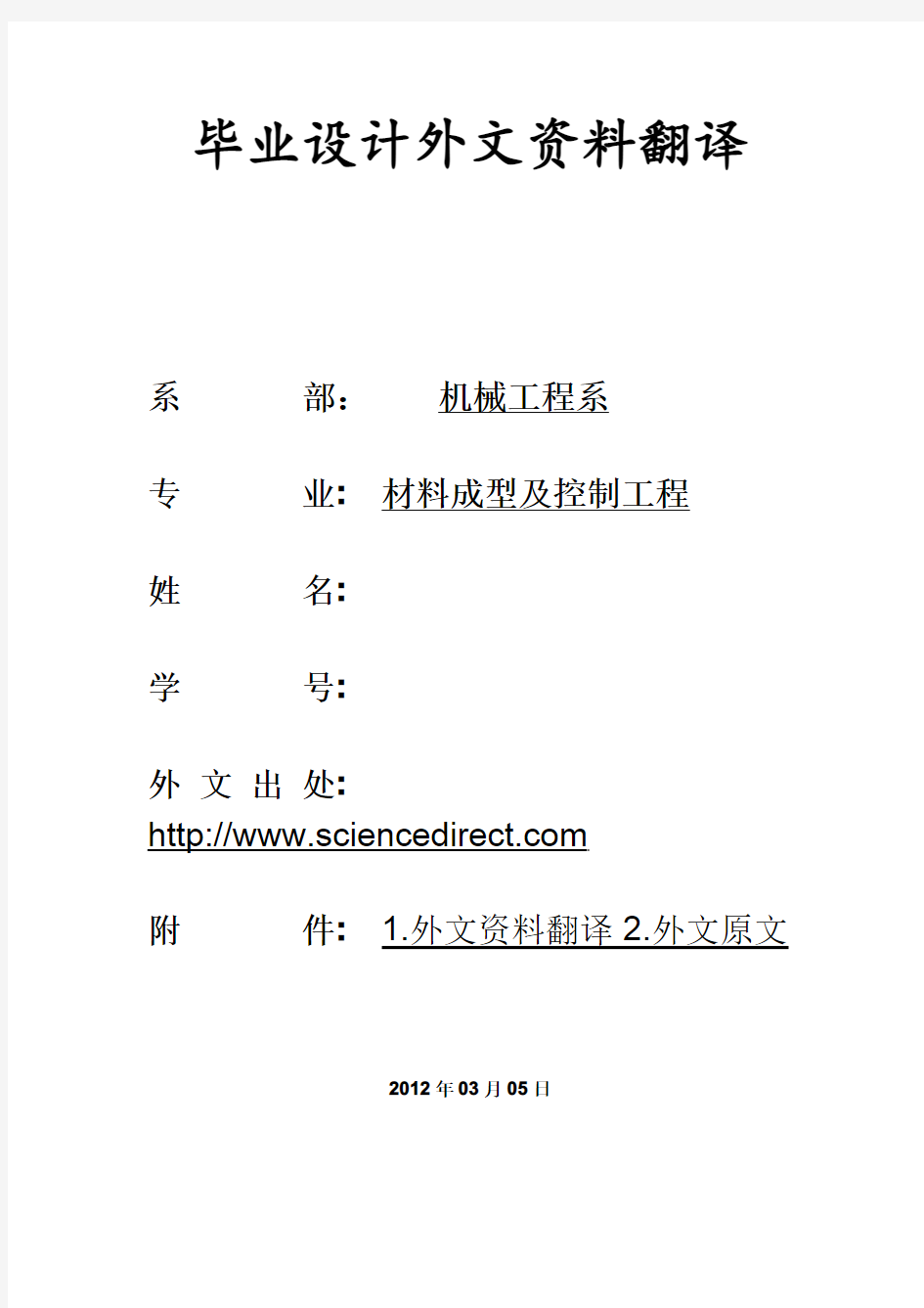
薄镍外壳的核心是电铸,获得一个充满epoxic金属树脂的一体化的核心板块模具(图1)允许直接制造注射型多用标本,因为它们确定了新英格兰大学英文国际表卓华组织3167标准。这样做的目的是确定力学性能的材料收集代表行业。
该阶段取得的核心[4],根据这一方法研究了这项工作,有如下:
a,用CAD系统设计的理想对象
b模型制造的快速成型设备(频分多路系统).所用材料将是一个ABS塑料
c一个制造的电铸镍壳,已事先涂有导电涂料(必须有导电).
d无外壳模型
e核心的生产是背面外壳环氧树脂的抗高温与具有制冷的铜管管道.
有两个腔的注塑模具、其中一个是电核心和其他直接加工的移动版.因此,在同一工艺条件下,同时注入两个标准技术制造,获得相同的工作。
3获得电壳:设备
电镀是电解质时电流的化学变化,电解所形成的直流电有两个电极,阳极和阴极。当电流流经电路,在离子溶液中转化为原子。
电镀液用于这项工作是由氨基磺酸镍400毫升/升,氯化镍(10克/升)、硼酸(50克/升),allbrite SLA(30毫升/升),allbrite703(2毫升/升).选择这种组合主要原因是我们考虑注塑模具程序是玻璃纤维.氨基磺酸镍让我们获得可以接受的内部压力(测试不同工艺条件结果,而不是最佳工艺条件约2兆帕最高为50兆帕).不过,这种内部压力是由touenesulfonamode 衍生物和甲醛水溶液使用的ALLbrite添加剂的结果。
这种添加剂也增加了壳的阻力.Allbrite703是一种可生物降解水溶液表使用剂氯化镍,有利于解决金属统一分布在阴极,提高导电性的问题。硼酸作为PH值缓冲区。
该设备用于制造壳的测试如下:
●聚丙烯:600毫米×400毫米×500毫米的尺寸
●三聚四氟乙烯电阻器,每一个有800W
●具有机械搅拌系统的阴极
●循环和过滤系统用的泵和聚丙烯过滤器。
●充电整流器.最大强度在连续50个A和连续电流电压介于0至16伏
●篮钛镍阳极(镍硫回合电解镍)纯度99%以上
●气体注入系统
一旦电流密度(1-22A/dm),温度(35至55℃)和pH值,已经确定,执行参数以及测试的进程部分不可改变。
4获得硬度
电壳硬度的测试一直保持在相当高的很稳定的结果。如图2,可以看到:电流密度值2.5到22A/dm,硬度值介于540到580高压,PH值为4+-0.2和温度为45摄氏度,如果PH减少到3.5和温度为55摄氏度,硬度为520以上,高压低于560.这一测试使常规组成不同于其他氨基磺酸镍,允许其经营更加广泛,然而,这种operatyivity将是一定的取决于其他因素,如内部压力,因为他可能的变异。
改变PH值,电流密度和温度等,另一方面,传统的硬度氨基磺酸镍承受的高压在200-250之间,远低于取得的一个实验结果的电压。对于一个注塑模具,硬度可以接受的起点300高压这是必须考虑的,注塑模具中最常见的材料,有改善钢(290高压),整体淬火(520-595高压),casehardened钢铁(760-8--高压)等,以这样一种方式,可以看到,注塑模具硬度水平的镍是壳内的高范围的材料。因为这是一个负责内部压力的塑料注射液,这种方式与环氧树脂灌浆将遵循它,相反对低韧性的壳补偿,这就是为什么它是必定尽可能的外壳厚度均匀,并没有重要的原因,如腐蚀。
5金相组织
为了分析金相结构、电流密度、温度主要变化.在正面横向部分(垂直沉积)对样品进行了分析,为了方便地封装在树脂,抛光。铭刻,在不同阶段的混合乙酸和硝酸。该时刻间隔15,25,40,50之后再次抛光,为了在金相显微镜下观察奥林巴斯PME3-ADL3.3X/10X 必须要说的是,这一条规定显示了图片之后的评论,用于制造该模型的壳在FDM快速成型机里融化的塑料材料(澳大利亚统计局)巩固和解决了该阶层。后来在每一个层,挤出的模具都留下一个大约0.15毫米直径横向和纵向的线程。因此,在表面可以看到细线表面头部的机器。这些西路将作为参考信息解决镍的重复性问题。重复性的模型将作为一个基本要素来评估注塑模具的表面纹理。
表1测试系列:
表1.检验系列
系列pH温度(℃)电流密度A/mm2
1 4.2±0.255 2.22
2 3.9±0.245 5.56
3 4.0±0.24510.00
4 4.0±0.24522.22
图3说明该系列第一时刻表面的样本
它显示了流道起点的频率复用机,这就是说,又一个很好的重复性。它不能仍然要注意四舍五入结构。在图4系列2,经过第二次,可以看到一条线的流道的方式与以前的相比不太清楚。在图5系列3虽然第二次时刻开始出现圆形晶结果是非常困难的。此外,最黑暗的部分表明时刻不足的进程和组成。
这种现象表明,在低电流密度和高温条件下工作,得到更小的晶粒尺寸和壳重现性好,就是所需要的足够的应用程序。
如果分析横向平面进行的沉积,可以在所有测试样品和条件增长的结构层(图6),牺牲一个低延展性取得令人满意的高机械阻力,最重要的是添加剂的使用情况,氨基磺酸镍液的添加剂通常创建一个纤维和非层状结果[9].这个问题表明在任何情况下改变润湿剂,由于该层结构的决定因素是这种结构的应力减速器(ALLbriteSLA)。另一方面,她也是测试的层状结构不同厚度中的电流密度.
6内部压力
壳的一个主要特点是应该有其应用,如插入时要有一个低水平的内部压力。测试不同的温度很电流密度,所采取的措施取决于阴极弯曲张力计法。A钢测试控制使用侧固定和其他自由度固定(160毫米长,12.7毫米宽,0.3毫米厚)。金属沉积只有在控制了机械拉伸力(拉深或压应力),才能计算内部压力。弹性的角度来看,斯托尼模型应用,假定镍基质厚度,对部分钢材产生足够小(3微米)的影响。在所有测试情况下,一个能够接受的应用程序在内部压力在50兆帕的极端条件下和2兆帕的最佳条件下产生。得出的结论是,内部压力在不同的工作条件和参数没有明显的变化条件下。
7校验注塑模具
试验已进行了各种代表性热塑性材料如聚丙烯、高密度聚乙烯和PC、并进行了注射部件性能的分析,如尺寸,重量,阻力,刚度和柔性。对壳的力学性能进行了拉伸破坏性测试和分析。大约500个注射液在其余的条件下,进行了更多的检验
总体而言,为分析一种材料,重要的是注意到行为标本中的核心和那些加工腔之间的差异。然而在分析光弹注入标本(图7)有人注意到不同的国家之间张力存在两种不同的类型的标本,是由于不同的模腔热传递和刚度。这种差异解释了柔性的变化更加突出的部分晶体材料,如聚乙烯和聚酰胺6.
有人注意到一个较低的柔性标本在的高密度聚乙烯分析测试管在镍核心的情况下,量化30%左右。如尼龙6这个值也接近50%。
8结论
经过连续的测试,注塑模具在不同条件下检查的氨基磺酸镍液使用添加剂。这就是说塑性好,硬度好和摩擦力好的层状结构,已取得的力学性能是可以接受的。借鞋缺陷的镍壳将部分取代环氧树脂为核心的注塑模具,使注入的一系列中型塑料零部件达到可接受的质量的水平。
参考资料
[1]A.E.W.Rennie,C.E.Bocking and G.R.Bennet,Electroforming of rapid prototyping mandrels for electro discharge machining electrodes,J.Mater. Process.Technol.110(2001),pp.186–196.[2]P.K.D.V.Yarlagadda,I.P. Ilyas and P.Chrstodoulou,Development of rapid tooling for sheet metal drawing using nickel electroforming and stereo lithography processes,J. Mater.Process.Technol.111(2001),pp.286–294.
[3]J.Hart, A.Watson,Electroforming:A largely unrecognised but expanding vital industry,Interfinish96,14World Congress,Birmingham, UK,1996.
[4]M.Monzón et al.,Aplicación del electroconformado en la fabricación rápida de moldes de inyección,Revista de Plásticos Modernos.84(2002), p.557.
[5]L.F.Hamilton et al.,Cálculos de Química Analítica,McGraw Hill (1989).
[6] E.Julve,Electrodeposición de metales,2000(E.J.S.).
[7]A.Watson,Nickel Sulphamate Solutions,Nickel Development Institute (1989).
[8] A.Watson,Additions to Sulphamate Nickel Solutions,Nickel Development Institute(1989).
[9]J.Dini,Electrodeposition Materials Science of Coating and Substrates,Noyes Publications(1993).
[10]J.W.Judy,Magnetic microactuators with polysilicon flexures, Masters Report,Department of EECS,University of California,Berkeley, 1994.(cap′.3).
A technical note on the characterization of electroformed nickel shells for their application to injection molds
——a Universidad de Las Palmas de Gran Canaria,Departamento de Ingenieria Mecanica,Spain
Abstract
The techniques of rapid prototyping and rapid tooling have been widely developed during the last years.In this article,electroforming as a procedure to make cores for plastics injection molds is analysed. Shells are obtained from models manufactured through rapid prototyping using the FDM system.The main objective is to analyze the mechanical features of electroformed nickel shells,studying different aspects related to their metallographic structure,hardness,internal stresses and possible failures,by relating these features to the parameters of production of the shells with an electroforming equipment.Finally a core was tested in an injection mold.
Keywords:Electroplating;Electroforming;Microstructure;Nickel 1.Introduction
One of the most important challenges with which modern industry comes across is to offer the consumer better products with outstanding variety and time variability(new designs).For this reason,modern industry must be more and more competitive and it has to produce with acceptable costs. There is no doubt that combining the time variable and the quality variable is not easy because they frequently condition one another;the technological advances in the productive systems are going to permit that combination to be more efficient and feasible in a way that,for example, if it is observed the evolution of the systems and techniques of plastics injection,we arrive at the conclusion that,in fact,it takes less and less time to put a new product on the market and with higher levels of quality.The manufacturing technology of rapid tooling is,in this field, one of those technological advances that makes possible the improvements in the processes of designing and manufacturing injected parts.Rapid
tooling techniques are basically composed of a collection of procedures that are going to allow us to obtain a mold of plastic parts,in small or medium series,in a short period of time and with acceptable accuracy levels.Their application is not only included in the field of making plastic injected pieces[1],[2]and[3],however,it is true that it is where they have developed more and where they find the highest output.
This paper is included within a wider research line where it attempts to study,define,analyze,test and propose,at an industrial level,the possibility of creating cores for injection molds starting from obtaining electroformed nickel shells,taking as an initial model a prototype made in a FDM rapid prototyping equipment.
It also would have to say beforehand that the electroforming technique is not something new because its applications in the industry are countless[3],but this research work has tried to investigate to what extent and under which parameters the use of this technique in the production of rapid molds is technically feasible.All made in an accurate and systematized way of use and proposing a working method.
2.Manufacturing process of an injection mold
The core is formed by a thin nickel shell that is obtained through the electroforming process,and that is filled with an epoxic resin with metallic charge during the integration in the core plate[4]This mold (Fig.1)permits the direct manufacturing by injection of a type a multiple use specimen,as they are defined by the UNE-EN ISO3167standard.The purpose of this specimen is to determine the mechanical properties of a collection of materials representative industry,injected in these tools and its coMParison with the properties obtained by conventional tools.
Fig.1.Manufactured injection mold with electroformed core.
The stages to obtain a core[4],according to the methodology researched in this work,are the following:
(a)Design in CAD system of the desired object.
(b)Model manufacturing in a rapid prototyping equipment(FDM system). The material used will be an ABS plastic.
(c)Manufacturing of a nickel electroformed shell starting from the previous model that has been coated with a conductive paint beforehand (it must have electrical conductivity).
(d)Removal of the shell from the model.
(e)Production of the core by filling the back of the shell with epoxy resin resistant to high temperatures and with the refrigerating ducts made with copper tubes.
The injection mold had two cavities,one of them was the electroformed core and the other was directly machined in the moving platen.Thus,it was obtained,with the same tool and in the same process conditions,to inject simultaneously two specimens in cavities manufactured with different technologies.
3.Obtaining an electroformed shell:the equipment
Electrodeposition[5]and[6]is an electrochemical process in which a chemical change has its origin within an electrolyte when passing an electric current through it.The electrolytic bath is formed by metal salts with two submerged electrodes,an anode(nickel)and a cathode (model),through which it is made to pass an intensity coming from a DC current.When the current flows through the circuit,the metal ions
present in the solution are transformed into atoms that are settled on the cathode creating a more or less uniform deposit layer.
The plating bath used in this work is formed by nickel sulfamate[7]and [8]at a concentration of400ml/l,nickel chloride(10g/l),boric acid (50g/l),Allbrite SLA(30cc/l)and Allbrite703(2cc/l).The selection of this composition is mainly due to the type of application we intend,that is to say,injection molds,even when the injection is made with fibreglass.Nickel sulfamate allows us to obtain an acceptable level of internal stresses in the shell(the tests gave results,for different process conditions,not superior to50MPa and for optimum conditions around2MPa).Nevertheless,such level of internal pressure is also a consequence of using as an additive Allbrite SLA,which is a stress reducer constituted by derivatives of toluenesulfonamide and by formaldehyde in aqueous solution.Such additive also favours the increase of the resistance of the shell when permitting a smaller grain.Allbrite 703is an aqueous solution of biodegradable surface-acting agents that has been utilized to reduce the risk of pitting.Nickel chloride,in spite of being harmful for the internal stresses,is added to enhance the conductivity of the solution and to favour the uniformity in the metallic distribution in the cathode.The boric acid acts as a pH buffer.
The equipment used to manufacture the nickel shells tested has been as follows:
?Polypropylene tank:600mm×400mm×500mm in size.
?Three teflon resistors,each one with800W.
?Mechanical stirring system of the cathode.
?System for recirculation and filtration of the bath formed by a pump and a polypropylene filter.
?Charging rectifier.Maximum intensity in continuous50A and continuous current voltage between0and16V.
?Titanium basket with nickel anodes(Inco S-Rounds Electrolytic Nickel) with a purity of99%.
?Gases aspiration system.
Once the bath has been defined,the operative parameters that have been altered for testing different conditions of the process have been the
current density(between1and22A/dm2),the temperature(between35 and55°C)and the pH,partially modifying the bath composition.
4.Obtained hardness
One of the most interesting conclusions obtained during the tests has been that the level of hardness of the different electroformed shells has remained at rather high and stable values.In Fig.2,it can be observed the way in which for current density values between2.5and22A/dm2, the hardness values range from540and580HV,at pH4±0.2and with a temperature of45°C.If the pH of the bath is reduced at3.5and the temperature is55°C those values are above520HV and below560HV. This feature makes the tested bath different from other conventional ones composed by nickel sulfamate,allowing to operate with a wider range of values;nevertheless,such operativity will be limited depending on other factors,such as internal stress because its variability may condition the work at certain values of pH,current density or temperature.On the other hand,the hardness of a conventional sulfamate bath is between 200–250HV,much lower than the one obtained in the tests.It is necessary to take into account that,for an injection mold,the hardness is acceptable starting from300HV.Among the most usual materials for injection molds it is possible to find steel for improvement(290HV), steel for integral hardening(520–595HV),casehardened steel
(760–800HV),etc.,in such a way that it can be observed that the hardness levels of the nickel shells would be within the medium–high range of the materials for injection molds.The objection to the low ductility of the shell is compensated in such a way with the epoxy resin filling that would follow it because this is the one responsible for holding inwardly the pressure charges of the processes of plastics injection;this is the reason why it is necessary for the shell to have a thickness as homogeneous as possible(above a minimum value)and with absence of important failures such as pitting.
Fig.2.Hardness variation with current density.pH4±0.2,T=45°C.
5.Metallographic structure
In order to analyze the metallographic structure,the values of current density and temperature were mainly modified.The samples were analyzed in frontal section and in transversal section(perpendicular to the deposition).For achieving a convenient preparation,they were conveniently encapsulated in resin,polished and etched in different stages with a mixture of acetic acid and nitric acid.The etches are carried out at intervals of15,25,40and50s,after being polished again,in order to be observed afterwards in a metallographic microscope Olympus PME3-ADL 3.3×/10×.
Before going on to comment the photographs shown in this article,it is necessary to say that the models used to manufacture the shells were made in a FDM rapid prototyping machine where the molten plastic material(ABS), that later solidifies,is settled layer by layer.In each layer,the extruder die leaves a thread approximately0.15mm in diameter which is compacted horizontal and vertically with the thread settled inmediately after.Thus,in the surface it can be observed thin lines that indicate the roads followed by the head of the machine.These lines are going to act as a reference to indicate the reproducibility level of the nickel settled.The reproducibility of the model is going to be a fundamental element to evaluate a basic aspect of injection molds:the surface texture.
The tested series are indicated in Table 1.
Table1.
Tested series
Series pH Temperature(°C)Current density(A/dm2)
1 4.2±0.255 2.22
2 3.9±0.245 5.56
3 4.0±0.24510.00
4 4.0±0.24522.22
Fig.3illustrates the surface of a sample of the series after the first etch.It shows the roads originated by the FDM machine,that is to say that there is a good reproducibility.It cannot be still noticed the rounded grain structure.In Fig.4,series2,after a second etch,it can be observed a line of the road in a way less clear than in the previous case.In Fig.5,series3and2°etch it begins to appear the rounded grain structure although it is very difficult to check the roads at this
time.Besides,the most darkened areas indicate the presence of pitting by inadequate conditions of process and bath composition.
Fig.3.Series1(×150),etch1.
Fig.4.Series2(×300),etch2.
Fig.5.Series3(×300),etch2.
This behavior indicates that,working at a low current density and a high temperature,shells with a good reproducibility of the model and with a small grain size are obtained,that is,adequate for the required application.
If the analysis is carried out in a plane transversal to the deposition, it can be tested in all the samples and for all the conditions that the growth structure of the deposit is laminar(Fig.6),what is very satisfactory to obtain a high mechanical resistance although at the
expense of a low ductibility.This quality is due,above all,to the presence of the additives used because a nickel sulfamate bath without additives normally creates a fibrous and non-laminar structure[9].The modification until a nearly null value of the wetting agent gave as a result that the laminar structure was maintained in any case,that matter demonstrated that the determinant for such structure was the stress reducer(Allbrite SLA).On the other hand,it was also tested that the laminar structure varies according to the thickness of the layer in terms of the current density.
Fig.6.Plane transversal of series2(×600),etch2.
6.Internal stresses
One of the main characteristic that a shell should have for its application like an insert is to have a low level of internal stresses.Different tests at different bath temperatures and current densities were done and a measure system rested on cathode flexural tensiometer method was used.
A steel testing control was used with a side fixed and the other free (160mm length,12.7mm width and thickness0.3mm).Because the metallic deposition is only in one side the testing control has a mechanical strain(tensile or compressive stress)that allows to calculate the internal stresses.Stoney model[10]was applied and was supposed that nickel substratum thickness is enough small(3μm)to influence,in an elastic point of view,to the strained steel part.In all the tested cases the most value of internal stress was under50MPa for extreme conditions and2MPa for optimal conditions,an acceptable value for the required application.The conclusion is that the electrolitic bath allows to work at different conditions and parameters without a significant variation of internal stresses.
7.Test of the injection mold
Tests have been carried out with various representative thermoplastic materials such as PP,PA,HDPE and PC,and it has been analysed the properties of the injected parts such as dimensions,weight,resistance, rigidity and ductility.Mechanical properties were tested by tensile destructive tests and analysis by photoelasticity.About500injections were carried out on this core,remaining under conditions of withstanding many more.
In general terms,important differences were not noticed between the behavior of the specimens obtained in the core and the ones from the machined cavity,for the set of the analysed materials.However in the analysis by photoelasticiy(Fig.7)it was noticed a different tensional state between both types of specimens,basically due to differences in the heat transference and rigidity of the respective mold cavities.This difference explains the ductility variations more outstanding in the partially crystalline materials such as HDPE and PA 6.
Fig.7.Analysis by photoelasticity of injected specimens.
For the case of HDPE in all the analysed tested tubes it was noticed a lower ductility in the specimens obtained in the nickel core,quantified about30%.In the case of PA6this value was around50%.
8.Conclusions
After consecutive tests and in different conditions it has been checked that the nickel sulfamate bath,with the utilized additives has allowed to obtain nickel shells with some mechanical properties acceptable for the required application,injection molds,that is to say,good reproducibility,high level of hardness and good mechanical resistance in terms of the resultant laminar structure.The mechanical deficiencies of the nickel shell will be partially replaced by the epoxy resin that finishes shaping the core for the injection mold,allowing to inject medium series of plastic parts with acceptable quality levels.
References
[1]A.E.W.Rennie,C.E.Bocking and G.R.Bennet,Electroforming of rapid prototyping mandrels for electro discharge machining electrodes,J.Mater. Process.Technol.110(2001),pp.186–196.[2]P.K.D.V.Yarlagadda,I.P. Ilyas and P.Chrstodoulou,Development of rapid tooling for sheet metal drawing using nickel electroforming and stereo lithography processes,J. Mater.Process.Technol.111(2001),pp.286–294.
[3]J.Hart, A.Watson,Electroforming:A largely unrecognised but expanding vital industry,Interfinish96,14World Congress,Birmingham, UK,1996.
[4]M.Monzón et al.,Aplicación del electroconformado en la fabricación rápida de moldes de inyección,Revista de Plásticos Modernos.84(2002), p.557.
[5]L.F.Hamilton et al.,Cálculos de Química Analítica,McGraw Hill (1989).
[6] E.Julve,Electrodeposición de metales,2000(E.J.S.).
[7]A.Watson,Nickel Sulphamate Solutions,Nickel Development Institute (1989).
[8] A.Watson,Additions to Sulphamate Nickel Solutions,Nickel Development Institute(1989).
[9]J.Dini,Electrodeposition Materials Science of Coating and Substrates,Noyes Publications(1993).
[10]J.W.Judy,Magnetic microactuators with polysilicon flexures, Masters Report,Department of EECS,University of California,Berkeley, 1994.(cap′.3).
外文出处: 《Exploiting Software How to Break Code》By Greg Hoglund, Gary McGraw Publisher : Addison Wesley Pub Date : February 17, 2004 ISBN : 0-201-78695-8 译文标题: JDBC接口技术 译文: JDBC是一种可用于执行SQL语句的JavaAPI(ApplicationProgrammingInterface应用程序设计接口)。它由一些Java语言编写的类和界面组成。JDBC为数据库应用开发人员、数据库前台工具开发人员提供了一种标准的应用程序设计接口,使开发人员可以用纯Java语言编写完整的数据库应用程序。 一、ODBC到JDBC的发展历程 说到JDBC,很容易让人联想到另一个十分熟悉的字眼“ODBC”。它们之间有没有联系呢?如果有,那么它们之间又是怎样的关系呢? ODBC是OpenDatabaseConnectivity的英文简写。它是一种用来在相关或不相关的数据库管理系统(DBMS)中存取数据的,用C语言实现的,标准应用程序数据接口。通过ODBCAPI,应用程序可以存取保存在多种不同数据库管理系统(DBMS)中的数据,而不论每个DBMS使用了何种数据存储格式和编程接口。 1.ODBC的结构模型 ODBC的结构包括四个主要部分:应用程序接口、驱动器管理器、数据库驱动器和数据源。应用程序接口:屏蔽不同的ODBC数据库驱动器之间函数调用的差别,为用户提供统一的SQL编程接口。 驱动器管理器:为应用程序装载数据库驱动器。 数据库驱动器:实现ODBC的函数调用,提供对特定数据源的SQL请求。如果需要,数据库驱动器将修改应用程序的请求,使得请求符合相关的DBMS所支持的文法。 数据源:由用户想要存取的数据以及与它相关的操作系统、DBMS和用于访问DBMS的网络平台组成。 虽然ODBC驱动器管理器的主要目的是加载数据库驱动器,以便ODBC函数调用,但是数据库驱动器本身也执行ODBC函数调用,并与数据库相互配合。因此当应用系统发出调用与数据源进行连接时,数据库驱动器能管理通信协议。当建立起与数据源的连接时,数据库驱动器便能处理应用系统向DBMS发出的请求,对分析或发自数据源的设计进行必要的翻译,并将结果返回给应用系统。 2.JDBC的诞生 自从Java语言于1995年5月正式公布以来,Java风靡全球。出现大量的用java语言编写的程序,其中也包括数据库应用程序。由于没有一个Java语言的API,编程人员不得不在Java程序中加入C语言的ODBC函数调用。这就使很多Java的优秀特性无法充分发挥,比如平台无关性、面向对象特性等。随着越来越多的编程人员对Java语言的日益喜爱,越来越多的公司在Java程序开发上投入的精力日益增加,对java语言接口的访问数据库的API 的要求越来越强烈。也由于ODBC的有其不足之处,比如它并不容易使用,没有面向对象的特性等等,SUN公司决定开发一Java语言为接口的数据库应用程序开发接口。在JDK1.x 版本中,JDBC只是一个可选部件,到了JDK1.1公布时,SQL类包(也就是JDBCAPI)
Injection Molding The basic concept of injection molding revolves around the ability of a thermoplastic material to be softened by heat and to harden when cooled .In most operations ,granular material (the plastic resin) is fed into one end of the cylinder (usually through a feeding device known as a hopper ),heated, and softened(plasticized or plasticized),forced out the other end of the cylinder, while it is still in the form of a melt, through a nozzle into a relatively cool mold held closed under pressure.Here,the melt cools and hardens until fully set-up. The mold is then opened, the piece ejected, and the sequence repeated. Thus, the significant elements of an injection molding machine become: 1) the way in which the melt is plasticized (softened) and forced into the mold (called the injection unit); 2) the system for opening the mold and closing it under pressure (called the clamping unit);3) the type of mold used;4) the machine controls. The part of an injection-molding machine, which converts a plastic material from a sold phase to homogeneous seni-liguid phase by raising its temperature .This unit maintains the material at a present temperature and force it through the injection unit nozzle into a mold .The plunger is a combination of the injection and plasticizing device in which a heating chamber is mounted between the plunger and mold. This chamber heats the plastic material by conduction .The plunger, on each stroke; pushes unbelted plastic material into the chamber, which in turn forces plastic melt at the front of the chamber out through the nozzle The part of an injection molding machine in which the mold is mounted, and which provides the motion and force to open and close the mold and to hold the mold close with force during injection .This unit can also provide other features necessary for the effective functioning of the molding operation .Moving
毕业设计(论文)外文文献翻译 文献、资料中文题目:软件开发概念和设计方法文献、资料英文题目: 文献、资料来源: 文献、资料发表(出版)日期: 院(部): 专业: 班级: 姓名: 学号: 指导教师: 翻译日期: 2017.02.14
外文资料原文 Software Development Concepts and Design Methodologies During the 1960s, ma inframes and higher level programming languages were applied to man y problems including human resource s yste ms,reservation s yste ms, and manufacturing s yste ms. Computers and software were seen as the cure all for man y bu siness issues were some times applied blindly. S yste ms sometimes failed to solve the problem for which the y were designed for man y reasons including: ?Inability to sufficiently understand complex problems ?Not sufficiently taking into account end-u ser needs, the organizational environ ment, and performance tradeoffs ?Inability to accurately estimate development time and operational costs ?Lack of framework for consistent and regular customer communications At this time, the concept of structured programming, top-down design, stepwise refinement,and modularity e merged. Structured programming is still the most dominant approach to software engineering and is still evo lving. These failures led to the concept of "software engineering" based upon the idea that an engineering-like discipl ine could be applied to software design and develop ment. Software design is a process where the software designer applies techniques and principles to produce a conceptual model that de scribes and defines a solution to a problem. In the beginning, this des ign process has not been well structured and the model does not alwa ys accurately represent the problem of software development. However,design methodologies have been evolving to accommo date changes in technolog y coupled with our increased understanding of development processes. Whereas early desig n methods addressed specific aspects of the
文献综述1 引言冲压模具是冲压生产必不可少的工艺装备,是技术密集型产品。冲 压件的质量、生产效率以及生产成本等,与模具设计和制造有直接关系。模具设计与制造技术水平的高低,是衡量一个国家产品制造水平高低的重要标志之一,在很大程度上决定着产品的质量、效益和新产品的开发能力。2005 年—2008 年,我国冲压模具产品均出口较大幅度的增长。2009 年在全球高压锅炉管市场总需求量下降的情况下,国际采购商通过国内某网站采购冲压模具的数量仍逆势上扬。我国冲压模具的国际竞争力正在不断提升。根据我国海关统计资料显示,2005 年—2008 年,我国冲压模具产品均出口较大幅度的增长。2008 年,即使遭受全球金融危机,我们冲压模具出口金额达4.11 亿美元,比2007 年的3.26 亿美元增长了26 。另外,2009 年在全球高压锅炉管市场总需求量下降的情况下,国际采购商通过国内某网站采购冲压模具的数量仍逆势上扬。从全年采购情况来看,总体趋于上涨的趋势。其中,2009 年下半年回暖明显,国际采购商借此网站采购频次约616 频次,比上半年的288 频次增长了114%。虽然近年来我国模具行业发展迅速,但是离国内的需要和国际水平还有很大的差距。差距较大主要表现在:(1 )标准化 程度低。(2)模具制造精度低、周期长。解决这些问题主要体现在模具设计上,故改善模具设计的水平成为拉近差距的关键性问题。若要很好的设计出一副冲压模具,就必须去了解冲压模具的历史、现状以及发展趋势。2 主体2.1 冲压模具的发展历史我国考古发现,早在2000 多年前,我国已有冲压模具被用于制造铜器,证明了中国古代冲压成型和冲压模具方面的成就就在世界领先。1953 年,长春第一汽车制造厂在中国首次建立了冲模车间,该厂于1958 年开始制造汽车覆盖件模具。我国于20 世纪60 年代开始生产精冲模具。在走过了温长的发展道路之后,目前我国已形成了300 多亿元(未包括港、澳、台 的统计数字,下同)各类冲压模具的生产能力。浙江宁波和黄岩地区的“模具之乡”;广东一些大集团公司和迅速崛起的乡镇企业,科龙、美的、康佳等集团纷纷建立了自己的模具
附录A译文 (一) 柱塞式液压缸、起重器和柱塞 液压缸、起重器和柱塞的基本术语可以被看作为同义词。通常首先描述的是其基本质特征,“jack”通常用来描述,应用于起重器中的液压缸,而且在大多数应用驱动器的特定工业场合来提供起重装置,“ram”经常被应用于高输出力的大型、重型液压缸,其它一些权威书籍可能将“ram”定义为活塞和杆是相同直径的液压缸,尽管这种液压缸更准确的应该被叫做柱塞式油缸,或置换式液压缸,这些形式的液压缸单一作用式并有其相对的应用局限。 液压缸可为单作用式,在单作用液压缸情况下,运动由弹簧或某种外力或重力使活塞返回到起始位置时释放压力来完成,在这种情况下弹簧返回,再液压条件下可获得的输出力可以被弹簧抗力所减轻。 双作用液压缸再普通应用场合是最常用的,液流上被安装液压缸两端,被选择器交替实现输入口,输出口作用。最大的可获得的输出的仅比单作用液压缸所获得的输出稍小些,因为当液体压力被反向加压时组织泄露,因而增加了摩擦力抵抗运动。 在反向运动时,可获得的力会由于活塞和杆面积的不同而降低了活塞作用面积减少,反向压力也是存在的,这种性能损失也许会很小,但在实际中明显地减少理论性能,而且液压缸的理论性能是有一定规格的,允许的公称公差以适应摩擦损失。 大多数的液压缸是单杆式的,双杆式的液压缸可能被应用在要求特高刚度下。对于双作用式液压缸,冲压力在伸出和缩回是相等的,这里可以估计到相比在相同直径的液压缸由于杆的封闭作用,摩擦力也会两端的密封杆和密封轴承而增大。 液压缸被广泛用于工业液体系统中,这些液压缸也别称为线性原动机或往复原动机。通常液压缸由循环管,活塞和杆运动处两侧的密封组织,活塞杆可被设计在液压缸的一侧或两侧,围绕活塞杆向液压缸外的液体温度可以由正确设计的还有密封垫用途的应用。再这当中我们将学习各种类型的液压缸以及它们是如何应用的液压缸的用途会对工业水利学的学习有很大帮助。
(此文档为word格式,下载后您可任意编辑修改!) 冷冲模具使用寿命的影响及对策 冲压模具概述 冲压模具--在冷冲压加工中,将材料(金属或非金属)加工成零件(或半成品)的一种特殊工艺装备,称为冷冲压模具(俗称冷冲模)。冲压--是在室温下,利用安装在压力机上的模具对材料施加压力,使其产生分离或塑性变形,从而获得所需零件的一种压力加工方法。 冲压模具的形式很多,一般可按以下几个主要特征分类: 1?根据工艺性质分类 (1)冲裁模沿封闭或敞开的轮廓线使材料产生分离的模具。如落料模、冲孔模、切断模、切口模、切边模、剖切模等。 (2)弯曲模使板料毛坯或其他坯料沿着直线(弯曲线)产生弯曲变形,从而获得一定角度和形状的工件的模具。 (3)拉深模是把板料毛坯制成开口空心件,或使空心件进一步改变形状和尺寸的模具。 (4)成形模是将毛坯或半成品工件按图凸、凹模的形状直接复制成形,而材料本身仅产生局部塑性变形的模具。如胀形模、缩口模、扩口模、起伏成形模、翻边模、整形模等。2?根据工序组合程度分类 (1)单工序模在压力机的一次行程中,只完成一道冲压工序的模具。 (2)复合模只有一个工位,在压力机的一次行程中,在同一工位上同时完成两道或两道以上冲压工序的模具。 (3)级进模(也称连续模) 在毛坯的送进方向上,具有两个或更多的工位,在压力机的一次行程中,在不同的工位上逐次完成两道或两道以上冲压工序的模具。 冲冷冲模全称为冷冲压模具。 冷冲压模具是一种应用于模具行业冷冲压模具及其配件所需高性能结构陶瓷材料的制备方法,高性能陶瓷模具及其配件材料由氧化锆、氧化钇粉中加铝、错元素构成,制备工艺是将氧化锆溶液、氧化钇溶液、氧化错溶液、氧化铝溶液按一定比例混合配成母液,滴入碳酸氢铵,采用共沉淀方法合成模具及其配件陶瓷材料所需的原材料,反应生成的沉淀经滤水、干燥,煅烧得到高性能陶瓷模具及其配件材料超微粉,再经过成型、烧结、精加工,便得到高性能陶瓷模具及其配件材料。本发明的优点是本发明制成的冷冲压模具及其配件使用寿命长,在冲压过程中未出现模具及其配件与冲压件产生粘结现象,冲压件表面光滑、无毛刺,完全可以替代传统高速钢、钨钢材料。 冷冲模具主要零件冷冲模具是冲压加工的主要工艺装备,冲压制件就是靠上、下模具的相对运动来完成的。 加工时由于上、下模具之间不断地分合,如果操作工人的手指不断进入或停留在模具闭合区,便会对其人身安全带来严重威胁。 1
外文翻译 专业机械设计制造及其自动化学生姓名刘链柱 班级机制111 学号1110101102 指导教师葛友华
外文资料名称: Design and performance evaluation of vacuum cleaners using cyclone technology 外文资料出处:Korean J. Chem. Eng., 23(6), (用外文写) 925-930 (2006) 附件: 1.外文资料翻译译文 2.外文原文
应用旋风技术真空吸尘器的设计和性能介绍 吉尔泰金,洪城铱昌,宰瑾李, 刘链柱译 摘要:旋风型分离器技术用于真空吸尘器 - 轴向进流旋风和切向进气道流旋风有效地收集粉尘和降低压力降已被实验研究。优化设计等因素作为集尘效率,压降,并切成尺寸被粒度对应于分级收集的50%的效率进行了研究。颗粒切成大小降低入口面积,体直径,减小涡取景器直径的旋风。切向入口的双流量气旋具有良好的性能考虑的350毫米汞柱的低压降和为1.5μm的质量中位直径在1米3的流量的截止尺寸。一使用切向入口的双流量旋风吸尘器示出了势是一种有效的方法,用于收集在家庭中产生的粉尘。 摘要及关键词:吸尘器; 粉尘; 旋风分离器 引言 我们这个时代的很大一部分都花在了房子,工作场所,或其他建筑,因此,室内空间应该是既舒适情绪和卫生。但室内空气中含有超过室外空气因气密性的二次污染物,毒物,食品气味。这是通过使用产生在建筑中的新材料和设备。真空吸尘器为代表的家电去除有害物质从地板到地毯所用的商用真空吸尘器房子由纸过滤,预过滤器和排气过滤器通过洁净的空气排放到大气中。虽然真空吸尘器是方便在使用中,吸入压力下降说唱空转成比例地清洗的时间,以及纸过滤器也应定期更换,由于压力下降,气味和细菌通过纸过滤器内的残留粉尘。 图1示出了大气气溶胶的粒度分布通常是双峰形,在粗颗粒(>2.0微米)模式为主要的外部来源,如风吹尘,海盐喷雾,火山,从工厂直接排放和车辆废气排放,以及那些在细颗粒模式包括燃烧或光化学反应。表1显示模式,典型的大气航空的直径和质量浓度溶胶被许多研究者测量。精细模式在0.18?0.36 在5.7到25微米尺寸范围微米尺寸范围。质量浓度为2?205微克,可直接在大气气溶胶和 3.85至36.3μg/m3柴油气溶胶。
附件1:外文资料翻译译文 冲压模具设计 对于汽车行业与电子行业,各种各样的板料零件都是有各种不同的成型工艺所生产出来的,这些均可以列入一般种类“板料成形”的范畴。板料成形(也称为冲压或压力成形)经常在厂区面积非常大的公司中进行。 如果自己没有去这些大公司访问,没有站在巨大的机器旁,没有感受到地面的震颤,没有看巨大型的机器人的手臂吧零件从一个机器移动到另一个机器,那么厂区的范围与价值真是难以想象的。当然,一盘录像带或一部电视专题片不能反映出汽车冲压流水线的宏大规模。站在这样的流水线旁观看的另一个因素是观看大量的汽车板类零件被进行不同类型的板料成形加工。落料是简单的剪切完成的,然后进行不同类型的加工,诸如:弯曲、拉深、拉延、切断、剪切等,每一种情况均要求特殊的、专门的模具。 而且还有大量后续的加工工艺,在每一种情况下,均可以通过诸如拉深、拉延与弯曲等工艺不同的成形方法得到所希望的得到的形状。根据板料平面的各种各样的受应力状态的小板单元体所可以考虑到的变形情形描述三种成形,原理图1描述的是一个简单的从圆坯料拉深成一个圆柱水杯的成形过程。 图1 板料成形一个简单的水杯
拉深是从凸缘型坯料考虑的,即通过模具上冲头的向下作用使材料被水平拉深。一个凸缘板料上的单元体在半径方向上被限定,而板厚保持几乎不变。板料成形的原理如图2所示。 拉延通常是用来描述在板料平面上的两个互相垂直的方向被拉长的板料的单元体的变形原理的术语。拉延的一种特殊形式,可以在大多数成形加工中遇到,即平面张力拉延。在这种情况下,一个板料的单元体仅在一个方向上进行拉延,在拉长的方向上宽度没有发生变化,但是在厚度上有明确的变化,即变薄。 图2 板料成形原理 弯曲时当板料经过冲模,即冲头半径加工成形时所观察到的变形原理,因此在定向的方向上受到改变,这种变形式一个平面张力拉长与收缩的典型实例。 在一个压力机冲程中用于在一块板料上冲出一个或多个孔的一个完整的冲压模具可以归类即制造商标准化为一个单工序冲孔模具,如图3所示。
I / 11 本科毕业设计外文翻译 <2018届) 论文题目基于WEB 的J2EE 的信息系统的方法研究 作者姓名[单击此处输入姓名] 指导教师[单击此处输入姓名] 学科(专业 > 所在学院计算机科学与技术学院 提交日期[时间 ]
基于WEB的J2EE的信息系统的方法研究 摘要:本文介绍基于工程的Java开发框架背后的概念,并介绍它如何用于IT 工程开发。因为有许多相同设计和开发工作在不同的方式下重复,而且并不总是符合最佳实践,所以许多开发框架建立了。我们已经定义了共同关注的问题和应用模式,代表有效解决办法的工具。开发框架提供:<1)从用户界面到数据集成的应用程序开发堆栈;<2)一个架构,基本环境及他们的相关技术,这些技术用来使用其他一些框架。架构定义了一个开发方法,其目的是协助客户开发工程。 关键词:J2EE 框架WEB开发 一、引言 软件工具包用来进行复杂的空间动态系统的非线性分析越来越多地使用基于Web的网络平台,以实现他们的用户界面,科学分析,分布仿真结果和科学家之间的信息交流。对于许多应用系统基于Web访问的非线性分析模拟软件成为一个重要组成部分。网络硬件和软件方面的密集技术变革[1]提供了比过去更多的自由选择机会[2]。因此,WEB平台的合理选择和发展对整个地区的非线性分析及其众多的应用程序具有越来越重要的意义。现阶段的WEB发展的特点是出现了大量的开源框架。框架将Web开发提到一个更高的水平,使基本功能的重复使用成为可能和从而提高了开发的生产力。 在某些情况下,开源框架没有提供常见问题的一个解决方案。出于这个原因,开发在开源框架的基础上建立自己的工程发展框架。本文旨在描述是一个基于Java的框架,该框架利用了开源框架并有助于开发基于Web的应用。通过分析现有的开源框架,本文提出了新的架构,基本环境及他们用来提高和利用其他一些框架的相关技术。架构定义了自己开发方法,其目的是协助客户开发和事例工程。 应用程序设计应该关注在工程中的重复利用。即使有独特的功能要求,也
济南大学泉城学院 毕业设计外文资料翻译 题目现代快速经济制造模具技术 专业机械制造及其自动化 班级专升本1302班 学生刘计良 学号2013040156 指导教师刘彦 二〇一五年三月十六日
Int J Adv Manuf Technol ,(2011) 53:1–10DOI 10.1007/s00170-010-2796-y Modular design applied to beverage-container injection molds Ming-Shyan Huang & Ming-Kai Hsu Received: 16 March 2010 / Accepted: 15 June 2010 / Published online: 25 June 2010 # Springer-Verlag London Limited 2010 Modular design applied to beverage-container injection molds The Abstract: This work applies modular design concepts to designating beverage-container injection molds. This study aims to develop a method of controlling costs and time in relation to mold development, and also to improve product design. This investigation comprises two parts: functional-ity coding, and establishing a standard operation procedure, specifically designed for beverage-container injection mold design and manufacturing. First, the injection mold is divided into several modules, each with a specific function. Each module is further divided into several structural units possessing sub-function or sub-sub-function. Next, dimen-sions and specifications of each unit are standardized and a compatible interface is constructed linking relevant units. This work employs a cup-shaped beverage container to experimentally assess the performance of the modular design approach. The experimental results indicate that the modular design approach to manufacturing injection molds shortens development time by 36% and reduces costs by 19 23% compared with the conventional ap-proach. Meanwhile, the information on
Optimum blank design of an automobile sub-frame Jong-Yop Kim a ,Naksoo Kim a,*,Man-Sung Huh b a Department of Mechanical Engineering,Sogang University,Shinsu-dong 1,Mapo-ku,Seoul 121-742,South Korea b Hwa-shin Corporation,Young-chun,Kyung-buk,770-140,South Korea Received 17July 1998 Abstract A roll-back method is proposed to predict the optimum initial blank shape in the sheet metal forming process.The method takes the difference between the ?nal deformed shape and the target contour shape into account.Based on the method,a computer program composed of a blank design module,an FE-analysis program and a mesh generation module is developed.The roll-back method is applied to the drawing of a square cup with the ˉange of uniform size around its periphery,to con?rm its validity.Good agreement is recognized between the numerical results and the published results for initial blank shape and thickness strain distribution.The optimum blank shapes for two parts of an automobile sub-frame are designed.Both the thickness distribution and the level of punch load are improved with the designed blank.Also,the method is applied to design the weld line in a tailor-welded blank.It is concluded that the roll-back method is an effective and convenient method for an optimum blank shape design.#2000Elsevier Science S.A.All rights reserved. Keywords:Blank design;Sheet metal forming;Finite element method;Roll-back method
前言 在目前激烈的市场竞争中,产品投入市场的迟早往往是成败的关键。模具是高质量、高效率的产品生产工具,模具开发周期占整个产品开发周期的主要部分。因此客户对模具开发周期要求越来越短,不少客户把模具的交货期放在第一位置,然后才是质量和价格。因此,如何在保证质量、控制成本的前提下加工模具是值得认真考虑的问题。模具加工工艺是一项先进的制造工艺,已成为重要发展方向,在航空航天、汽车、机械等各行业得到越来越广泛的应用。模具加工技术,可以提高制造业的综合效益和竞争力。研究和建立模具工艺数据库,为生产企业提供迫切需要的高速切削加工数据,对推广高速切削加工技术具有非常重要的意义。本文的主要目标就是构建一个冲压模具工艺过程,将模具制造企业在实际生产中结合刀具、工件、机床与企业自身的实际情况积累得高速切削加工实例、工艺参数和经验等数据有选择地存储到高速切削数据库中,不但可以节省大量的人力、物力、财力,而且可以指导高速加工生产实践,达到提高加工效率,降低刀具费用,获得更高的经济效益。 1.冲压的概念、特点及应用 冲压是利用安装在冲压设备(主要是压力机)上的模具对材料施加压力,使其产生分离或塑性变形,从而获得所需零件(俗称冲压或冲压件)的一种压力加工方法。冲压通常是在常温下对材料进行冷变形加工,且主要采用板料来加工成所需零件,所以也叫冷冲压或板料冲压。冲压是材料压力加工或塑性加工的主要方法之一,隶属于材料成型工程术。 冲压所使用的模具称为冲压模具,简称冲模。冲模是将材料(金属或非金属)批量加工成所需冲件的专用工具。冲模在冲压中至关重要,没有符合要求的冲模,批量冲压生产就难以进行;没有先进的冲模,先进的冲压工艺就无法实现。冲压工艺与模具、冲压设备和冲压材料构成冲压加工的三要素,只有它们相互结合才能得出冲压件。 与机械加工及塑性加工的其它方法相比,冲压加工无论在技术方面还是经济方面都具有许多独特的优点,主要表现如下; (1) 冲压加工的生产效率高,且操作方便,易于实现机械化与自动化。这是
中英文资料对照外文翻译文献综述 液压系统 液压传动和气压传动称为流体传动,是根据17世纪帕斯卡提出的液体静压力传动原理而发展起来的一门新兴技术,1795年英国约瑟夫?布拉曼(Joseph Braman,1749-1814),在伦敦用水作为工作介质,以水压机的形式将其应用于工业上,诞生了世界上第一台水压机。1905年将工作介质水改为油,又进一步得到改善。 第一次世界大战(1914-1918)后液压传动广泛应用,特别是1920年以后,发展更为迅速。液压元件大约在 19 世纪末 20 世纪初的20年间,才开始进入正规的工业生产阶段。1925 年维克斯(F.Vikers)发明了压力平衡式叶片泵,为近代液压元件工业或液压传动的逐步建立奠定了基础。20 世纪初康斯坦丁?尼斯克(G?Constantimsco)对能量波动传递所进行的理论及实际研究;1910年对液力传动(液力联轴节、液力变矩器等)方面的贡献,使这两方面领域得到了发展。 第二次世界大战(1941-1945)期间,在美国机床中有30%应用了液压传动。应该指出,日本液压传动的发展较欧美等国家晚了近 20 多年。在 1955 年前后 , 日本迅速发展液压传动,1956 年成立了“液压工业会”。近20~30 年间,日本液压传动发展之快,居世界领先地位。 液压传动有许多突出的优点,因此它的应用非常广泛,如一般工业用的塑料加工机械、压力机械、机床等;行走机械中的工程机械、建筑机械、农业机械、汽车等;钢铁工业用的冶金机械、提升装置、轧辊调整装置等;土木水利工程用的防洪闸门及堤坝装置、河床升降装置、桥梁操纵机构等;发电厂涡轮机调速装置、核发电厂等等;船舶用的甲板起重机械(绞车)、船头门、舱壁阀、船尾推进器等;特殊技术用的巨型天线控制装置、测量浮标、升降旋转舞台等;军事工业用的火炮操纵装置、船舶减摇装置、飞行器仿真、飞机起落架的收放装置和方向舵控制装置等。 一个完整的液压系统由五个部分组成,即动力元件、执行元件、控制元件、辅助元
Section 3 Design philosophy, design method and earth pressures 3.1 Design philosophy 3.1.1 General The design of earth retaining structures requires consideration of the interaction between the ground and the structure. It requires the performance of two sets of calculations: 1)a set of equilibrium calculations to determine the overall proportions and the geometry of the structure necessary to achieve equilibrium under the relevant earth pressures and forces; 2)structural design calculations to determine the size and properties of thestructural sections necessary to resist the bending moments and shear forces determined from the equilibrium calculations. Both sets of calculations are carried out for specific design situations (see 3.2.2) in accordance with the principles of limit state design. The selected design situations should be sufficiently Severe and varied so as to encompass all reasonable conditions which can be foreseen during the period of construction and the life of the retaining wall. 3.1.2 Limit state design This code of practice adopts the philosophy of limit state design. This philosophy does not impose upon the designer any special requirements as to the manner in which the safety and stability of the retaining wall may be achieved, whether by overall factors of safety, or partial factors of safety, or by other measures. Limit states (see 1.3.13) are classified into: a) ultimate limit states (see 3.1.3); b) serviceability limit states (see 3.1.4). Typical ultimate limit states are depicted in figure 3. Rupture states which are reached before collapse occurs are, for simplicity, also classified and
毕业设计(论文)外文资料翻译 学生姓名: 学号: 专业: 指导教师: 学院: 日期:
外文资料翻译要求 一、译文内容须与课题研究或调研内容高度一致。 二、译文翻译得当、语句通顺,不少于4000字。 三、译文格式要求:译文题目(即一级标题)采用小三黑体、二级 标题采用四号黑体、三级标题采用13磅黑体;图题和表题采用五号宋体,外文和符号采用五号Times New Roman;正文采用小四宋体,外文和符号采用小四Times New Roman,行间距为20磅;A4纸双面打印。 四、原文及译文一起装订,顺序依次为封面(背面为外文资料翻译 要求)、译文评阅(单面打印)、译文、外文原文。
译文评阅 评分:___________________(百分制)指导教师(签名):___________________ 年月日
原文 Treating and the modern mould make high speed One, summarizes 1 the present situation that the mould makes at present and trend The mould is important handicraft equipment , occupies decisive position in industrid departments such as consumer goods , electrical equipment electron , automobile , aircraft fabrication. The mould is important handicraft equipment , occupies decisive position in industrid departments such as consumer goods , electrical equipment electron , automobile , aircraft fabrication. Industrial product part rough process 75%, the finish machining 50% and plastic part 90% will be completed from the mould. The Chinese mould market demand already reaches scale of 500 hundred million yuan at present. The automobile mould , the annual growth rate covering piece of mould especially will exceed 20 %; Also prompt building material mould development , various heterotype material the mould , wall surface and floor mould become new mould growth point , plastic doors and windows and plastic drain-pipe increase to exceeding 30 by in the upcoming several years %; The home appliance mould annual growth rate will exceed 10 %; The IT industry year increases % speed equally exceeding 20 , the need to the mould accounts for 20 of mould marketplace %.2004 annual Chinese machine tools implements industry output value will continue to increase. Our country mould fabrication market potential is enormous. The basis data counts , in recent years, our country mould year gross output value reaches 3 billion U. S. dollar , entrance exceeds 1 billion U. S. dollar, exceed 100 million U. S. dollar outlet. Increase by from 25% to increase to 2005 50% of 1995. The expert foretells that abroad: Asia portion being occupied by in mould fabrication in the whole world, will from 25% to increase to 2005 50% of 1995.