塑料模具毕业设计外文翻译(附英文原文)
- 格式:doc
- 大小:889.50 KB
- 文档页数:19
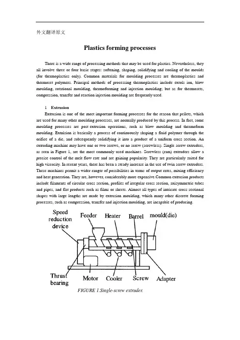
外文翻译原文Plastics forming processesThere is a wide range of processing methods that may be used for plastics. Nevertheless, they all involve three or four basic stages: softening, shaping, solidifying and cooling of the moulds (for thermoplastics only). Common materials for moulding processes are thermoplastics and thermoset polymers. Principal methods of processing thermoplastics include extols ion, blow moulding, rotational moulding, thermoforming and injection moulding; but as for thermosets, compression, transfer and reaction injection moulding are frequently used.1 ExtrusionExtrusion is one of the most important forming processes for the reason that pellets, which are used for many other moulding processes, are normally produced by this process. In fact, some moulding processes are post-extrusion operations, such as blow moulding and thermoform moulding. Extnlsion is basically a process of continuously shaping a fluid polymer through the orifice of a die, and subsequently solidifying it into a product of a uniform cross-section. An extruding machine may have one or two screws, or no screw (screwless). Single-screw extruders, as seen in Figure 1, are the most commonly used machines. Screwless (ram) extruders allow a precise control of the melt flow rate and are gaining popularity. They are particularly suited for high viscosity. In recent years, there has been a steady increase in the use of twin screw extruders. These machines permit a wider ranger of possibilities in terms of output rates, mixing efficiency and heat generation. They are, however, considerably more mon extrusion products include filaments of circular cross-section, profiles of irregular cross-section, axisymmetric tubes and pipes, and flat products such as films or sheets. Almost all types of intricate cross-sectional shapes with large lengths are made by extrusion moulding, which many other discrete forming processes, such as compression, transfer and injection moulding, are incapable of producing.FIGURE 1.Single-screw extruder.2 Blow mouldingThis process begins with the preparation of a soft, extruded and preformed thermoplastic tube over a core pin.As the mould halves close, air pressure inflates the thinwalled preform and forces it outwards against the mould sides. Figure 2 shows the process at two stages. The preform can be made by either extras ion or injection. Blow moulds are subjected to moderate pressures and clamping forces, compared to injection moulds. Thus, they can be made of a light material such as aluminmm, which has advantages of light weight and high heat conductivity.Blown-ware containers are commonly used for packaging beverage and other fluid food, e.g. narrow neck plastic bottles for mineral water, milk, alcoholic beverage and carbonated beverages. Other non-food products packed in the blown-ware containers include cosmetics, pharmaceuticals, paint and powder products. Blow moulding is also used to produce some huge products in size, such as shipping drums and stationary storage tanks whose volumes may reach as high as 10 000 litres [5]. These tanks are used for underground fuel storage and septic tanks.Stage 1: Preform extrusion Stage 2: BlowingFIGURE 2.Extrusion blow moulding3 Rotational mouldingLike blow moulding, rotational moulding is also used to produce hollow plastic articles, though the principles in each method differ a lot. During the process, a carefully weighed charge of plastic powder is placed in one half of a metal mould. The mould halves are then clamped together and heated on an oven. When heated, the mould rotates about two axes at right angles to each other. After a time the plastics will be sufficiently softened to form a homogeneous layer on the surface of the mould. The process is attractive for a number of reasons. Firstly, as it is a low-pressure process, the moulds are relatively simple and inexpensive. Secondly, the product is virtually strata-free. Thirdly, a uniform thickness can be easily achieved. Finally, it is possible to introduce reinforcement into the products, and their surface can be textured as desired. However, the cycle times are longer compared to blow or injection moulding. The mould-handling device, capable of imparting double rotations, is the central element of rotational moulding equipment. There are two major types of equipment: shuttle cart system, as shown Figure 3, and swing/rotary arm system. Rotational moulding is good at producing very large, thick-walled articles which could not be produced economically by any other processes. The largest capacity of arotational-moulding made tank is recorded at about 75 000 litres [4].FIGURE 3.Shuttle cart rotational moulding.The Institution of Professional Engineers New Zealand4 Compression mouldingCompression moulding is often used to produce articles from thermoset materials, though it can also be used for thermoplastics. The moulding operation used for thermosets is illustrated in Figure 4. A large number of compression moulded thermoset products can be found in electrical and electronic applications. Glass-fibre reinforcement can be easily added to meet the heat resistance requirement. However, the limitation with this process is that the product has to be simple in shape and without thin walls or fragile inserts. Numerous rubber products are compression moulded. A useful feature of it is its ability to have metal inserts that form strong bonds with the product and are often used to attach the product to structures. Tyres are the most common products made by compression moulding.FIGURE pression moulding.5 Transfer mouldingTransfer moulding is similar to compression moulding except that, instead of the moulding material being pressurised in the cavity, it is pressurised in a separate chamber and then forced through an opening and into a closed mould cavity. The advantage of transfer moulding is that thepreheating of the material injected through a narrow orifice improves the temperature distribution in the material and hence accelerates the cross-linking reaction in thermosets. As a result the cycle time is reduced and there is less distortion in the product. The improved flow of material also means that more intricate shapes can be produced. Parts with fragile inserts like electric appliance parts, electronic components and connectors that may enclose coils, integrated circuits, and plugs can also be easily made.6 ThermoformingSheet thermoforming was developed in the 1950s. The limitations such as poor wall thickness distribution and large peripheral waste restricted its use to simple packaging applications. In recent years, however, there have been major advances in machine design and materials, which have resulted in a wide range of products being made by thermoforming. There are three types of thermoforming processes (Figure 5): vacuum moulding, air pressure moulding, and mechanical moulding.The moulds, which are not subjected to high pressure, are often made from cast or machined alumininm for small and medium sizes, and they do not require a good surface finish. The product surface quality is largely dependent upon that of the sheet material.Products made by thermoforming can be small as well as large. Smaller products are made in high output machines, using multi-cavity moulds. Such products are often found in the food industry and medical applications, for example, jelly or cream containers, cups, robs and trays. These small items can have relatively complex shapes with reasonably even thickness. Large products are generally made from cut sheets at a lower though-put rate, and they are usually of simple shapes. Fisher & Paykel's vacuum form moulding machines produce the majority of pre-forms for refrigerators and freezers. Many other interior parts are also made by the same or similar processes.FIGURE 5.Three basic methods of thermoforming.7 Injection mouldingInjection moulding has always been one of the most common processing methods for plastics. Nowadays countless parts in many electrical appliances, automobiles and office equipment are injection moulded. The most common injection moulding machinery is the reciprocating screw machine, whose process can be divided into several stages as seen in Figure 6. At the plastication stage, the feed unit operates as an extntder, melting and homogenising the material in the screw/barrel system. The screw, however, is allowed to retract in order to make room for themolten material in a space at the cylinder head, called material reservoir, between the screw tip and a closed valve or an obstntction of solidified material from the previous shot. At the injection stage, the screw is used as a ram (piston) for rapid transfer of the molten material from the reservoir to the cavity between the two halves of the closed mould. Since the mould is kept at a temperature below the solidification temperature of the material, it is essential to inject the molten material rapidly enough to ensure complete filling of the cavity. A high holding or packing pressure is normally exerted, to partially compensate for the thermal contraction of the material upon cooling. The cooling of the material in the mould often limits the production time because of the low thermal conductivity of polymers. The mould, after being cooled, can be opened and the solid product ejected.Although the screw machine is by far the most popular, plunger injection machines are also used to give products some unique features. There is no shearing or mixing action, as a plunger does not rotate. The resulting moulded part can take on a marbled appearance with swirls of two or more colours. This may be the desired finish for certain products. Regardless of different machines, injection moulding yields a high productivity and allows the products to have many fine details such as bosses, location pins, mounting holes, bushings, ribs, flanges, etc. All these features can eliminate many subs equent assembly and finishing operations.A large variety of products can be injection moulded. These include (a) micro-products, moulded in multiple cavity moulds on small precision machines, such as components for watches and microelectronics; (b) medium size products, moulded continuously in very large numbers in dedicated machines or in relatively small runs; and (c) large products, moulded by large machines, such as car dashboard frames, TV cabinets, garden furniture, and small boat hulls. Many of these large plastic parts have a solid skin and a cellular inner structure, hence the process is also known as structural foam moulding.FIGURE 6.Sequence of operations in injection moulding.8 Reaction injection mouldingReaction injection moulding is a relatively new process, which involves the rapid mixing, in precise proportions, of two or more highly reactive liquid components and the immediate injection of the mixture in a closed mould Polymerisation takes place in the mould in a very short period oftime, yielding a solid product. The process is particularly suited to the production of large and relatively thin parts, with less capital investment and operating costs than in thermoplastic injection moulding. The process is also energy efficient, but requires good control of complex reactions.9 ConclusionsBy and large, each moulding process mentioned above has its pros and cons in terms of the materials, products and cost. The plastics industry plays an important role in today's manufacturing industry. Plastics moulding is the most popular process. Whereas injection moulding continues to dominate the sector, other moulding processes make some important contributions toward manufacture of many specific products. Faced by numerous challenges, new processes are making their way into the market. Conscious of energy consumption, moulding machine manufacturers are contemplating innovative designs to economise on the process. There is also a demand for these manufacturers to develop either smaller or larger moulding machines to meet customer demands. The fact that more and more newly developed materials use moulding processes for a manufacturing method provides an extra dimension for the development of the moulding industry.外文翻译译文塑料成型过程有很多关于塑料成型的方法。

汽车后视镜毕业设计论文(含外文翻译)工学学士学位论文汽车后视镜注塑模具设计2009年6月工学学士学位论文汽车后视镜注塑模具设计本科生:导师:申请学位级别:工学学士工程领域:机械工程所在单位:机械工程学院答辩日期:2009年6月授予学位单位:Dissertation for the Bachelor Degree of EngineeringPlastic Injection Mould Design of a Rearview Mirror of an AutomobileCandidate:Supervisor:Academic Degree Applied for:Bachelor of EngineeringProfessional Field:Mechanical Engineering Date of Oral Examination:March,2009University:汽车后视镜注塑模具设计摘要模具是工业生产中的重要工艺装备,是国民经济各部门发展的重要基础之一。
由于我国塑料工业的快速发展,特别是工程塑料的高速发展。
今后我国塑料模具的发展速度仍将继续高于模具工业的整体发展速度。
随着CAD/CAE/CAM软件智能化的高速发展,塑料制件及模具的3D设计与成型过程中的CAE分析,将在我国塑料模具工业中发挥越来越重要的作用。
本次设计的课题是“汽车后视镜的注塑模具设计”。
通过对其的工艺性分析,了解其生产技术要求,结合生产的实际环境和制造工艺性等,对其进行了注塑模具设计。
包括注塑成型工艺过程、分模面的设计、型腔设计、型芯设计、具体结构设计、零件工艺性分析、标准件的选用。
详细介绍了分型面、型腔布置、浇注系统、排气系统、加热、冷却系统、顶出机构、脱模机构以及主要零部件的设计过程。
在设计中采用了新的设计思想和新的设计流程,即在整个设计周期内使用使用相同的三维实体模型,以及使用一个基于知识库的三维辅助设计系统,从而降低了成本,缩短生产了周期,提高了生产效率。
外文翻译原文:Injection MoldingMany different processes are used to transform plastic granules, powders, and liquids into product. The plastic material is in moldable form, and is adaptable to various forming methods. In most cases thermosetting materials require other methods of forming. This is recognized by the fact that thermoplastics are usually heated to a soft state and then reshaped before cooling. Theromosets, on the other hand have not yet been polymerized before processing, and the chemical reaction takes place during the process, usually through heat, a catalyst, or pressure. It is important to remember this concept while studying the plastics manufacturing processes and polymers used.Injection molding is by far the most widely used process of forming thermoplastic materials. It is also one of the oldest. Currently injection molding accounts for 30% of all plastics resin consumption. Since raw material can be converted by a single procedure, injection molding is suitable for mass production of plastics articles and automated one-step production of complex geometries. In most cases, finishing is not necessary. Typical products include toys, automotive parts, household articles, and consumer electronics goods.Since injection molding has a number of interdependent variables, it is a process of considerable complexity. The success of the injection molding operation is dependent not only in the proper setup of the machine hydraulics, barrel temperature variations, and changes in material viscosity. Increasing shot-to-shot repeatability of machine variables helps produce parts with tighter tolerance, lowers the level of rejects, and increases product quality (i.e., appearance and serviceability).The principal objective of any molding operation is the manufacture of products: to a specific quality level, in the shortest time, and using repeatable and fully automaticcycle. Molders strive to reduce or eliminate rejected parts in molding production. For injection molding of high precision optical parts, or parts with a high added value such as appliance cases, the payoff of reduced rejects is high.A typical injection molding cycle or sequence consists of five phases;1. Injection or mold filling2. Packing or compression3. Holding4. Cooling5. Part ejectionPlastic granules are fed into the hopper and through an in the injection cylinder where they are carried forward by the rotating screw. The rotation of the screw forces the granules under high pressure against the heated walls of the cylinder causing them to melt. As the pressure building up, the rotating screw is forced backward until enough plastic has accumulated to make the shot. The injection ram (or screw) forces molten plastic from the barrel, through the nozzle, sprue and runner system, and finally into the mold cavities. During injection, the mold cavity is filled volumetrically. When the plastic contacts the cold mold surfaces, it solidifies (freezes) rapidly to produce the skin layer. Since the core remains in the molten state, plastic follows through the core to complete mold filling. Typically, the cavity is filled to 95%~98% during injection. Then the molding process is switched over to the packing phase.Even as the cavity is filled, the molten plastic begins to cool. Since the cooling plastic contracts or shrinks, it gives rise to defects such as sink marks, voids, and dimensional instabilities. To compensate for shrinkage, addition plastic is forced into the cavity. Once the cavity is packed, pressure applied to the melt prevents molten plastic inside the cavity from back flowing out through the gate. The pressure must be applied until the gate solidifies. The process can be divided into two steps (packing and holding) or may be encompassed in one step(holding or second stage). During packing, melt forced into the cavity by the packing pressure compensates for shrinkage. With holding, the pressure merely prevents back flow of the polymer malt.After the holding stage is completed, the cooling phase starts. During, the part is held in the mold for specified period. The duration of the cooling phase depends primarily on the material properties and the part thickness. Typically, the part temperature must cool below the material’s ejection temperature. While cooling the part, the machine plasticates melt for the next cycle.The polymer is subjected to shearing action as well as the condition of the energy from the heater bands. Once the short is made, plastication ceases. This should occur immediately before the end of the cooling phase. Then the mold opens and the part is ejected.When polymers are fabricated into useful articles they are referred to as plastics, rubbers, and fibers. Some polymers, for example, cotton and wool, occur naturally, but the great majority of commercial products are synthetic in origin. A list of the names of the better known materials would include Bakelite, Dacron, Nylon, Celanese, Orlon, and Styron.Previous to 1930 the use of synthetic polymers was not widespread. However, they should not be classified as new materials for many of them were known in the latter half of the nineteenth century. The failure to develop them during this period was due, in part, to a lack of understanding of their properties, in particular, the problem of the structure of polymers was the subject of much fruitless controversy.Two events of the twentieth century catapulted polymers into a position of worldwide importance. The first of these was the successful commercial production of the plastic now known as Bakelite. Its industrial usefulness was demonstrated in1912 and in the next succeeding years. Today Bakelite is high on the list of important synthetic products. Before 1912 materials made from cellulose were available, but their manufacture never provided the incentive for new work in the polymer field such as occurred after the advent of Bakelite. The second event was concerned with fundamental studies of the nature polymers by Staudinger in Europe and by Carohers, who worked with the Du Pont company in Delaware. A greater part of the studies were made during the 1920’s. Staudinger’s work was primarily fundamental. Carother’s achievements led to the development of our present huge plastics industry by causing an awakening of interest in polymer chemistry, an interest which is still strongly apparent today.The Nature of ThermodynamicsThermodynamics is one of the most important areas of engineering science used to explain how most things work, why some things do not the way that they were intended, and why others things just cannot possibly work at all. It is a key part of the science engineers use to design automotive engines, heat pumps, rocket motors, power stations, gas turbines, air conditioners, super-conducting transmission lines, solar heating systems, etc.Thermodynamics centers about the notions of energy, the idea that energy is conserved is the first low of thermodynamics. It is starting point for the science of thermodynamics is entropy; entropy provides a means for determining if a process is possible.This idea is the basis for the second low of thermodynamics. It also provides the basis for an engineering analysis in which one calculates the maximum amount of useful that can be obtained from a given energy source, or the minimum amount of power input required to do a certain task.A clear understanding of the ideas of entropy is essential for one who needs to use thermodynamics in engineering analysis. Scientists are interested in using thermodynamics to predict and relate the properties of matter; engineers are interested in using this data, together with the basic ideas of energy conservation and entropy production, to analyze the behavior of complex technological systems.There is an example of the sort of system of interest to engineers, a large central power stations. In this particular plant the energy source is petroleum in one of several forms, or sometimes natural gas, and the plant is to convert as much of this energy as possible to electric energy and to send this energy down the transmission line.Simply expressed, the plant does this by boiling water and using the steam to turn a turbine which turns an electric generator.The simplest such power plants are able to convert only about 25 percent of the fuel energy to electric energy. But this particular plant converts approximately 40 percent;it has been ingeniously designed through careful application of the basic principles of thermodynamics to the hundreds of components in the system.The design engineers who made these calculations used data on the properties of steam developed by physical chemists who in turn used experimental measurements in concert with thermodynamics theory to develop the property data.Plants presently being studied could convert as much as 55 percent of the fuel energy to electric energy, if they indeed perform as predicted by thermodynamics analysis.The rule that the spontaneous flow of heat is always from hotter to cooler objects is a new physical idea. There is noting in the energy conservation principle or in any other law of nature that specifies for us the direction of heat flow. If energy were to flow spontaneously from a block of ice to a surrounding volume of water, this could occur in complete accord with energy conservation. But such a process never happens. This idea is the substance of the second law of thermodynamics.Clear, a refrigerator, which is a physical system used in kitchen refrigerators, freezers, and air-conditioning units must obey not only the first law (energy conservation) but the second law as well.To see why the second law is not violated by a refrigerator, we must be careful in our statement of law. The second law of thermodynamics says, in effect, that heat never flows spontaneously from a cooler to a hotter object.Or, alternatively, heat can flow from a cooler to a hotter object only as a result of work done by an external agency. We now see the distinction between an everyday spontaneous process, such as the flow of heat from the inside to the outside of a refrigerator.In the water-ice system, the exchange of energy takes place spontaneously and the flow of heat always proceeds from the water to the ice. The water gives up energy and becomes cooler while the ice receives energy and melts.In a refrigerator, on the other hand, the exchange of energy is not spontaneous. Work provided by an external agency is necessary to reverse the natural flow of heat and cool the interior at the expense of further heating the warmer surroundings.译文:塑料注射成型许多不同的加工过程习惯于把塑料颗粒、粉末和液体转化成最终产品。
本科毕业设计(论文)外文翻译(附外文原文)学院:机械与控制工程学院课题名称:复杂阶梯形圆筒件拉深有限元分析专业(方向):机械设计制造及其自动化(模具设计与制造)班级:学生:指导教师:日期:拉伸模设计中拉伸壁起皱的分析摘要本文研究带有斜度的方形盒和带有阶梯的方形盒的拉深中发生的起皱现象。
这两种类型的起皱现象有一个共同的特征:全都发生在相对无支撑、无压边的拉深壁处。
在带有斜度的方形盒的拉深中,常受到工序参数的影响,例如:模具的间隙值和压边力等,所以常用有限元模拟的方法来研究分析起皱的发生。
模拟的结果表明模具的间隙值越大,起皱现象就越严重,而且增加压边力也不能抑制和消除起皱现象的发生。
在带有阶梯的方形盒拉深的起皱现象分析中,常通过实际生产中一种近似的几何结构来研究、试验。
当凸模与阶梯边缘之间的金属板料在拉深时分布并不均衡,就会在侧壁发生起皱现象。
为了消除起皱现象的发生,一个最优的模具设计常采用有限元的方法进行分析。
模拟的结果和起皱试验论证了有限元分析的准确性,并且表明了在拉深模具设计中使用有限元方法分析的优越性。
关键词:侧壁起皱;拉深模;带有阶梯的方形盒;带有斜度的方形盒1 引言起皱是金属板料成形中常见的失效形式之一。
由于功能和视觉效果的原因,起皱通常是不能为零件制品所能接受的。
在金属板料成形加工中通常存在三种类型的起皱现象:法兰起皱;侧壁起皱和由于残余压应力在未变形区产生的弹性变形。
在冲压复杂形状的时候,拉深壁起皱就是在模具型腔中形成的褶皱。
由于金属板料在拉深壁区域内相对无支撑,因此,消除拉深壁起皱比抑制法兰起皱要难得多。
我们知道在不被支撑的拉深壁区域中材料的外力拉深可以防止起皱,这可以在实践中通过增加压边力而实现,但是运用过大的拉深力会引起破裂失效。
因此,压边力必须控制在一定的范围内,一方面可以抑制起皱,另一方面也可以防止破裂失效。
合适的压边力范围是很难确定的,因为起皱在拉深零件的中心区域以一个复杂的形状形成,甚至根本不存在一个合适的压边力范围。
冲压模具设计毕业外文翻译中英文翻译外文文献翻译毕业设计(论文)外文资料翻译系部:专业:姓名:学号:外文出处: The Pofessional English of DesignManufacture for Dies & Moulds附件: 1.外文资料翻译译文,2.外文原文。
指导教师评语:签名:年月日附件1:外文资料翻译译文冲压模具设计对于汽车行业与电子行业,各种各样的板料零件都是有各种不同的成型工艺所生产出来的,这些均可以列入一般种类“板料成形”的范畴。
板料成形(也称为冲压或压力成形)经常在厂区面积非常大的公司中进行。
如果自己没有去这些大公司访问,没有站在巨大的机器旁,没有感受到地面的震颤,没有看巨大型的机器人的手臂吧零件从一个机器移动到另一个机器,那么厂区的范围与价值真是难以想象的。
当然,一盘录像带或一部电视专题片不能反映出汽车冲压流水线的宏大规模。
站在这样的流水线旁观看的另一个因素是观看大量的汽车板类零件被进行不同类型的板料成形加工。
落料是简单的剪切完成的,然后进行不同类型的加工,诸如:弯曲、拉深、拉延、切断、剪切等,每一种情况均要求特殊的、专门的模具。
而且还有大量后续的加工工艺,在每一种情况下,均可以通过诸如拉深、拉延与弯曲等工艺不同的成形方法得到所希望的得到的形状。
根据板料平面的各种各样的受应力状态的小板单元体所可以考虑到的变形情形描述三种成形,原理图1描述的是一个简单的从圆坯料拉深成一个圆柱水杯的成形过程。
图1 板料成形一个简单的水杯拉深是从凸缘型坯料考虑的,即通过模具上冲头的向下作用使材料被水平拉深。
一个凸缘板料上的单元体在半径方向上被限定,而板厚保持几乎不变。
板料成形的原理如图2所示。
拉延通常是用来描述在板料平面上的两个互相垂直的方向被拉长的板料的单元体的变形原理的术语。
拉延的一种特殊形式,可以在大多数成形加工中遇到,即平面张力拉延。
在这种情况下,一个板料的单元体仅在一个方向上进行拉延,在拉长的方向上宽度没有发生变化,但是在厚度上有明确的变化,即变薄。
![模具设计相关专业毕业论文(外文原文+翻译)之翻译[管理资料]](https://uimg.taocdn.com/63ac390ff705cc1754270968.webp)
可行成形图在汽车覆盖件冲压工艺高效设计的应用Dae-Cheol Ko a,Seung-Hoon Cha b,Sang-Kon Lee c,Chan-Joo Lee b,Byung-Min Kim d,*a ILIC, Pusan National University, 30 Jangjeon-Dong, Kumjeong-Gu, Busan609-735, South Koreab Precision Manufacturing Systems Division, Pusan National University, 30Jangjeon-Dong, Kumjeong-Gu, Busan 609-735, South Koreac PNU-IFAM, Joint Research Center, Pusan National University, 30Jangjeon-Dong, Kumjeong-Gu, Busan 609-735, South Koread School of Mechanical Engineering, Pusan National University, 30 Jangjeon-Dong, Kumjeong-Gu, Busan 609-735, South Korea摘要:本文提出使用可行的成形图来表示无断裂和起皱的安全区域,进而有效和快速地设计冲压工艺方法。
要确定可行的成形图,有限元分析对应于正交实验设计的过程变量组合。
随后,基于成形极限图的有限元分析,确定断裂和起皱的特征值。
所有组合的特征值在整个过程中,通过人工神经网络训练进行了一系列预测。
可行的成形图从所有组合的过程变量中最终确定。
以汽车覆盖件如转动架和车轮毂的冲压工艺作为实例来验证利用成形图的进行过程设计有效性。
有限元模拟结果与实验模拟结果比较表明,利用可行的成形图来进行冲压工艺的设计是有效的并适用于实际的过程。
附录外文资料TEMPERATURE CONTROLP. H. J. InghamMarketing Manager ,Eurotherm Ltd,Worthing,Sussex,UKSUMMARYCommercial plastic materials are organically based and are therefore heatsensitive .Accurate temperature control of melt processes such as injection moulding is therefore necessary if problems caused by thermal degradation are to be avoided. The injection moulding process is considered form a temperature controlriewpoint and some of the control methods or techniques are described.since it should not be forgotten that good temperature control can lend to materials and energy savings.1 INTRODUTIONThe injection moulding process is concerned with the efficient conversion of plastics raw material into moulded product ofacceptable standards.Some of ths parameters which determine acceptability are weight,dimensions,colour and stenght,all of which can be affected by the conditions under which the material is processed.Having established by the conditions for thwese parameters so as to deermine acceptability,limits can be set for the conditions under which the material is processed.One of the most important parameters contributing to the correct operation of an injection moulding machine is temperature.All plastics materials can be correctly processed only within a certain range of temperatures which varies from materialFor some mateials and mould types the band isvery small and for others it can be quite wide.Any attempt to define the limits within which the product is acceptable determines the need for some form of control.There are a number of types of control which,if applied correctly,can lead to adequate performance.Significant material and energy savings can be achieved by correctly pplying the right type of control equipment.The reliability of the system and the degree of operator supervision required also depend very largely on the balance struck between initial cost and performance.It is the purpose of this chapter to examine the injection moulding machine from a temperature control viewpoint andto outline some of the control methods can be used ,together with advantages and disadvantages.2 THE PROCESS2.1 Machine ZoningFrom a control viewpoint,an injection moulding machine consists of a number of zones (each equipped with a means of measauring the temperature) and a controller,which compares the measured value of the set-point and controls the heat input to the zone in such a way as to remove any different between the heat input to the zone in such a way as to remove any difference between the tow. Yu dividing the machine into a number of zones the different temperature requirements of different zones and their different heat input needs can most easily be met (Fig.1).For this purpose a typical small machine may have three or four barrel zones and a nozzle one. The zones nearest to the material feed hopper are where the plastic is melted and thus require fairly large heat inputs. However, in the zones hearest to the nozzle, the heat produced, by the rise in pressure needed to force the plastic into the mould, means that relatively little additional heat input is requied when themachine is running. Indeed, if the machine cycle very short, with some materials it may be that more heat is generated than required to maintain the temperature, which will then rise uncontrollably mless some form of additional cooling is applied.2.2 Thermocpuple LocationConsidering again the barrel zones:these consist of a metal arrel with wall thickness sufficient to withstand the high pressures produced during the mjection cycle. The most common form of heating is electrical and is ipplied using band heaters strapped around the barrel (Fig.2). A controller of any kind can only control the temperature at the point of measurement. Ideally this will be as deep into the barrel wall as possible, since it is the temperature of the plastic which is required and not that of the barrel. Plastic is a poor thermal conductor and depending on whether the net heat dow is into or out of the plastic, a thermocouple deep into the barrel wall will register a temperature above or below the actual temperature. If the measuring element is shallow or on the barrel surface, the difference between the measured and actual melt temperatures can be very large. For any given conditions of operation there will be a more or less fixed differencebetween the melt and measured temperatures and acceptable produce may be produced. If ,however, the conditions, e.g. machine speed or ambient temperature, change, this may give rise to a melt temperature which does not result in the production of acceptable product. It is therefore important to place the thermocouple as close to the melt as possible , i.e. deep the barrel.2.3 Temperature OvershootThe resultant system of an electrical band heater strapped around a thick walled barrel with a deep thermocouple is typical of most plastics processing machinery and present a number of control problems. Not only must stable control be achieved during normal running of the machine but acceptable start-up performance must also be achieved. The machine must be brought to its normal operating temperature as quickly as possible and preferably with no overshoot. (Overshoot is said to occur if the temperature is rising or falling at such a rate as it reaches set-point that it does not stop there but continues past by some amount before returning towards set-point again; see Fig.4.)The basic cause of temperature overshoot in the system ismultiple heattransfer lags, i.e. where the heat generated electrically first raises the temperature of the heater thermal mass and is then conducted from the second thermal mass to a third and so on, until the heat reaches the point of measurement which, as stated already, is as near as possible to the point in the process to be controlled.In the simplest cast of multiple heat transfer only two thermal masses would be significantly involved, namely those of the heater and the load. If the thermal mass of each is about the same, this tends to represent about the worst case for overshoots (and hence controllability). Poor heat transfer from heater to load worsens the situation, since the heater temperature (during start-up, for example)can then become very much higher than the load temperature; when the power to the heater is cut off the final temperature reached (ignoring heat losses and assuming equal thermal masses for heater and load) will be the mean of their respective temperatures at the instant when the power is cut off. Thus ,the overshoot in load temperature increases as the heat transfer becomes worse.A particularly bad case of overshoot (and controllability) occurs where heat is transferred through a considerable thickness of heat-conducting material. This is exactly thesituation which is presented by an injection machine barrel with deep set thermocouple. This sort of heat transfer represents in effect an infinite order multiple heat transfer: several minutes can elapse between switch-on of power and a significant change in thermocouple temperature. In fact the response has almost the appearance of a delay (i.e. transport lag ) although there is really a considerable difference between this heart-transfer lag and a true delay. During the time of the heart-transfer lag, heat is being fed into the barrel, so that even if the source of heat were switched off at the instant the deep thermocouple began to respond, the thermocouple temperature would continue to rise as the heat energy already fed in distributed itself evenly throughout the thickness of the barrel wall.A large part of the total lag can in practice be caused by the heart-transfer lag which occurs with a resistance heater. From the heater element thermal mass, via electrical insulation, to the outer surface of the barrel. For the lag through the barrel wall(or for any similar from the heat transfer) doubling the heart-transfer distance results in four times the lag. Iron, from which most injection machines are made, is a rather poor material for heat transfer: for example similar lag are obtainedin aluminium and iron when the distance in aluminium is five times greater.3. METHODS OF CONTROLLING TEMPERATURE3.1 Measuring the TemperatureThe first item in the control system to consider is the measuring element, of which there are tow basic electrical types: active and passive.The active type are thermocouples. There are formed by the junction of tow dissimilar metals and give an output voltage proportional to the difference in temperature between the thermocouple and the point of measurement (Fig.3). The fact that the millivolt output of the thermocouple in relation to temperatures is non-linear and that it depends on a stable reference temperature for comparison purposes are factors ,Which must be taken into account in the controller. Thermocouples are very robust mechanically. (This is an obvious advantage in the environment of the moulding shop.) They also exhibit good repeatability from example to example of the same type. The two most common types used in plastic processing are both base metal thermocouples and these are nickel chrome/nickel aluminium (Type K) and iron/jconstantan (Type J).The passive types rely on having a resistance which varies with temperature in a known manner and thus, when fed from a constant current upon temperature. Such elements do not require a reference temperature to be generated by the controller. The commonest are the platinum resistance thermometer (which occupies a larer volume than a thermocouple and is more fragile)and the thermistor(which operates on the same principle and has the same disadvantages).The thermocouple is by far the most common measuring elcment used in practice. The siting of the thermocouple will depend upon the degree of control required, as will the choice of controller.3.2 ON/OFF ControlThe simplest form of controller provides ON/OFF control of load power. The measured temperature is compared with the set-point and if it is too low, power is applied to the load; if it is too high the power is switched off. In practice there will be a small amount of hysteresis in the controller (mainly so that spurious noise signals on the thermocouple and effects due to mains regulation should not result in rapid ON/OFF chatteringof the load power control relay). If the thermocouple and heater are in very close proximity, i.e. there is no appreciable lag, the temperature will cycle with an amplitude somewhat in excess of the controller hysteresis and with the natural period of the system. There will inevitably be some overshoot on start-up because full power will be applied to the load until the set and actual temperatures become equal and any stored energy in the heater will continue to be transferred to the load even after switch-off. It can be seen that if the thermocouple is deep in the barrel (thus measuring the melt temperature more closely) the system lags will be considerably increased and the temperature cycling will be of a longer period and will become much larger. Similar comments apply to the start-up overshoot.Thus ,in the least demanding circumstances, an ON/OFF controller with a shallow thermocouple may give acceptable results. However, with the large heaters required to give short start-up overshoot will probably be unacceptable for all but the least demanding situations and will be worse if account is taken of correct siting of the thermocouple.The natural period of the system results from a combination of heater power and location, sensor location, and the thermal mass of the system.3.3 Proportional Control (P only)If we take an ON/OFF controller and force the switching of the output within the controller itself (with variable mark: space ratio)at a rate which is higher than the natural period, then we have proportional control. As the measured temperature approaches the set temperature, the relay will switch off(for a short time) the power supplied to the load. This point, at which just less than full power is applied to the load, is the lower edge of the ‘proportional band’. As the actual temperature approaches the set temperature more closely, less and les power is applied to the load until, when the two become equal, the power input is zero. It is general for the proportional band to be downscale of the set-point, i.e. at set-point the power fed to the load is zer..The proportional band is usually defined as a percentage of the controller set-point scale span. Since the power applied to the load is proportional to the error or difference between actual and measured temperature (a so-called error-actuated system),it follows that if any power is required to maintain the temperature there must be some error in the system. This error is known as offset or droop (Fig.5). Since, on start-up, the loadpower will first be switched off at a temperature below the set-point, the resultant overshoot will be reduced. With a sufficiently large proportional band and sufficiently rapid cycling of the output pow er (compared to the system’s natural frequency) the oscillations in temperature will cease eventually. However, this does not necessarily mean that there will be no sart-up overshoot in temperature, but only that the subsequent oscillation will decay to zero amplitude.英文翻译注塑模的温度调节系统商用塑料是最常用的,但它是热敏感性材料。
【关键字】毕业设计冲压模具毕业设计外文翻译篇一:模具外文文献及翻译The mold designing and manufacturingThe mold is the manufacturing industry important craft foundation, in our country,the mold manufacture belongs to the special purpose equipment manufacturingindustry. China although very already starts to make the mold and the use mold, but long-term has not formed the industry. Straight stabs 0 centuries 80's later periods, the Chinese mold industry only then drives into the development speedway. Recent years, not only the state-owned mold enterprise had the very big development, the threeinvestments enterprise, the villages and towns (individual) the mold enterprise'sdevelopment also rapid quietly.Although the Chinese mold industrial development rapid, but compares with thedemand, obviously falls short of demand, its main gap concentrates precisely to,large-scale, is complex, the long life mold domain. As a result of in aspect and so on mold precision, life, manufacture cycle and productivity, China and the international average horizontal and the developed country still had a bigger disparity, therefore, needed massively to import the mold every year .The Chinese mold industry must continue to sharpen the productivity, from now on will have emphatically to the profession internal structure adjustment and thestate-of-art enhancement. The structure adjustment aspect, mainly is the enterprise structure to the specialized adjustment, the product structure to center the upscale mold development, to the import and export structure improvement, center theupscale automobile cover mold forming analysis and the structure improvement, the multi-purpose compound mold and the compound processing and the laser technology in the mold design manufacture application, the high-speed cutting, the superfinishing and polished the technology, the information direction develops .The recent years, the mold profession structure adjustment and the organizationalreform step enlarges, mainly displayed in, large-scale, precise, was complex, the long life, center the upscale mold and the mold standard letter development speed is higher than the common mold product; The plastic mold and the compression casting mold proportion increases; Specialized mold factory quantity and its productivity increase;"The three investments" and the private enterprise develops rapidly; The joint stock system transformation step speeds up and so on. Distributes from the area looked,take Zhejiang Delta and Yangtze River delta as central southeast coastal areadevelopment quickly to mid-west area, south development quickly to north. Atpresent develops quickest, the mold produces the most centralized province isGuangdong and Zhejiang, places such as Jiangsu, Shanghai, Anhui and Shandong also has a bigger development in recent years.Although our country mold total quantity had at present achieved the suitable scale, the mold level also has the very big enhancement, after but design manufacture horizontal overall rise and fall industry developed country and so on Yu De, America, date, France, Italy many. The current existence question and the disparity mainly display in following several aspects:(1) The total quantity falls short of demandDomestic mold assembling one rate only, about 70%. Low-grade mold, centerupscale mold assembling oneself rate only has 50% about.(2) the enterprise organizational structure, the product structure, the technical structure and the import and export structure does not gatherin our country mold production factory to be most is from the labor mold workshop which produces assembles oneself (branch factory), from produces assembles oneself the proportion to reach as high as about 60%, but the overseas mold ultra 70% is the commodity mold. The specialized mold factory mostly is "large and complete","small and entire" organization form, but overseas mostly is "small but", "is specially small and fine". Domestic large-scale, precise, complex, the long life mold accountsfor the total quantity proportion to be insufficient 30%, but overseas in 50% aboveXX years, ratio of the mold import and export is 3.7:1, the import and exportbalances the after net import volume to amount to 1.32 billion US dollars, is world mold net import quantity biggest country .(3) The mold product level greatly is lower than the international standardThe production cycle actually is higher than the international water broad productlevel low mainly to display in the mold precision, cavity aspect and so on surface roughness, life and structure.(4) Develops the ability badly, economic efficiency unsatisfactory our countrymold enterprise technical personnel proportion lowThe level is lower, also does not take the product development, and is frequent inthe passive position in the market. Our country each mold staff average year creation output value approximately, ten thousand US dollars, overseas mold industry developed country mostly 15 to10, 000 US dollars, some reach as high as 25 to10,000 US dollars, relative is our country quite part of molds enterprises also continuesto use the workshop type management with it, truly realizes the enterprise which the modernized enterprise manages fewTo create the above disparity the reason to be very many, the mold long-term hasnot obtained the value besides the history in as the product which should have, as well as the most state-owned enterprises mechanism cannot adapt the market economy, butalso has the following several reasons: .(1) Country to mold industry policy support dynamics also insufficientlyAlthough the country already was clear about has promulgated the mold profession industrial policy, but necessary policy few, carried out dynamics to be weak. Atpresent enjoyed the mold product increment duty enterprise nation 185; the majority enterprise still the tax burden is only overweight. The mold enterprise carries on the technological transformations introduction equipment to have to pay the considerable amount the tax money, affects the technology advancement, moreover privately operated enterprise loan extremely difficult.(2) Talented person serious insufficient, the scientific research development and the technical attack investment too urinemold profession is the technology, the fund, the work crowded industry, along withthe time progress and the technical development, grasps the talented person which and skilled utilizes the new technology exceptionally short, the high-quality mold fitterand the enterprise management talent extremely is also anxious. Because the mold enterprise benefit unsatisfactory and takes insufficiently the scientific research development and the technical attack, the scientific research unit and the universities, colleges and institutes eye stares at is creating income, causes the mold profession invests too few in the scientific research development and the technical attack aspect, causes the mold technological development step doe not to be big, progresses does not be quick.(3) The craft equipment level is low, also is not good, the using factor is low.Recent years ,our country engine bed profession progressed quickly, has been able to provide the quite complete precision work equipment, but compared with the overseas equipment, still had a bigger disparity. Although the domestic many enterprises have introduced many overseas advanced equipment, but the overall equipment level low are very more than the overseas many enterprises. As a result of aspect the and so on system and fund reason, introduces the equipment not necessary, the equipment and the appendix not necessary phenomenon are extremely common, the equipment utilization rate low question cannot obtain the comparatively properly solution for a long time .(4) Specialization, standardization, commercialized degree low, the cooperationabilityBecause receives "large and complete" "small and entire" the influence since long ago, mold specialization level low, the specialized labor division is not careful, the commercialized degree is low. At present domestic every year produces mold, commodity mold minister 40% about, other for from produce uses for oneself. Between the molds enterprise cooperates impeded, completes the comparativelylarge-scale mold complete task with difficulty. Mold standardization level low, mold standard letter use cave rare is low also to the mold quality, the cost has a more tremendous influence, specially has very tremendous influence.(5) To the mold manufacture cycle) the mold material and the mold correlationtechnology fallThe mold material performance, the quality and the variety question often canaffect the mold quality, the life and the cost, the domestically produced molding toolsteel and overseas imports the steel products to compare has a bigger disparity. Plastic, plate, equipment energy balance, also direct influence mold level enhancement.At present, our country economy still was at the high speed development phase, onthe international economical globalization development tendency is day by dayobvious, this has provided the good condition and the opportunity for the our countrymold industry high speed development. On the one hand, the domestic mold marketwill continue high speed to develop, on the other hand, the mold manufacture also gradually will shift as well as the transnational group to our country carries on themold purchase trend to our country extremely to be also obvious. Therefore, will takea broad view the future, international, the domestic mold market overall development tendency prospect will favor, estimated the Chinese mold will obtain the high speed development under the good market environment, our country not only can becomethe mold great nation, moreover certainly gradually will make the powerful nation tothe mold the ranks to make great strides forward. "15" period, the Chinese moldindustry level not only has the very big enhancement in the quantity and the archerytarget aspect, moreover the profession structure, the product level, the development innovation ability, enterprise's system and the mechanism as well as the technology advancement aspect also can obtain a bigger development .The mold technology has gathered the machinery, the electron, chemistry, optics,the material, the computer, the precise monitor and the information network and so on many disciplines, is a comprehensive nature multi-disciplinary systems engineering.The mold technology development tendency mainly is the mold product tolarger-scale, precise, more complex and a more economical direction develops, themold product technical content unceasingly enhances, the mold manufacture cycle unceasingly reduces, the mold production faces the information, is not having thechart, is fine, the automated direction develops, the mold enterprise to the technical integration, the equipment excellent, is producing approves the brand, themanagement information, the management internationalization direction develops.Mold profession in "十15" period needs to solve the key essential technologyshould be the mold information, the digitized technology and precise, ultra fine, high speed, the highly effective manufacture technology aspect breakthroughAlong with thenational economy total quantity and the industry product technologyunceasing development, all the various trades and occupations to the mold demandquantity more and more big, the specification more and more is also high.Although mold type many, but its development should be with emphasis both canmeet the massive needs, and has the comparatively high-tech content, specially atpresent domestic still could not be self-sufficient, needs the massive imports the moldand can represent the development direction large-scale, precise, is complex, the long篇二:冲压模具设计毕业设计开题报告题目:院系:专业:学生:学号:指导老师:毕业设计开题报告冲压工艺分析与弯曲冲孔模具的设计三峡大学机械与材料学院机械设计制造及其自动化三峡大学机械与材料学院冲压工艺分析与弯曲冲孔模具的设计开题报告一、课题的来源课题来源于生产实际,探讨冲压加工中较常见零件的工艺方法和结构设计。

abrasive grinding 强力磨削abrasive 磨料的,研磨的absence 不在,缺席accesssory 附件accommodate 适应accordingly 因此,从而,相应地accuracy 精度,准确性actuate 开动(机器),驱动adequate 足够的adhesive 粘合剂adjacent 邻近的adopt 采用advance 进步advisable 可取的agitate 摇动a large extent 很大程度algorithm 算法align 定位,调准alignment 校直all-too-frequent 频繁allowance 容差,余量alternate 交替,轮流alternatively 做为选择,也许aluminiun 铝ample 充足的analysis 分析ancillary 补助的,副的angular 有角的annealing 退火aperture 孔applied loads 作用力appropriate 适当的arc 弧,弓形arise 出现,发生arrange 安排article 制品,产品ascertain 确定,查明assemble 组装attitude 态度auxiliary 辅助的avoid 避免axis 轴axle 轮轴,车轴alternative 替换物backup 备份batch 一批bearing 轴承,支座bed 床身behavior 性能bench-work 钳工工作bend 弯曲beneath 在•••下bin 仓,料架blank 坯料blank 冲裁,落料blanking 落料模blast 一阵(风)blemish 缺点,污点bolster 模座,垫板boring 镗削,镗孔bracket 支架brass 黄铜break down 破坏breakage 破坏brine 盐水brittle 易碎的buffer 缓冲器built-in 内装的bulging 凸肚burr 毛刺bush 衬套by far •••得多,最by means of 借助于boost 推进cabinet 橱柜call upon 要求carbide 碳化物carburzing 渗碳carriage 拖板,大拖板carry along 一起带走carry down over 从•••上取下carry out 完成case hardening 表面硬化case 壳,套cast steel 铸钢casting 铸造,铸件category 种类caution 警告,警示cavity and core plates 凹模和凸模板cavity 型腔,腔,洞centre-drilling 中心孔ceramic 陶瓷制品chain doted line 点划线channel 通道,信道characteristic 特性check 核算chip 切屑,铁屑chuck 卡盘chute 斜道circa 大约circlip (开口)簧环circuit 回路,环路circulate (使)循环clamp 夹紧clamp 压板clay 泥土clearance 间隙clip 切断,夹住cold hobbing 冷挤压cold slug well 冷料井collapse 崩塌,瓦解collapsible 可分解的combination 组合commence 开始,着手commence 开始commercial 商业的competitive 竞争的complementary 互补的complexity 复杂性complication 复杂化compression 压缩comprise 包含compromise 妥协,折衷concern with 关于concise 简明的,简练的confront 使面临connector 连接口,接头consequent 随之发生的,必然的console 控制台consume 消耗,占用consummate 使完善container 容器contingent 可能发生的CPU (central processing unit) 中央处理器conventional 常规的converge 集中于一点conversant 熟悉的conversion 换算,转换conveyer 运送装置coolant 冷却液coordinate (使)协调copy machine 仿形(加工)机床core 型芯,核心corresponding 相应的counteract 反作用,抵抗couple with 伴随contour 轮廓crack (使)破裂,裂纹critical 临界的cross-hatching 剖面线cross-section drawn 剖面图cross-slide 横向滑板CRT (cathoder-ray tube) 阴极射线管crush 压碎cryogenic 低温学的crystal 结晶状的cubic 立方的,立方体的cup (使)成杯状,引伸curable 可矫正的curvature 弧线curve 使弯曲cutter bit 刀头,刀片cyanide 氰化物complicated 复杂的dash 破折号daylight 板距decline 下落,下降,减少deform (使)变形demonstrate 证明depict 描述deposite 放置depression 凹穴descend 下降desirable 合适的detail 细节,详情deterioration 退化,恶化determine 决定diagrammmatic 图解的,图表的dictate 支配die 模具,冲模,凹模dielectric 电介质die-set 模架digital 数字式数字dimensional 尺寸的,空间的discharge 放电,卸下,排出discharge 卸下discrete 离散的,分立的dislodge 拉出,取出dissolution 结束distinct 不同的,显著的distort 扭曲distort (使)变形,扭曲distributed system 分布式系统dowel 销子dramaticlly 显著地drastic 激烈的draughting 绘图draughtsman 起草人drawing 制图drill press 钻床drum 鼓轮dual 双的,双重的ductility 延展性dynamic 动力的edge 边缘e.g.(exempli gratia) [拉]例如ejector 排出器ejector plate 顶出板ejector rob 顶杆elasticity 弹性electric dicharge machining 电火花加工electrode 电极electro-deposition 电铸elementary 基本的eliminate 消除,除去elongate (使)伸长,延长emerge 形成,显现emphasise 强调endeavour 尽力engagement 约束,接合enhance 提高,增强ensure 确保,保证erase 抹去,擦掉evaluation 评价,估价eventually 终于evolution 进展excecution 执行,完成execute 执行electrochemical machining 电化学加工exerte 施加experience 经验explosive 爆炸(性)的extend 伸展external 外部的extract 拔出extreme 极端extremely 非常地extremity 极端extrusion 挤压,挤出envisage 设想Fahrenheit 华氏温度fabricate 制作,制造flat-panel technology 平面(显示)技术facility 设备facing 端面车削fall within 属于,适合于fan 风扇far from 毫不,一点不,远非fatigue 疲劳feasible 可行的feature 特色,特征feed 进给feedback 反馈female 阴的,凹形的ferrule 套管file system 文件系统fitter 装配工,钳工fix 使固定,安装fixed half and moving half 定模和动模facilitate 帮助flexibility 适应性,柔性flexible 柔韧的flow mark 流动斑点follow-on tool 连续模foregoing 在前的,前面的foretell 预测,预示,预言forge 锻造forming 成型four screen quadrants 四屏幕象限fracture 破裂free from 免于gap 裂口,间隙gearbox 齿轮箱govern 统治,支配,管理grain 纹理graphic 图解的grasp 抓住grid 格子,网格grind 磨,磨削,研磨grinding 磨光,磨削grinding machine 磨床gripper 抓爪,夹具groove 凹槽guide bush 导套guide pillar 导柱guide pillars and bushes 导柱和导套handset 电话听筒hardness 硬度hardware 硬件headstock 床头箱,主轴箱hexagonal 六角形的,六角的hindrance 障碍,障碍物hob 滚刀,冲头hollow-ware 空心件horizontal 水平的hose 软管,水管hyperbolic 双曲线的i.e. (id est) [拉]也就是identical 同样的identify 确定,识别idle 空闲的immediately 正好,恰好impact 冲击impart 给予implement 实现impossibility 不可能impression 型腔in contact with 接触in terms of 依据inasmuch (as) co因为,由于inch-to-metric conversions 英公制转换inclinable 可倾斜的inclusion 内含物inconspicuous 不显眼的incorporate 合并,混合indentation 压痕indenter 压头independently 独自地,独立地inevitably 不可避免地inexpensive 便宜的inherently 固有的injection mould 注塑模injection 注射in-line-of-draw 直接脱模insert 嵌件inserted die 嵌入式凹模inspection 检查,监督installation 安装integration 集成intelligent 智能的intentinonally 加强地,集中地interface 界面internal 内部的interpolation 插值法investment casting 熔模铸造irregular 不规则的,无规律irrespective of 不论,不管irrespective 不顾的,不考虑的issue 发布,发出joint line 结合线kerosene 煤油keyboard 健盘knock 敲,敲打lance 切缝lathe 车床latitude 自由lay out 布置limitation 限度,限制,局限(性) local intelligence 局部智能locate 定位logic 逻辑longitudinal 纵向的longitudinally 纵向的look upon 视作,看待lubrication 润滑machine shop 车间machine table 工作台machining 加工made-to-measure 定做maintenance 维护,维修majority 多数make use of 利用male 阳的,凸形的malfunction 故障mandrel 心轴manifestation 表现,显示massiveness 厚实,大块measure 大小,度量microcomputer 微型计算机microns 微米microprocessor 微处理器mild steel 低碳钢milling machine 铣床mineral 矿物,矿产minimise 把减到最少,最小化minute 微小的mirror image 镜像mirror 镜子moderate 适度的modification 修改,修正modulus 系数mold 模,铸模mold 制模,造型monitor 监控monograph 专著more often than not 常常motivation 动机mould split line 模具分型线moulding 注塑件move away from 抛弃multi-imprssion mould 多型腔模narrow 狭窄的NC (numerical control) 数控nevertheless 然而,不过nonferrous 不含铁的,非铁的normally 通常地novice 新手,初学者nozzle 喷嘴,注口numerical 数字的objectionable 有异议的,讨厌的observe 观察obviously 明显地off-line 脱机的on-line 联机operational 操作的,运作的opportunity 时机,机会opposing 对立的,对面的opposite 反面optimization 最优化orient 确定方向orthodox 正统的,正规的overall 全面的,全部的overbend 过度弯曲overcome 克服,战胜overlaping 重叠overriding 主要的,占优势的opposite 对立的,对面的pack 包装package 包装pallet 货盘panel 面板paraffin 石蜡parallel 平行的penetration 穿透peripheral 外围的periphery 外围permit 许可,允许pessure casting 压力铸造pillar 柱子,导柱pin 销,栓,钉pin-point gate 针点式浇口piston 活塞plan view 主视图plasma 等离子plastic 塑料platen 压板plotter 绘图机plunge 翻孔plunge 投入plunger 柱塞pocket-size 袖珍portray 描绘pot 壶pour 灌,注practicable 行得通的preferable 更好的,更可取的preliminary 初步的,预备的press setter 装模工press 压,压床,冲床,压力机prevent 妨碍primarily 主要地procedure 步骤,方法,程序productivity 生产力profile 轮廓progressively 渐进地project 项目project 凸出projection 突出部分proper 本身的property 特性prototype 原形proximity 接近prudent 谨慎的punch 冲孔punch shapper tool 刨模机punch-cum-blanking die 凹凸模punched tape 穿孔带purchase 买,购买push back pin 回程杆pyrometer 高温计quality 质量quandrant 象限quantity 量,数量quench 淬火radial 放射状的ram 撞锤rapid 迅速的rapidly 迅速地raster 光栅raw 未加工的raw material 原材料ream 铰大reaming 扩孔,铰孔recall 记起,想起recede 收回,后退recess 凹槽,凹座,凹进处redundancy 过多re-entrant 凹入的refer 指,涉及,谈及reference 参照,参考refresh display 刷新显示register ring 定位环register 记录,显示,记数regrind 再磨研relative 相当的,比较的relay 继电器release 释放relegate 把降低到reliability 可靠性relief valves 安全阀relief 解除relieve 减轻,解除remainder 剩余物,其余部分removal 取出remove 切除,切削reposition 重新安排represent 代表,象征reputable 有名的,受尊敬的reservoir 容器,储存器resident 驻存的resist 抵抗resistance 阻力,抵抗resolution 分辨率respective 分别的,各自的respond 响应,作出反应responsibility 责任restrain 抑制restrict 限制,限定restriction 限制retain 保持,保留retaining plate 顶出固定板reveal 显示,展现reversal 反向right-angled 成直角的rigidity 钢度rod 杆,棒rotate (使)旋转rough machining 粗加工rough 粗略的routine 程序rubber 橡胶runner and gate systems 流道和浇口系统sand casting 砂型铸造satisfactorily 满意地saw 锯子scale 硬壳score 刻划scrap 废料,边角料,切屑screwcutting 切螺纹seal 密封section cutting plane 剖切面secure 固定secure 紧固,夹紧,固定segment 分割sensitive 敏感的sequence 次序sequential 相继的seriously 严重地servomechanism 伺服机构servomotor 伺服马达setter 安装者set-up 机构sever 切断severity 严重shaded 阴影的shank 柄shear 剪,切shot 注射shrink 收缩side sectional view 侧视图signal 信号similarity 类似simplicity 简单single-point cutting tool 单刃刀具situate 使位于,使处于slide 滑动,滑落slideway 导轨slot 槽slug 嵌条soak 浸,泡,均热software 软件solid 立体,固体solidify (使)凝固solidify (使)固化solution 溶液sophisiticated 尖端的,完善的sound 结实的,坚固的spark erosion 火花蚀刻spindle 主轴spline 花键split 侧向分型,分型spool 线轴springback 反弹spring-loaded 装弹簧的sprue bush 主流道衬套sprue puller 浇道拉杆square 使成方形Servomechanism Laboratoies 伺服机构实验室stage 阶段standardisation 标准化startling 令人吃惊的steadily 稳定地step-by-step 逐步stickiness 粘性stiffness 刚度stock 毛坯,坯料storage tube display 储存管显示storage 储存器straightforward 直接的strain 应变strength 强度stress 压力,应力stress-strain 应力--应变stretch 伸展strike 冲击stringent 严厉的stripper 推板stroke 冲程,行程structrural build-up 结构上形成的sub-base 垫板subject 使受到submerge 淹没subsequent 后来的subsequently 后来,随后substantial 实质的substitute 代替,替换subtract 减,减去suitable 合适的,适当的suitably 合适地sunk 下沉,下陷superior 上好的susceptible 易受影响的sweep away 扫过symmetrical 对称的synchronize 同步,同时发生tactile 触觉的,有触觉的tailstock 尾架tapered 锥形的tapping 攻丝technique 技术tempering 回火tendency 趋向,倾向tensile 拉力的,可拉伸的tension 拉紧,张紧terminal 终端机terminology 术语,用辞theoretically 理论地thereby 因此,从而thermoplastic 热塑性的thermoplastic 热塑性塑料thermoset 热固性thoroughly 十分地,彻底地thread pitch 螺距thread 螺纹thrown up 推上tilt 倾斜,翘起tolerance 公差two-plate mould 双板式注射模tong 火钳tonnage 吨位,总吨数tool point 刀锋tool room 工具车间toolholder 刀夹,工具柄toolmaker 模具制造者toolpost grinder 工具磨床toolpost 刀架torsional 扭转的toughness 韧性trace 追踪transverse 横向的tray 盘,盘子,蝶treatment 处理tremendous 惊人的,巨大的trend 趋势trigger stop 始用挡料销tungsten 钨turning 车削twist 扭曲,扭转tracer-controlled milling machine 仿形铣床ultimately 终于undercut moulding 侧向分型模undercut 侧向分型undercut 底切underfeed 底部进料的undergo 经受underside 下面,下侧undue 不适当的,过度的uniform 统一的,一致的utilize 利用Utopian 乌托邦的,理想化的valve 阀vaporize 汽化vaporize (使)蒸发variation 变化various 不同的,各种的vector feedrate computation 向量进刀速率计算vee 字形velocity 速度versatile 多才多艺的,万用的vertical 垂直的via prep经,通过vicinity 附近viewpoint 观点wander 偏离方向warp 翘曲washer 垫圈wear 磨损well line 结合线whereupon 于是winding 绕,卷with respect to 相对于withstand 经受,经得起work 工件workstage 工序wrinkle 皱纹使皱yield 生产zoom 图象电子放大。
英文文献Mould designOVERVIEWWhile discussing the differences among engineers, scientists, and mathematicians in Chapter 1, we saw that the word engineering is related to both ingenious and devise .Creative design lies at the center of the mechanical engineering profession, and an engineer’s ultimate goal is to produce new hardware that solves one of society’s technical problems. Beginning either from a blank sheet of paper or from existing hardware that is being modified, the product development process oft en forms the focus of an engineer’s activities. I n keeping with their profession’s title, many engineers truly are ingenious, and they possess the vision and skill to make such lasting contributions as those described in the top ten list of Section 1.3 Formal education in engineering is not a prerequisite to having a good for a new or improved product. Your interest in studying mechanical engineering, in fact, may have been sparked by your own ideas for building hardware. The elements of mechanical engineering that we have examined up to this point-machine components and tools, forces in structures and fluids, materials and stresses, thermal and energy systems, and the motion of machinery-are intended to have set a foundation that will enable you to approach mechanical design in a more effective and systematic manner .IN that respect, approach the taken in this textbook is a condensed analog of the traditional engineering curriculum: Approximation, mathematics, and science are applied to design problems in order to increase performance and reduce trial and error. By applying the resources of Chapter2-7, you can select certain machine components and perform back-of-the-envelope calculation to guide design decisions. Such analyses are not made for their sake alone; rather, they enable you to design better and fast.Effective mechanical design is a broad area, and the creative and technical processes behind it cannot be set forth fully in one chapter-or even one textbook for that matter. Indeed, with this material as a starting point, you should continue to develop hands-on experience and design skills throughout your entire professional career. Even the most seasoned grapples with the procedure for transforming an idea into manufactured hardware that can be sold at a reasonable cost.After first discussing the hierarchy of steps that engineers take when they transform a new idea intoreality, we explore the subject of mechanical design through three case studies in the fields of conceptual design, computer-aided design, and detailed machine design. We will also discuss mechanical design from a business perspective and describe how patents protect newly developed technology. After completing this chapter, you should be able to:1)Outline the major steps and iteration in points in the high-level mechanical design procedure.2)Give an example of the processes for brainstorming and for identifying the advantages anddisadvantages of various design options3)Understand the role played by computer-aided engineering tools in mechanical design, anddescribe how such tools can be seamlessly integrated with one another.4)By using a sketch as a guide, describe the operation of an automobile automatic transmission, acomplex machine design that incorporates mechanical, electronic, computer, and hydraulic components.5)Explain what patents are, and discuss their importance to engineering’s business environment HIGH-LEVEL DESIGN PEOCEDUREIn this section, we outline the steps that engineers take when they develop new products and hardware. From the broadest viewpoint, design is defined as the systematic process for devising a mechanical system to meet one of society’s technical needs. The specific motivation could lie in the areas of transportation, communication, or security, for instance. The prospective product is expected to solve a particular problem so well, or offer such a new capability, that other will pay for it. Early on, a company’s marketing department will collaborate with engineers and managers to identify, in a general sense, new opportunities for products. Together, they define the new product’s concept by drawing upon feedback from potential customers and from user of related product. Designers will subsequently develop those concepts, work out the details, and bring the functioning hardware to realization. Many approximations, trade-offs, and choices are made along the way, and mechanical engineers are mindful that the level of precision that is need will naturally and gradually grow as the design matures. For instance, it does not make sense for an engineer to resolve specific details (should a grade 1020 or 1045 steel alloy be used? Are ball or roller bearings most appropriate? What must be the viscosity of the oil?) until the design's overall concept has taken firm shape. After all, at an early stage of the design cycle, the specifications for the product’s size, weight, power, or performance could still change. Design engineers are comfortablewith such ambiguity, and they are able to develop product even in the presence of requirements and constraints that can change.The formal procedure by which a marketing concept evolves into manufactured hardware is based upon many principles and attributes. Most engineers would probably agree that creativity, simplicity, and iteration are key factors in any successful endeavor. Innovation begins with a good idea, but also implies starting from a blank sheet of paper. Nevertheless, engineers must still take the first, perhaps uncertain, step for transforming that formative idea into concrete reality. Early design decisions are made by drawing upon a variety of source: personal experience, knowledge of mathematics and science, laboratory and field testing, and trial and error guided by good judgment. Generally speaking, simpler design concepts are better than complex ones, and the adage “keep it simple, stupid”has a well-deserved reputation among engineers for guiding decisions. Iteration is also important for improving a design and for refining hardware that works into hardware that works well. The first idea that you have, just like the first prototype that you construct, will probably not be the best ones that can be realized. With the gradual improvement of each iteration, however, the design will perform better, more efficiently, and more elegantly.From a macroscopic perspective, the mechanical design procedure can be broken down into four major steps, which are outlined with greater detail in Figure 8.1.1. Define and research objectives.Initially, a designer describes the new product’s requirements in terms of its function, weight, strength, cost, safety, reliability, and so forth. At this first stage, constraints that the design must satisfy are also established. Those constraints might be of a technical nature-say, a restriction on size or power consumption. Alternatively, the constraints could be related to business or marketing concerns, such as the product’s appearance, cost, or ease of use. When faced with a new technical challenge, engineers will conduct research and gather background information that is expected to be useful when concepts and details are later evaluated. Engineers read patents that have been issued for related technologies, consult with vendors of components or subsystems that might be used in the product, attend expositions and trade shows, and meet with potential customers to better understand the application. Early in the design process, engineers define the problem, set the objective, and gather pertinent information for the foundation of a good design.2. Generate concepts.In this stage, designers generally work in teams with the goal of devising a wide range of potential solutions to the problem at hand. This creative effort involves conceiving new ideas and combining previous ones to be greater than the sum of their parts. Hardware solutions are conceptualized and composed, and both good and not-so-good ideas are tossed about. Results from the brainstorming sessions are systematically recorded, the advantages and disadvantages of various solutions are identified, and trade-offs among the differing approaches are made. To document the suite of ideas that emerges from this synthesis stage, engineers sketch concepts, make notes, and prepare lists of “pros and cons”in their design notebooks. No particular idea is evaluated in depth, nor is any idea viewed with too critical an eye. Instead, you should focus on cataloging multiple approaches and devising a wide rang of design concepts, not necessarily all conventional ones. Even though a particular solution might not seem feasible at this early stage, should the product’s requirements or constraints change in the future (which is likely), the idea might in fact resurface as a leading contender.3. Narrow down the options.The design team further evaluates the concepts with a view toward reducing them to a promising few. For instance, engineers make preliminary calculations to compare strength, safety, cost, and reliability, and they will begin to discard the less feasible concepts. Sample hardware could also be produced at this stage. Just as a picture is worth a thousand words, a physical prototype is often useful for engineers to visualize complex machine components and to explain their assembly to others. The prototype can also be tested so that trade-off decisions are made based on the results of both measurements and analyses. One method for producing such components is called rapid prototyping, and its key capability is that complex, three-dimensional can be fabricated directly from is called fused deposition modeling, and it enables durables durable and fully functional prototypes to be fabricated from plastics and polycarbonates. As an example, Figure 8.2 depicts a computer-aided design drawing of an engine block and a physical prototype developed with the system show in Figure 8.34. Develop a detailed design.To reach this point of the high-level procedure, the design team will have brainstormed, tested, analyzed, and converged its way to what it perceives as the best concept. The implementation of the design, construction of a final prototype, and development of the manufacturing process each remain. Detailedtechnical issues are solved by applying mathematical, scientific, laboratory, and computer-aided engineering tools. Completed drawings and parts lists are prepared. The designers conduct engineering analysis and experiments to verify performance over a range of operating conditions. If necessary, changes to shape, dimensions, materials, and components will be made until all requirements and constraints are met. The design is documented through engineering drawings and written reports so that able to understand the reasons behind each of the many decisions that the designers made. Such documentation is also useful for future design teams to teams to learn from and build upon the present team’s experiences.At the most fundamental level, the final design must all of its requirements and constraints. You might thing that an engineer’s tasks are completed once the working prototype has been delivered or after the finishing touches have been applied to the drawings. However, mechanical engineers today work in a broader environment, and their hardware is viewed with a critical eye beyond the criterion of whether or not it functions as intended. For a product be successful, it must also be safe to use, reliable, environmentally sound in its use and disposal, and affordable to manufacture. After all, if the product is technically superb but it requires expensive materials and manufacturing operations, customers may avoid the product and select one that is more balanced in cost and performance. In the end, engineering is a business venture that must meet the needs of its customers.模具设计概况当我们在第1章讨论工程师,科学家和数学家之间不同的时候,我们看到工程学这个涉及到创意和设计两方面内容。
在塑料注射模具的设计中使用田口方法减少翘曲马来西亚,雪兰莪州,43400沙登,马来西亚博特拉大学,机械及制造工程系2004年9月3日收到,在2006年7月27日收到修订的形式,2006年10月接受摘要在当今的塑料行业中塑料注射成型是最重要的聚合物加工业务之一。
然而,模具制造和注塑机控制技术的不足将会导致有缺陷的塑料产品。
翘曲是缺陷的种类之一,通常出现在产品厚度小于1毫米中。
这个项目是要制作一个模具的生产薄板,尺寸120毫米× 50毫米× 1毫米。
薄板将用于翘曲测试。
在模具制作中,购买的模架将会被加工和组装。
在此之后,模具会被固定在注塑机上。
本机的设置应该能够生产出产品。
然后,该产品将会用于通过采用田口方法的实验设计来测试翘曲问题的影响因素。
根据结果,它表明对翘曲变形最有效的因素是熔体温度。
灌装时间只轻微影响翘曲。
可以最大限度地减少翘曲缺陷的最佳参数是熔融温度(240摄氏度),充盈时间(0.5秒),保压压力(90%)和包装时间(0.6 秒)。
埃尔塞维尔B.V,2006年,保留所有权利。
关键词:注塑模具;田口方法;实验设计;翘曲1. 简介模具制造是一项重要的支柱产业,因为其相关产品代表:超过70%的产品是消费类产品的组成部分。
为缩短设计和制造周期,良好的维和整体素质,高需求快速设计变更,已成为模具行业的瓶颈[1]。
这是一个复杂的过程,需要技术和经验丰富的模具制造者。
一般来说,在当今的塑料行业中注射成型是最重要的聚合物加工业务之一。
在所有的塑料中大约有三分之一的塑料转换成零件采用注射成型[2]。
这是有很大的可能被制造业首选的工艺之一,因为它生产的复杂形状塑料部件具有良好的尺寸准确度和极短的周期时间[3]。
典型的例子是计算机显示器和移动电话产品的肠衣和外壳,其中有一个壳薄功能。
这些产品往往会变得更轻,更薄,更小。
因此,产品的内部组件必须放进外壳中,它的体积更小。
增加外壳的内部空间的一种方法是减少壁体的厚度。
外文原文:Injection MoldsA. Basic mold designAn injection mold consists of at least two halves that are fastened to the two platens of the injection molding machine so that they can be opened and closed. In the closed position, the product-forming surfaces of the two mold halves define the mold cavity into which the plastic melt is injected via the runner system and the gate. Cooling provisions in the mold provide for cooling and solidification of the molded product so that it can be subsequently ejected.B. Types of EjectionFor product ejection to occur ,the mold must open. The shapes of the molded product determines whether it can be ejected simply by opening the two mold halves or whether undercuts must be present. The design of a mold is dictated primarily by the shape of the product to be molded and the provisions necessary for product ejection. Injection-molded products can be classified as:○1Products without undercuts(e.g., plaques, strips, half-shells, cups).○2Products with external undercuts or lateral openings(e.g., spools and bobbins, beverage crates, threaded bolts).○3Products with internal undercuts (e.g., threaded closures, housings).○4Products with external and internal undercuts(e.g., bumper fascias, electrical and automotive instrument housings, cameras, etc.).C. Design RulesThere are many rules for designing molds. These rules and standard practices are based on logic, past experience, convenience, and economy. For designing, mold making, and molding, it is usually of advantage to follow the rules. But occasionally, it may work out better if a rule is ignored and an alternative way is selected. In this text, the most common rules are noted, but the designer will learn only from experience which way to go. The designer must ever be open to mew ideas and methods, to new molding and mold materials that may affect these rules.D. The Basic Mold1. Mold Cavity SpaceThe mold cavity space is a shape inside the mold, ”excavated”(by machining the mold material) in such a manner that when the molding material(in our case, the plastic)is forced into this space it will take on the shape of the cavity space and, therefore, the desired product The principle of a mold is almost as old as human civilization. Molds have been used to make tools, weapons, bells, statues, and household articles, by pouring liquid metals (iron, bronze) into sand forms. such molds, which are still used today in foundries ,can be used only once because the mold is destroyed to release the product after it has solidified. Today, we are looking for permanent molds that can be used over and over .Now molds are made from strong, durable materials, such as steel, or from softer aluminum or metal alloys and even from certain plastics where a long mold life is not required because the planned production is small. In injection molding the (hot) plastic is injected into the cavity space with high pressure, so the mold must be strong enough to resist the injection pressure without deforming.2 . Number of CavitiesMany molds, particularly molds for larger products, are built for only 1 cavity space(a single-cavity mold),but many molds, especially large production molds, are built with or more cavities. The reason for this is purely economical. It takes only little more time to inject several cavities than to inject one. For example, a 4-cavity mold requires only (approximately) one-fourth of the machine time of a single-cavity mold. Conversely, the production increases in proportion to the number of cavities. A mold with more cavities is more expensive to build than a single-cavity mold, but (as in our example)not necessarily 4 times as much as a single-cavity mold .But it may also require a larger machine with larger platen area and more clamping capacity, and because it will use (in this example) 4 times the amount of plastic, it may need a larger injection unit, so the machine hour cost will be higher than for a machine larger enough for the smaller mold. Today, most multicavity molds are built with a preferred number of cavities:2,4,6,8,12,16,24,32,48,64,96,128.These numbers are selected because the cavities can be easily arranged in a rectangular pattern, which is easier for designing and dimensioning, or manufacturing, and for symmetry around the center of the machine, which is highly desirable to ensure equal clamping force for each cavity. A smaller number of cavities can also be laid out in a circular pattern, even with odd numbers of cavities, such as 3, 5, 7 , 9.It is also possible to make cavity layouts for any number of cavities, provided such rules as symmetry of the projected areas around the machine centerline are observed.3. Cavity Shape and ShrinkageThe shape of the cavity is essentially the ”negative” of the shape of the desired product, with dimensional allowances added to allow for shrinking of the plastic. The shape of the cavity is usually created with chip-removing machine tolls, or with electric discharge machining (EDM), with chemical etching, or by any new method that may be available to remove metal or build it up, such as galvanic processes. It may also be created by casting (and then machining) certain metals (usually copper or zinc alloys) in plaster molds created from models of the product to be made, or by casting (and then machining) some suitable hard plastics (e.g., epoxy resins).The cavity shape can be either cut directly into the mold plates or formed by putting inserts into the plates.E. Cavity and CoreBy convention, the hollow (concave) portion of the cavity space is called the cavity. The matching, often raised (or convex) portion of the cavity space is called the core. Most plastic products are cup-shaped. This does not mean that they look like a cup, but they do have an inside and an outside. The outside of the product is formed by the cavity, the inside by the core. The alternative to the cup shape is the flat shape. In this case, there is no specific convex portion, and sometimes, the core looks like a mirror image of the cavity. Typical examples for this are plastic knives, game chips, or round disks such as records. While these items are simple in appearance, they often present serious molding problems for ejection of the product. Usually, the cavities are placed in the mold half that is mounted on the injection side, while the cores are placed in the moving half of the mold. The reason for this is that all injection molding machines provide an ejection mechanism on the moving platen and the products tend to shrink onto and cling to the core, from where they are then ejected. Most injection molding machines do not provide ejection mechanisms on the injection (“hot”) side.中文译文:注塑模具A基本模具设计一个注塑模具至少包括两半,这些固定在两个盘的注塑机,以便他们能够开启和关闭。
模具毕业设计英译汉(Injection_molding)Injection moldingInjection molding (British English: moulding) is a manufacturing process for producing parts from both thermoplastic and thermosetting plastic materials. Material is fed into a heated barrel, mixed, and forced into a mold cavity where it cools and hardens to the configuration of the mold cavity.After a product is designed, usually by an industrial designer or an engineer, molds are made by a moldmaker (or toolmaker) from metal, usually either steel or aluminum, and precision-machined to form the features of the desired part. Injection molding is widely used for manufacturing a variety of parts, from the smallest component to entire body panels of cars.ApplicationsInjection molding is used to create many things such as wire spools, packaging, bottle caps, automotive dashboards, pocket combs, and most other plastic products available today. Injection molding is the most common method of part manufacturing. It is ideal for producing high volumes of the same object.Some advantages of injection molding are high production rates, repeatable high tolerances, the ability to use a wide range of materials, low labor cost, minimal scrap losses, and little need to finish parts after molding. Some disadvantages of this process are expensive equipment investment, potentially high running costs, and the need to design moldable parts.EquipmentPaper clip mold opened in molding machine; the nozzle is visible at rightMain article: Injection molding machineInjection molding machines consist of a material hopper, an injection ram or screw-type plunger, and a heating unit. They are also known as presses, they hold the molds in which the components are shaped. Presses are rated by tonnage, which expresses the amount of clamping force that the machine can exert. This force keeps the mold closed during the injection process. Tonnage can vary from less than 5 tons to 6000 tons, with the higher figures used in comparatively few manufacturing operations. The total clamp force needed is determined by the projected area of the part being molded. This projected area is multiplied by a clamp force of from 2 to 8 tons for each square inch of the projected areas. As a rule of thumb, 4 or 5 tons/in2 can be used for most products. If the plastic material is very stiff, it will require more injection pressure to fill the mold, thus more clamp tonnage to hold the mold closed. The required force can also be determined by the material used and the size of the part, larger parts require higher clamping force.MoldMold or die are the common terms used to describe the tooling used to produce plastic parts in molding.Since molds have been expensive to manufacture, they were usually only used in mass production where thousands of parts were being produced. Typical molds are constructed from hardened steel, pre-hardened steel, aluminum, and/or beryllium-copper alloy. The choice of material to build a mold from is primarily one of economics; in general, steel molds cost more to construct, but their longer lifespan will offset the higher initial cost over a higher number of parts made before wearing out. Pre-hardened steel molds are less wear-resistant and are used for lower volume requirements or larger components. The typicalsteel hardness is 38-45 on the Rockwell-C scale. Hardened steel molds are heat treated after machining. These are by far the superior in terms of wear resistance and lifespan. Typical hardness ranges between 50 and 60 Rockwell-C (HRC). Aluminum molds can cost substantially less, and, when designed and machined with modern computerized equipment, can be economical for molding tens or even hundreds of thousands of parts. Beryllium copper is used in areas of the mold that require fast heat removal or areas that see the most shear heat generated. The molds can be manufactured either by CNC machining or by using Electrical Discharge Machining processes.Mold DesignStandard two plates tooling –core and cavity are inserts in a mold base – "Family mold" of 5 different partsThe mold consists of two primary components, the injection mold (A plate) and the ejector mold (B plate). Plastic resin enters the mold through a sprue in the injection mold, the sprue bushing is to seal tightly against the nozzle of the injection barrel of the molding machine and to allow molten plastic to flow from the barrel into the mold, also known as cavity The sprue bushing directs the molten plastic to the cavity images through channels that are machined into the faces of the A and B plates. These channels allow plastic to run along them, so they are referred to as runners.The molten plastic flows through the runner and enters one or more specialized gates and into the cavity geometry to form the desired part.The amount of resin required to fill the sprue, runner and cavities of a mold is a shot. Trapped air in the mold can escape through air vents that are ground into the parting line of the mold. If the trapped air is not allowed to escape, it is compressedby the pressure of the incoming material and is squeezed into the corners of the cavity, where it prevents filling and causes other defects as well. The air can become so compressed that it ignites and burns the surrounding plastic material. To allow for removal of the molded part from the mold, the mold features must not overhang one another in the direction that the mold opens, unless parts of the mold are designed to move from between such overhangs when the mold opens (utilizing components called Lifters).Sides of the part that appear parallel with the direction of draw (The axis of the cored position (hole) or insert is parallel to the up and down movement of the mold as it opens and closes)are typically angled slightly with (draft) to ease release of the part from the mold. Insufficient draft can cause deformation or damage. The draft required for mold release is primarily dependent on the depth of the cavity: the deeper the cavity, the more draft necessary. Shrinkage must also be taken into account when determining the draft required.If the skin is too thin, then the molded part will tend to shrink onto the cores that form them while cooling, and cling to those cores or part may warp, twist, blister or crack when the cavity is pulled away. The mold is usually designed so that the moldedpart reliably remains on the ejector (B) side of the mold when it opens, and draws the runner and the sprue out of the (A) side along with the parts. The part then falls freely when ejected from the (B) side. Tunnel gates, also known as submarine or mold gate, is located below the parting line or mold surface. The opening is machined into the surface of the mold on the parting line. The molded part is cut (by the mold) from the runner system on ejection from the mold. Ejector pins, also known as knockout pin,is a circular pin placed in either half of the mold (usually the ejector half), which pushes the finished molded product, or runner system out of a mold.The standard method of cooling is passing a coolant (usually water) through a series of holes drilled through the mold plates and connected by hoses to form a continueous pathway. The coolant absorbs heat from the mold (which has absorbed heat from the hot plastic) and keeps the mold at a proper temperature to solidify the plastic at the most efficient rate.To ease maintenance and venting, cavities and cores are divided into pieces, called inserts, and sub-assemblies, also called inserts, blocks, or chase blocks. By substituting interchangeable inserts, one mold may make several variations of the same part.More complex parts are formed using more complex molds. These may have sections called slides, that move into a cavity perpendicular to the draw direction, to form overhanging part features. When the mold is opened, the slides are pulled away from the plastic part by using st ationary “angle pins” on the stationary mold half. These pins enter a slot in the slides and cause the slides to move backward when the moving half of the mold opens. The part is then ejected and the mold closes. The closing action of the mold causes the slides to move forward along the angle pins.Some molds allow previously molded parts to be reinserted to allow a new plastic layer to form around the first part. This is often referred to as overmolding. This system can allow for production of one-piece tires and wheels.2-shot or multi-shot molds are designed to "overmold" within a single molding cycle and must be processed on specialized injection molding machines with two or moreinjection units. This process is actually an injection molding process performed twice. In the first step, the base color material is molded into a basic shape. Then the second material is injection-molded into the remaining open spaces. That space is then filled during the second injection step with a material of a different color.A mold can produce several copies of the same parts in a single "shot". The number of "impressions" in the mold of that part is often incorrectly referred to as cavitation. A tool with one impression will often be called a single impression(cavity) mold.A mold with 2 or more cavities of the same parts will likely be referred to as multiple impression (cavity) mold.Some extremely high production volume molds (like those for bottle caps) can have over 128 cavities.In some cases multiple cavity tooling will mold a series of different parts in the same tool. Some toolmakers call these molds family molds as all the parts are related.Effects on the material propertiesThe mechanical properties of a part are usually little affected. Some parts can have internal stresses in them. This is one of the reasons why it's good to have uniform wall thickness when molding. One of the physical property changes is shrinkage. A permanent chemical property change is the material thermoset, which can't be remelted to be injected again.Tool MaterialsTool steel or beryllium-copper are often used. Mild steel, aluminum, nickel or epoxy are suitable only for prototype or very short production runs.Modern hard aluminum (7075 and 2024 alloys) with proper mold design, can easily make molds capable of 100,000 or more part life.Geometrical PossibilitiesThe most commonly used plastic molding process, injection molding, is used to create a large variety of products with different shapes and sizes. Most importantly, they can create products with complex geometry that many other processes cannot. There are a few precautions when designing something that willbe made using this process to reduce the risk of weak spots. First, streamline your product or keep the thickness relatively uniform. Second, try and keep your product between 2 to20 inches.The size of a part will depend on a number of factors (material, wall thickness, shape,process etc.). The initial raw material required may be measured in the form of granules, pellets or powders. Here are some ranges of the sizes.MachiningMolds are built through two main methods: standard machining and EDM. Standard Machining, in its conventional form, has historically been the method of building injection molds. With technological development, CNC machining became the predominant means of making more complex molds with more accurate mold details in less time than traditional methods.The electrical discharge machining (EDM) or spark erosion process has become widely used in mold making. As well as allowing the formation of shapes that are difficult to machine, the process allows pre-hardened molds to be shaped so that no heat treatment is required. Changes to a hardened mold by conventional drilling and milling normally require annealing to soften the mold, followed by heat treatment to harden it again. EDM is a simple process in which a shaped electrode, usuallymade of copper or graphite, is very slowly lowered onto the mold surface (over a period of many hours), which is immersed in paraffin oil. A voltage applied between tool and mold causes spark erosion of the mold surface in the inverse shape of the electrode.CostThe cost of manufacturing molds depends on a very large set of factors ranging from number of cavities, size of the parts (and therefore the mold), complexity of the pieces, expected tool longevity, surface finishes and many others. The initial cost is great, however the piece part cost is low, so with greater quantities the overall price decreases.Injection processSmall injection molder showing hopper, nozzle and die area With Injection Molding, granular plastic is fed by gravity from a hopper into a heated barrel. As the granules are slowly moved forward by a screw-type plunger, the plastic is forced into a heated chamber, where it is melted. As the plunger advances, the melted plastic is forced through a nozzle that rests against the mold, allowing it to enter the mold cavity through a gate and runner system. The mold remains cold so the plastic solidifies almost as soon as the mold is filled.Injection Molding CycleThe sequence of events during the injection mold of a plastic part is called the injection molding cycle. The cycle begins when the mold closes, followed by the injection of the polymer into the mold cavity. Once the cavity is filled, a holding pressure is maintained to compensate for material shrinkage. In the next step, the screw turns, feeding the next shot to the front screw.This causes the screw to retract as the next shot is prepared. Once thepart is sufficiently cool, the mold opens and the part is ejected.Molding trialWhen filling a new or unfamiliar mold for the first time, where shot size for that mold is unknown, a technician/tool setter usually starts with a small shot weight and fills gradually until the mold is 95 to 99% full. Once this is achieved a small amount of holding pressure will be applied and holding time increased until gate freeze off (solidification time) has occurred. Gate solidification time is an important as it determines cycle time, which itself is an important issue in the economics of the production process. Holding pressure is increased until the parts are free of sinks and part weight has been achieved. Once the parts are good enough and have passed any specific criteria, a setting sheet is produced for people to follow in the future. The method to setup an unknown mold the first time can be supported by installing cavity pressure sensors. Measuring the cavity pressure as a function of time can provide a good indication of the filling profile of the cavity. Once the equipment is set to successfully create the molded part, modern monitoring systems can save a reference curve of the cavity pressure. With that it is possible toreproduce the same part quality on another molding machine within a short setup time.Tolerances and SurfacesMolding tolerance is a specified allowance on the deviation in parameters such as dimensions, weights, shapes, or angles, etc. To maximize control in setting tolerances there is usually a minimum and maximum limit on thickness, based on the process used.Injection molding typically is capable of tolerances equivalent to an IT Grade of about 9–14. The possible toleranceof a thermoplastic or a thermoset is ±0.008 to ±0.002 inches. Surface finishes of two to four microinches or better are can be obtained. Rough or pebbled surfaces are also possible.Lubrication and CoolingObviously, the mold must be cooled in order for the production to take place. Because of the heat capacity, inexpensiveness, and availability of water, water is used as the primary cooling agent. To cool the mold, water can be channeled through the mold to account for quick cooling times. Usually a colder mold is more efficient because this allows for faster cycle times. However, this is not always true because crystalline materials require the opposite: a warmer mold and lengthier cycle time.InsertsMetal inserts can be also be injection molded into the workpiece. For large volume parts the inserts are placed in the mold using automated machinery. An advantage of using automated components is that the smaller size of parts allows a mobile inspection system that can be used to examine multiple parts in a decreased amount of time. In addition to mounting inspection systems on automated components, multiple axial robots are also capable of removing parts from the mold and place them in latter systems that can be used to ensure quality of multiple parameters. The ability of automated components to decrease the cycle time of the processes allows for a greater output of quality parts.Specific instances of this increased efficiency include the removal of parts from the mold immediately after the parts are created and use in conjunction with vision systems. The removal of parts is achieved by using robots to grip the partonce it has become free from the mold after in ejector pins have been raised. The robot then moves these parts into either a holding location or directly onto an inspection system, depending on the type of product and the general layout of the rest of the manufacturer's production facility. Visions systems mounted on robots are also an advancement that has greatly changed the way that quality control is performed in insert molded parts. A mobile robot is able to more precisely determine the accuracy of the metal component and inspect more locations in the same amount of time as a human inspector.注塑成型注射制模(Injection moldin)是一种生产由热塑性塑料或热固性塑料所构成的部件的过程。
毕业设计外文资料翻译 系 部: 机械工程系 专 业: 材料成型及控制工程 姓 名: 学 号: 外 文 出 处: http://www.sciencedirect.com
附 件: 1.外文资料翻译2.外文原文
2012年03月05日 一个描述电铸镍壳在注塑模具的应用的技术研究 ——Universidad de Las Palmas de Gran Canaria, Departamento de Ingenieria Mecanica, Spain
摘要: 在过去几年中快速成型技术及快速模具已被广泛开发利用. 在本文中,使用电芯作为核心程序对塑料注射模具分析. 通过差分系统快速成型制造外壳模型. 主要目的是分析电铸镍壳力学特征、 研究相关金相组织,硬度,内部压力等不同方面,由这些特征参数以生产电铸设备的外壳. 最后一个核心是检验注塑模具. 关键词:电镀;电铸;微观结构;镍 1. 引言 现代工业遇到很大的挑战,其中最重要的是怎么样提供更好的产品给消费者,更多种类和更新换代问题. 因此,现代工业必定产生更多的竞争性. 毫无疑问,结合时间变量和质量变量并不容易,因为他们经常彼此互为条件; 先进的生产系统将允许该组合以更加有效可行的方式进行,例如,如果是观测注塑系统的转变、 我们得出的结论是,事实上 一个新产品在市场上具有较好的质量它需要越来越少的时间 快速模具制造技术是在这一领域, 中可以改善设计和制造注入部分的技术进步. 快速模具制造技术基本上是一个中小型系列的收集程序,在很短的时间内在可接受的精度水平基础上让我们获得模具的塑料部件。其应用不仅在更加广阔而且生产也不断增多。 本文包括了很广泛的研究路线,在这些研究路线中我们可以尝试去学习,定义,分析,测试,提出在工业水平方面的可行性,从核心的注塑模具制造获取电铸镍壳,同时作为一个初始模型的原型在一个FDM设备上的快速成型。 不得不说的是,先进的电铸技术应用在无数的行业,但这一研究工作调查到什么程度,并根据这些参数,使用这种技术生产快速模具在技术上是可行的. 都产生一个准确的,系统化使用的方法以及建议的工作方法. 2 制造过程的注塑模具 薄镍外壳的核心是电铸,获得一个充满epoxic金属树脂的一体化的核心板块模具(图1)允许直接制造注射型多用标本,因为它们确定了新英格兰大学英文国际表卓华组织3167标准。这样做的目的是确定力学性能的材料收集代表行业。 该阶段取得的核心[4],根据这一方法研究了这项工作,有如下: a,用CAD系统设计的理想对象 b模型制造的快速成型设备(频分多路系统). 所用材料将是一个ABS塑料 c一个制造的电铸镍壳,已事先涂有导电涂料(必须有导电). d无外壳模型 e核心的生产是背面外壳环氧树脂的抗高温与具有制冷的铜管管道. 有两个腔的注塑模具、 其中一个是电核心和其他直接加工的移动版. 因此,在同一工艺条件下,同时注入两个标准技术制造,获得相同的工作。 3 获得电壳:设备 电镀是电解质时电流的化学变化,电解所形成的直流电有两个电极,阳极和阴极。当电流流经电路,在离子溶液中转化为原子。 电镀液用于这项工作是由氨基磺酸镍400 毫升/升,氯化镍(10克/升)、硼酸(50克/升),allbrite SLA(30毫升/升),allbrite703(2毫升/升). 选择这种组合主要原因是我们考虑注塑模具程序是玻璃纤维. 氨基磺酸镍让我们获得可以接受的内部压力(测试不同工艺条件结果,而不是最佳工艺条件约2兆帕最高为50兆帕). 不过,这种内部压力是由touenesulfonamode衍生物和甲醛水溶液使用的ALLbrite添加剂的结果。 这种添加剂也增加了壳的阻力. Allbrite703是一种可生物降解水溶液表使用剂 氯化镍,有利于解决金属统一分布在阴极,提高导电性的问题。硼酸作为PH值缓冲区。 该设备用于制造壳的测试如下: ● 聚丙烯:600毫米×400毫米×500毫米的尺寸 ● 三聚四氟乙烯电阻器,每一个有800W ● 具有机械搅拌系统的阴极 ●循环和过滤系统用的泵和聚丙烯过滤器。 ● 充电整流器. 最大强度在连续50个A和连续电流电压介于0至16伏 ● 篮钛镍阳极(镍硫回合电解镍)纯度99%以上 ● 气体注入系统 一旦电流密度( 1-22A/dm),温度(35至55℃)和pH值,已经确定,执行参数以及测试的进程部分不可改变。 4 获得硬度 电壳硬度的测试一直保持在相当高的很稳定的结果。如图2,可以看到:电流密度值2.5到22A/dm,硬度值介于540到580高压,PH值为4+-0.2和温度为45摄氏度,如果PH减少到3.5和温度为55摄氏度,硬度为520以上,高压低于560.这一测试使常规组成不同于其他氨基磺酸镍,允许其经营更加广泛,然而,这种operatyivity将是一定的取决于其他因素,如内部压力,因为他可能的变异。 改变PH值,电流密度和温度等,另一方面,传统的硬度氨基磺酸镍承受的高压在200-250之间,远低于取得的一个实验结果的电压。对于一个注塑模具,硬度可以接受的起点300高压这是必须考虑的,注塑模具中最常见的材料,有改善钢(290高压),整体淬火(520-595高压),casehardened钢铁(760-8--高压)等,以这样一种方式,可以看到,注塑模具硬度水平的镍是壳内的高范围的材料。因为这是一个负责内部压力的塑料注射液,这种方式与环氧树脂灌浆将遵循它,相反对低韧性的壳补偿,这就是为什么它是必定尽可能的外壳厚度均匀,并没有重要的原因,如 腐蚀。 5 金相组织 为了分析金相结构、电流密度、温度主要变化. 在正面横向部分(垂直沉积)对样品进行了分析,为了方便地封装在树脂,抛光。铭刻,在不同阶段的混合乙酸和硝酸。该时刻间隔15,25,40,50之后再次抛光, 为了在金相显微镜下观察奥林巴斯PME3-ADL3.3X/10X 必须要说的是,这一条规定显示了图片之后的评论,用于制造该模型的壳在FDM快速成型机里融化的塑料材料(澳大利亚统计局)巩固和解决了该阶层。后来在每一个层,挤出的模具都留下一个大约0.15毫米直径横向和纵向的线程。因此,在表面可以看到细线表面头部的机器。这些西路将作为参考信息解决镍的重复性问题。重复性的模型将作为一个基本要素来评估注塑模具的表面纹理。 表1测试系列:
表1. 检验系列 系列 pH 温度(℃) 电流密度A/mm2
1 4.2 ± 0.2 55 2.22 2 3.9 ± 0.2 45 5.56 3 4.0 ± 0.2 45 10.00 4 4.0 ± 0.2 45 22.22
图3说明该系列第一时刻表面的样本 它显示了流道起点的频率复用机,这就是说,又一个很好的重复性。它不能仍然要注意四舍五入结构。在图4 系列2,经过第二次,可以看到一条线的流道的方式与以前的相比不太清楚。在图5系列3虽然第二次时刻开始出现圆形晶结果是非常困难的。此外,最黑暗的部分表明时刻不足的进程和组成。 这种现象表明,在低电流密度和高温条件下工作,得到更小的晶粒尺寸和壳重现性好,就是所需要的足够的应用程序。 如果分析横向平面进行的沉积,可以在所有测试样品和条件增长的结构层(图6),牺牲一个低延展性取得令人满意的高机械阻力,最重要的是添加剂的使用情况,氨基磺酸镍液的添加剂通常创建一个纤维和非层状结果[9].这个问题表明在任何情况下改变润湿剂,由于该层结构的决定因素是这种结构的应力减速器(ALLbriteSLA)。另一方面,她也是测试的层状结构不同厚度中的电流密度.
6 内部压力 壳的一个主要特点是应该有其应用,如插入时要有一个低水平的内部压力。测试不同的温度很电流密度,所采取的措施取决于阴极弯曲张力计法。A钢测试控制使用侧固定和其他自由度固定(160毫米长,12.7毫米宽,0.3毫米厚)。金属沉积只有在控制了机械拉伸力(拉深或压应力),才能计算内部压力。弹性的角度来看,斯托尼模型应用,假定镍基质厚度,对部分钢材产生足够小(3微米)的影响。在所有测试情况下,一个能够接受的应用程序在内部压力在50兆帕的极端条件下和2兆帕的最佳条件下产生。得出的结论是,内部压力在不同的工作条件和参数没有明显的变化条件下。
7 校验注塑模具 试验已进行了各种代表性热塑性材料如聚丙烯、高密度聚乙烯和PC、 并进行了注射部件性能的分析,如尺寸,重量,阻力,刚度和柔性。对壳的力学性能进行了拉伸破坏性测试和分析。大约500个注射液在其余的条件下,进行了更多的检验
总体而言, 为分析一种材料,重要的是注意到行为标本中的核心和那些加工腔之间的差异。然而在分析光弹注入标本(图7)有人注意到不同的国家之间张力存在两种不同的类型的标本,是由于不同的模腔热传递和刚度。这种差异解释了柔性的变化更加突出的部分晶体材料,如聚乙烯和聚酰胺6.
有人注意到一个较低的柔性标本在的高密度聚乙烯分析测试管在镍核心的情况下,量化30%左右。如尼龙6这个值也接近50%。 8 结论
经过连续的测试,注塑模具在不同条件下检查的氨基磺酸镍液使用添加剂。这就是说塑性好,硬度好和摩擦力好的层状结构,已取得的力学性能是可以接受的。借鞋缺陷的镍壳将部分取代环氧树脂为核心的注塑模具,使注入的一系列中型塑料零部件达到可接受的质量的水平。 参考资料 [1] A.E.W. Rennie, C.E. Bocking and G.R. Bennet, Electroforming of rapid prototyping mandrels for electro discharge machining electrodes, J. Mater. Process. Technol. 110 (2001), pp. 186–196. [2] P.K.D.V. Yarlagadda, I.P.
Ilyas and P. Chrstodoulou, Development of rapid tooling for sheet metal drawing using nickel electroforming and stereo lithography processes, J. Mater. Process. Technol. 111 (2001), pp. 286–294.
[3] J. Hart, A. Watson, Electroforming: A largely unrecognised but expanding vital industry, Interfinish 96, 14 World Congress, Birmingham, UK, 1996.