特点 FEATURES
型号标示法 ORDERING CODE
用途 APPLICATIONS
G
G
使用金属镍作为内外电极,端部镀镍,因此可焊性能和耐热性能较好,器
件固定牢靠,可靠性显著提高。
低等效串联电阻 ESR
,吸收噪声能力强。 与钽或铝电解电容相比,更具有以下优点:
允许较大的纹波电流
相同额定电压,外型尺寸更小
较高的绝缘阻抗和击穿电压,可靠性更高
The use of Nickel(Ni) as material for both the internal and external elec-trodes improves the solderability and heat resistance characteristics. This almost completely eliminates migration and raises the level of reli-ability signi? cantly.
Low equivalent series resistance(ESR) provides excellent noise absorp-tion characteristics.
Compared to tantalum or aluminum electrolytic capacitors these ceramic capacitors offer a number of excellent features, including:
Higher permissible ripple current values Smaller case sizes relative to rated voltage
Improved reliability due to higher insulation resistance and break-down voltage.
General digital circuit
Power supply bypass capacitors Liquid crystal modules
Liquid crystal drive voltage lines
LS I, I C, converters(both for input and output) Smoothing capacitors
DC-DC converters (both for input and output)Switching power supplies (secondary side)
一般数字电路 电源旁路电容器液晶模块
液晶驱动电压线路LSI IC 变换器 输入和输出 平滑电容器DC-DC 变换器 输入和输出 开关电源 二次侧
大容量多层陶瓷电容器
HIGH V ALUE MULTILAYER CERAMIC CAPACITORS
G
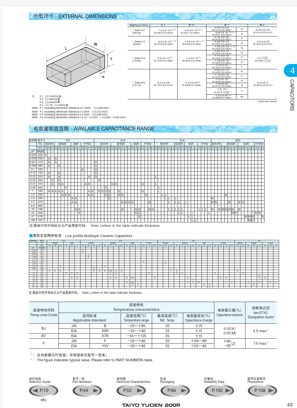
外型尺寸 EXTERNAL DIMENSIONS
CAPACITORS
1. 0.15mm 公差
2. 0.3mm 公差
3. 0.2mm 公差
4. 0.15/ 0.1mm 公差
Note: 1. Inclulding dimension tolerance 0.15mm 0.006 inch .Note: 2. Inclulding dimension tolerance 0.3mm 0.012 inch .Note: 3. Inclulding dimension tolerance 0.2mm 0.008 inch .
Note: 4. Inclulding dimension tolerance 0.15/ 0.1mm 0.006/ 0.004 inch .
电容量取值范围 AVAILABLE CAPACITANCE RANGE
薄型多层陶瓷电容 Low pro? le Multilayer Ceramic Capacitors
? ? ? ?!!
* 此处数据为代表值。详情请参见型号一览表。* The ? gure indicates typical value. Please refer to PART NUMBERS table.
? ? ? ?!!
型号一览 PART NUMBERS
通用·薄型多层陶瓷电容器 General Low pro?
le Multilayer Ceramic Capacitors 107型 107TYPE
**因个别规格约定,将提供X7R规格对应的说明书。 We may provide X7R for some items according to the individual speci?
cation.
温度特性 Temp.char. B7:X7R
Please specify the capacitance tolerance code.
* Test Voltage of Loading at high temperature test is 1.5 time of the rated voltage.
请在型号的 中指定电容量公差代码。*高温负载试验电压为额定电压的1.5倍。
CAPACITORS
温度特性 Temp.char. F:F/Y5V
型号一览 PART NUMBERS
212型 212TYPE
Please specify the capacitance tolerance code.
* Test Voltage of Loading at high temperature test is 1.5 time of the rated voltage.** We may provide X7R for some items according to the individual speci? cation.
请在型号的 中指定电容量公差代码。*高温负载试验电压为额定电压的1.5倍。
**因个别规格约定,将提供X7R 规格对应的说明书。
CAPACITORS
温度特性 Temp.char. B7:X7R
温度特性 Temp.char. F:F/Y5V
Please specify the capacitance tolerance code.
* Test Voltage of Loading at high temperature test is 1.5 time of the rated voltage.请在型号的 中指定电容量公差代码。*高温负载试验电压为额定电压的1.5倍。
Please specify the capacitance tolerance code.
* Test Voltage of Loading at high temperature test is 1.5 time of the rated voltage.
请在型号的 中指定电容量公差代码。*高温负载试验电压为额定电压的1.5倍。
316型 316TYPE
温度特性 Temp.char. B7:X7R
**因个别规格约定,将提供X7R 规格对应的说明书。**We may provide X7R for some items according to the individual speci? cation
CAPACITORS
325型 325TYPE
Please specify the capacitance tolerance code.
* Test Voltage of Loading at high temperature test is 1.5 time of the rated voltage.** We may provide X7R for some items according to the individual speci? cation.
请在型号的 中指定电容量公差代码。*高温负载试验电压为额定电压的1.5倍。
**因个别规格约定,将提供X7R 规格对应的说明书。
Please specify the capacitance tolerance code.
* Test Voltage of Loading at high temperature test is 1.5 time of the rated voltage.
请在型号的 中指定电容量公差代码。*高温负载试验电压为额定电压的1.5
倍。
温度特性 Temp.char. F:F/Y5V
阻抗、ESR 频率特性例 Example of Impedance ESR vs. Frequency characteristics
太阳诱电多层陶瓷电容器例 (Taiyo Yuden multilayer ceramic capacitor)
CAPACITORS
!Taped packaging
带装材质 Taping material
※压模袋型无底胶
WK
WK
分别按105, 107, 212形状接受订货,敬请咨询。
Please contact any of our of? ces for accepting your requirement accord-ing to dimensions 0402, 0603, 0805.(inch)
散装盒 Bulk Cassette
最小订货单位数量 Minimum Quantity
CAPACITORS
编带尺寸 Taping dimensions
压印带 Embossed tape 8mm 宽 0.315inches wide Unit mm inch
引带 空白部分 Leader and Blank portion
卷盘尺寸 Reel size
面胶强度 Top Tape Strength
面胶的剥离力应在0.1 0.7N以内,其方向如下图所示。
The top tape requires a peel-off force of 0.1 0.7N in the direction of the arrow as illustrated below.
多层陶瓷电容器
注2 热处理 多层型 测试之前,应在 150 下进行1小时的热处理,并在标准状况下放置24 2小时。注3 电压处理 多层型 测试之前,应在测试规定温度和电压下进行1小时的电压处理并在标准状况下放置24 2小时。注4 5 本数值为代表值。详情请参照各自规格。注6 有些部件适用额定电压 1.5。详情请参照个别规格书。此处所述“标准状态”为:
温度5 35 相对湿度45 85 气压86 106kPa
对测试结果存有疑义时,则在以下条件下进行测试: 温度20 2 相对湿度60 70 气压86 106kPa 如无特别指定,所有测试全部在“标准状态”下进行。
0 10
多层陶瓷电容器
超级电容基本参数概念 寿命Lifetime 超级电容器具有比二次电池更长的使用寿命,但它的使用寿命并不是无限的,超级电容器基本失效的形式是电容内阻的增加( ESR)与(或) 电容容量的降低.,电容实际的失效形式往往与用户的应用有关,长期过温(温度)过压(电压),或者频繁大电流放电都会导致电容内阻的增加或者容量的减小。在规定的参数范围内使用超级电容器可以有效的延长超级电容器的寿命。通常,超级电容器具有于普通电解电容类似的结构,都是在一个铝壳内密封了液体电解液,若干年以后,电解液会逐渐干涸,这一点与普通电解电容一样,这会导致电容内阻的增加,并使电容彻底失效。 电压Voltage 超级电容器具有一个推荐的工作电压或者最佳工作电压,这个值是根据电容在最高设定温度下最长工作时间来确定的。如果应用电压高于推荐电压,将缩短电容的寿命,如果过压比较长的时间,电容内部的电解液将会分解形成气体,当气体的压力逐渐增强时,电容的安全孔将会破裂或者冲破。短时间的过压对电容而言是可以容忍的。 极性Polarity 超级电容器采用对称电极设计,也就说,他们具有类似的结构。当电容首次装配时,每一个电极都可以被当成正极或者负极,一旦电容被第一次100%从满电时,电容就会变成有极性了,每一个超级电容器的外壳上都有一个负极的标志或者标识。虽然它们可以被短路以使电压降低到零伏,但电极依然保留很少一部分的电荷,此时变换极性是不推荐的。电容按照一个方向被充电的时间越长,它们的极性就变得越强,如果一个电容长时间按照一个方向充电后变换极性,那么电容的寿命将会被缩短。 温度Ambient Temperature 超级电容器的正常操作温度是-40 ℃~70℃,温度与电压的结合是影响超级电容器寿命的重要因素。通常情况下,超级电容器是温度每升高10℃,电容的寿命就将降低30%~50%,也就说,在可能的情况下,尽可以的降低超级电容器的使用温度,以降低电容的衰减与内阻的升高,如果不可能降低使用温度,那么可以降低电压以抵清高温对电容的负面影响。比如,如果电容的工作电压降低为1.8V,那么电容可以工作于65℃高温下。如果在低于室
【 南京南山半导体有限公司 — 贴片电容选型资料】
https://www.doczj.com/doc/4517837235.html,
MULTILAYER CHIP CERAMIC CAPACITOR
COG/COH
COG
, ,
-55
125
,
0
30ppm/
0
60ppm/
0805
CG
101
J
500
N
T
(PF) ( 0402 0.04 0603 0.06 0805 0.08 1206 0.12 ) 0.02 0.03 0.05 0.06 1.00 1.60 2.00 3.20 ( ) 0.50 0.80 1.25 1.60 CG CH COG NPO COH 100 101 102 10 10
0 1
J G C B D
5.00% 2.00% 0.25PF 0.10PF 0.50PF
10 10 10 10
2
6R3 100 250 500
6.3V 10V 25V 50V
S C N / / T B
WB
W
T
L mm L 0402 0603 0805 1206 1005 1608 2012 3216 1.00 1.60 2.00 3.20 0.05 0.10 0.20 0.30 W 0.50 0.80 1.25 1.60 0.05 0.50 0.10 0.80 0.20 0.80 1.00 1.25 0.20 0.80 1.00 1.25 T WB 0.05 0.25 0.10 0.30 0.20 0.50 0.20 0.20 0.20 0.60 0.20 0.20 0.10 0.10 0.20 0.30
15
金风风力机技术参数
技术数据一览表 表1、GW121/2500kW机组主要技术数据编 号 项目技术参数与规格备注1 认证级别IEC IIIB及以下 2 最大风速37.5 m/s 50年一遇(10分钟平均) 3 极大风速52.5 50年一遇(3秒平均) 4 运行环境温度-30℃~+40℃ 5 生存环境温度-40℃~+50℃ 6 相对湿度≤95% 7 防护等级IP54 发电机 8 转子转速7~15.5 rpm 9 叶尖线速度85.8 m/s 10 切入风速 3 m/s 11 额定风速(静 态) 9.3 m/s 12 切出风速(10 分钟均值) 22 m/s
号 项目技术参数与规格备注 13 再启动风速风机切出后,机组持续检测风速小于切出风速(同时满足10分钟平均风速、10s持续风速、3s瞬时风速),机组即可并网。 14 再启动温度-18 ℃ 15 功率调整方式变桨变速调节 16 紧急刹车方式3个叶片顺桨实现气动刹车 17 风速-桨角关系高于额定风速变桨控制 18 风速-转速关系低于额定风速变速控制 19 噪音(整个风电 机组) <103 dB 20 轮毂中心高度90 m 21 叶轮直径121.5 m
号 项目技术参数与规格备注 22 叶片数目 3 23 扫风面积11595 m2 24 风向排列(取 向) 上风向 25 叶轮倾斜度 3 deg 26 叶片锥度-3 deg 27 叶片制造商见报价文件 28 叶片加工工艺真空吸注 29 叶片材料玻璃纤维增强树脂 30 叶片长度59.5 m 31 叶片根部连接 件 螺栓 32 叶片根部到轮 毂中心的距离 1.17 m 33 叶片纵剖面图 34 弦(根/尖)长最大弦长约3 m
Polypropylene (PP) Film and Foil Capacitors for Pulse Applications in PCM 7.5 mm to 15 mm Pulse duty construction Very low dissipation factor Negative capacitance change versus temperature Very low dielectric absorption According to RoHS 2002/95/EC Typical Applications For high frequency applications e.g. Sample and hold Timing LC-Filtering Oscillating circuits Audio equipment Dielectric: Polypropylene (PP) film Capacitor electrodes: Metal foil Internal construction: Encapsulation: Solvent-resistant, flame-retardent plastic case with epoxy resin seal, UL 94 V-0 Terminations: Tinned wire Marking: Colour: Red. Marking: Black. Epoxy resin seal: Yellow. Capacitance range: 100 pF to 0.22 μF (E12-values on request) Rated voltages: 63VDC, 100VDC, 250VDC, 400VDC, 630VDC, 1000VDC Capacitance tolerances: ±20%, ±10%, ±5% Operating temperature range: -55°C to +100°C Test specifications: In accordance with IEC 60384-13 and EN 131800 Climatic test category: 55/100/56 in accordance with IEC Insulation resistance at +20°C: > 5 x 10⁵ M (mean value: 1 x 10⁶ M) Measuring voltage: Ur = 63V: Utest = 50 V/1 min. Ur > 100V: Utest = 100 V/1 min. Dissipation factors at +20°C: tan Test voltage: 2 Ur, 2 sec Maximum pulse rise time: 1000 V/μsec for pulses equal to the rated voltage Dielectric absorption: 0.05% Temperature coefficient: -200 x 10-6/°C (typical) Voltage derating: A voltage derating factor of 1.35% per K must be applied from +85°C for DC voltages and from +75°C for AC voltages. Reliability: Operational life > 300000 hours Failure rate < 5 fit (0.5 x Ur and 40°C) Graphs: Soldering: Mechanical Tests Packing Pull test on leads: 10 N in direction of leads according to IEC 60068-2-21 Vibration: 6 hours at 10...2000Hz and 0.75mm displacement amplitude or 10g in accordance with IEC 60068-2-6 Low air density: Available taped and reeled. Detailed taping information: Example for ordering / Part number:
电池基本参数说明 额定电压:电池正常工作的电压。 额定容量:例如:28Ah(20hr,1.75V/cell,25℃) 是指在25℃时,20小时放电(即2.8A)使单个电池电压降到1.75V所放出的容量,折算到1小时放电的安培值。 尺寸:长、宽、高、总高。 内阻:例如:4.0mΩ(25℃,充满电) CCA:冷启动电流值:在-17.8℃和-28.9℃条件下,充满电的12V蓄电池在30s 内,其端电压下降到7.2V时,蓄电池所能供给的最小电流。 储备容量(25℃):完全充足电的12V蓄电池,在25±2℃的条件下,以25A恒流放电至蓄电池端电压下降到10.5±0.05V时的放电时间。 环境温度:电池工作的温度,有的细分充电温度与放电温度。 DODxx%:电池用掉xx%的电。如:“DOD80%,700次”则说明电池每次都用去80%的电,可循环使用700次。 最大充电电流:例如:4.5C20。是指在以20小时放电为标准的电池容量数值乘以4.5即为最大充电电流。 最大放电电流:算法同上,即为最大的放电电流。 循环充电电压:也有叫浮充电压,是指将蓄电池组与电源线路并联连接到负载电路上,电源线路仅略高于蓄电池组的断路电压,由电源线路所供的少量电流来补偿蓄电池组局部作用的损耗,以使其能经常保持在充电满足状态而不致过充电。电极L或R:有正极、反极电池之分。区分方法: 1、在外包装或者电池上,反极电池一般会标注"L"字样。正极电池一般不标注。 2、面对电池极柱靠近自己一侧,正极电池‘+’极柱在电池左侧,反之在右侧。比能量: 体积能量密度:以wh/L为单位,体现单位体积下电池可以存储的能量大小。 重量能量密度:以wh/kg为单位,体现单位重量下电池可以存储的能量大小。比功率:以kw/kg为单位,体现单位重量下电池可以输出的功率。 电池三段式充电 一、恒流段:当电池电压较低时,为了避免充电电流过大损坏电池,应该限制充电电流不能过大,又为了缩短充电时间,应使用最大允许充电电流充电。恒流充电阶段为主充电阶段,电池已经充入约85~90%的电量。 二、恒压段:保持这个恒定的电压对电池充电,在恒压充电过程中,电池电压会越来越高,电流会越来越小,当充电电流下降到0.5C时,恒压充电结束。 三、浮充段:浮充电阶段实际上也是恒压充电,在这个阶段的充电电压一般控制在13.6~13.8V左右,充电电流较自放电电流略大,一般为0.01~0.03C左右。通过涓流充电,可以将电池电量充到接近100%。 铅蓄电池外壳文字说明 例如:6-QAW-100-D 6:代表串联的电池数,每个2V,即12V
WRITTEN CHECKED APPROVED To. : DATE : 200 . . . SPECIFICATION PRODUCT : STARCAP MODEL : DMS series KORCHIP CORP. KORCHIP B/D, 817-38, Anyang 2-dong, Manan-gu, Anyang-si, Gyeonggi-do, KOREA TEL : 82 - 31 - 361 - 8000 FAX : 82 - 31 - 361 - 8080
Page No.ITEM etc. 1Cover Page 2Index 3 1. Scope 2. Part Number System 3. Product Model Name 4. Photo 5. Nominal Specifications 4 6. Cell Structure 7. Product Construction And Dimension 5 8. Packing Specifications 6 9. Specifications And Test Method 7 10. Measuring Method Of Characteristics 8 11. Mounting And Soldering 9 12. Cautions For Use 10 13. Environmental Management Index
Items DMS 3R3 204 R DMS 3R3 224 R Cell Size ?6.8 × 1.4mm ?6.8 × 1.4mm OPERATING TEMPERATURE -10 ~ +60 ℃-10 ~ +60 ℃RATED VOLTAGE 3.3 VDC 3.3 VDC ELECTROSTATIC CAPACITANCE (F) 0.20 F 0.22 F CAPACITANCE TOLERANCE -20 ~ 80 %-20 ~ 80 %EQUIVALENT SERIES RESISTANCE (ESR)LESS THAN 200?LESS THAN 200?LEAKAGE CURRENT (LC) LESS THAN 150? LESS THAN 150? 1. Scope This specification applies to STARCAP(Electric Double Layer Capacitor), submitted to specified customer in cover page. 2. Part Number System DMS 3R3 204 R (Example) ① ② ③ ④ ① Series Name ② Rated Voltage : 3.3VDC ③ Capacitance : 0.20 F (204 = 20 × 10+4 uF) ④ Terminal Type : R-type 3. Product Model Name 1) Product : Electric Double Layer Capacitor 2) Model name : DMS3R3204R, DMS3R3224R 4. Photo 5. Nominal Specifications
电容器标称电容值 E24 E12 E6 E24 E12 E6 1.0 1.0 1.0 3.3 3.3 3.3 1.1 3.6 1.2 1.2 3.9 3.9 1.3 4.3 1.5 1.5 1.5 4.7 4.7 4.7 1.6 5.1 1.8 1.8 5.6 5.6 2.0 6.2 2.2 2.2 2.2 6.8 6.8 6.8 2.4 7.5 2.7 2.7 8.2 8.2 3.0 9.1 注:用表中数值再乘以10n来表示电容器标称电容量,n为正或负整数。 主要参数的意义:标称容量以及允许偏差:目前我国采用的固定式标称容量系列是:E24,E12,E6系列。他们分别使用的允许 偏差是+-5% +-10% +-20%。 现在较为通用的容值代码表示方法为三位代码“XXY”表示法,前两位数字表示乘系数,后一位表示乘指数,单位为pF。其中一般前两位的取值范围为上述E6和E12系列,后一位数字表示乘指数10 n。当Y= 9时,对应前述n = -1;当Y= 8时,对应前述n = -2;当Y= 0,1,2,3,4,5,6,7时,Y就等于n。 示例如下: 0.5pF容值代码表示为508; 68pF容值代码表示为680; 1 pF容值代码表示为109; 120pF容值代码表示为121; 4.7pF容值代码表示为479; 2200pF容值代码表示为222;10pF容值代码表示为100; 100000pF容值代码表示为104(0.1μF); 47μF容值代码表示为476; 330μF容值代码表示为337 //-------------------------------------------------- 【单位pF】 39 P 43 P 47 P 51 P 56 P 62 P 68 P 75 P 82 P 91 P 100 P 120 P 150 P 180 P 200 P 220 P 240 P 270 P 300 P 330 P 360 P 390 P
1. Scope This specification is applies to Multilayer Ceramic Chip Capacitor(MLCC) for use in electric equipment for the voltage is ranging from 4V to 50V. The series suitable for general electrics circuit, telecommunications, personal computers and peripheral, power circuit and mobile application. (This product compliant with the RoHS.) 2. Parts Number Code (6)Rated Voltage Code Rated Voltage (Vdc) 004 4 007 6.3 010 10 016 16 025 25 035 35 050 50 (1) (2) (3) (4) (5) (6) (7) (1)Product Product Code C Multilayer Ceramic Chip Capacitor (3)Temperature Characteristics Code Temperature Characteristic Temperature Range Temperature Coefficient N NPO -55℃~+125℃ 30 ppm/℃ X X7R -55℃~+125℃ ± 15% B X5R -55℃~+85℃ ± 15% R X7S -55℃~+125℃ ± 22% S X6S -55℃~+105℃ ± 22% Y Y5V -30℃~+85℃ +22/-82% Z Z5U +10℃~+85℃ +22/-56% E Y5U -30℃~+85℃ +22/-56% (4)Capacitance unit :pico farads(pF) Code Nominal Capacitance (pF) 5R0 5.0 120 12.0 151 150.0 222 2,200.0 473 47,000.0 224 220,000.0 105 1,000,000.0 106 10,000,000.0 ※. If there is a decimal point, it shall be expressed by an English capital letter R (5)Capacitance Tolerance Code Tolerance Nominal Capacitance B ± 0.10 pF C ± 0.25 pF D ± 0.50 pF F ± 1.00 pF Less Than 10 pF (Include 10 pF) F ± 1.00 % G ± 2.00 % J ± 5.00 % K ± 10.0 % M ± 20.0 % Z +80/-20 % More Than 10 pF (7)Tapping Code Type (2)Chip Size Code Length×Width unit : mm(inch) 0201 0.60× 0.30 (.024× .011) 0402 1.00× 0.50 (.039× .020) 0603 1.60× 0.80 (.063× .031) 0805 2.00× 1.25 (.079× .049) 1206 3.20× 1.60 (.126× .063) 1210 3.20× 2.50 (.126× .098) 1808 4.60× 2.00 (.181× .079) 1812 4.60× 3.20 (.181× .125) 1825 4.60× 6.35 (.181× .250) 2208 5.70× 2.00 (.220× .197) 2211 5.70× 2.80 (.220× .110) 2220 5.70× 5.00 (.220× .197) 2225 5.70× 6.35 (.220× .250)
一、特性 III类瓷,也叫做半导体型(Semiconductor Type ),是一种具有半导体特徵的陶瓷电容器。该类电容器适用於作旁路和耦合之用。该类陶瓷介质是以在类别温度范围内电容量非线性变化来表徵。 其特性符合GB 11305 - 89 标准的要求。 用途:(1). 晶体管化的电路;(2). 低压电路的旁路耦合;(3). 对损耗、绝缘电阻及容量稳定性要求一般的鉴定电路。 二、温度系数、额定电压、静电容量关系表: 温度特性Y5P Y5V Y5U Y5R 额定电压(VDC) 10-50 10-16 25 50 10-50 10-50 标称容量 范围332-104 103-474 103-334 103-224 103-224 102-104 测试条件 1 K Hz±20%, 0.1 Vrms + 0.2Vrms at 25± 1℃ 容量误差± 10% ± 20% +80/-20% ± 20% ± 10% 使用温度范围-25~+ 85 ℃ 损耗正切值(%) 5.0 max 绝缘电阻U R<25VDC:200MΩ 或10ΩF 取小者,U R (U R≤16VDC测试电压为16V DC ) 充电60S U R=25VD:500MΩ 或10ΩF 取小者,U R充电60S U R>25VDC:1000MΩ 或20ΩF 取小者,U R充电60S 耐电压测试 1 .5U R 尺寸说明: 1. 上图为标准引线长度、形式图形,但也可根据客户要求进行生产。 2. C 尺寸要求为:1.5mm 最大。 3. D 与T 尺寸根据标称容量与额定电压大小决定,一般来说:同材质情况 下,容量越大,D 尺寸越大;额定电压越高,T 尺寸越厚。 4. 可根据客户要求生产散件与适合A/I 自动插件的编带( 带装) 产品。
CD11型产品规格书CD11 Series Product Specification 一、适用范围 Adapt Range 本产品规格书适用于chang 牌CD11型铝电解电容器产品。 ±20% (120Hz, +20℃) 漏电流 Leakage current For capacitance value >1000μF, add 0.02 per another 1000μF U R (V) 6.3 10 16 25 35 50 63 100 Z-25℃/Z+20℃ 5 4 3 2 2 2 2 2 Z-40℃/Z+20℃ 12 10 8 5 4 3 3 3 U R (V) 160 200 250 400 450 Z-25℃/Z+20℃ 3 3 4 8 10 Z-25℃/Z+20℃,容量大于1000μF 者,每增加1000μF 阻抗比增加0.5 For capacitance value > 1000μF,Add 0.5 per another 1000μF for Z-25°C/ Z+20℃ Z-40℃/Z+20℃,容量大于1000μF 者,每增加1000μF 阻抗比增加1.0 For capacitance value >10000-40℃/ Z+20℃
续上表
六、标称电容量、额定电压、浪涌电压与外形尺寸对应表 Nominal capacitance, rated voltage, surge voltage and case size table.
六、标志 Marking 七、铝电解电容器的使用注意事项 Guidelines For Using Aluminum Electrolytic Capacitor 为使您获得电解电容器的最佳性能和延长电解电容器的使用寿命,在使用电解电容器器前,请务必阅读本注意事项。 Upon using Aluminum Electrolytic Capacitors ,please proper handing and observing to following important points will insure optimum capacitor performance and long life. 1、直流电解电容器是有极性的 DC electrolytic capacitors are polarized. ① ② ③
产品技术规格书 文件编号 产品名称多层陶瓷电容技术规格书 产品型号 产品图号
目录 1 目的和适用范围 2 1.1目的 2 1.2适用范围 2 2 引用和参考的相关标准 2 3 功能简述 3 4 要求 3 4.1一般要求 3 4.2电气要求 4 4.3环境试验要求 4 4.4安全要求测试10 4.5 包装、运输、贮存10 4.6质量与可靠性10 4.7 加工工艺说明10 5对供应商的要求11 5.1规范接收11 5.2提供资料和数据11 5.3产品更改通知(PCN)11 5.4质量控制要求11 5.5供应商承诺11 6资格认证11 6.1样本11 6.2样本试验11 6.3 资格认证试验12 7重要说明12 ------------------------------------------------------------------------------------------------------------------------------------------------------------ - Copyright ? 2006Xinwei Technologies Co. Ltd., All Rights Reserved
1.1 目的 物料技术规格书是描述公司外购或外协物料的受控性文件,是公司物料规范化管理的基石。其作用为: ·供应厂商进行产品设计、生产和检验的依据 ·质量部门验货、退货的依据 ·采购部进行采购的依据 ·对供应厂商产品质量进行技术认证的依据 ·研发部门选用物料的依据 本技术规格书的目的是让供应厂商了解信威通信公司对该物料在质量及其可靠性方面的要求,只有质量和可靠性两方面都100%达到要求的物料才被信威通信公司接受。信威通信公司有权取消不合格产品供应商的资格,有权在必要时修改本技术规范的有关内容,届时供应商会提前收到有关更改通知并给予适当的时间来做相应的更改。 1.2 适用范围 本规格书适用于供应厂商进行多层陶瓷电容器设计、生产以及检验,指导质量部对供应厂商提供的多层陶瓷电容器进行技术认证及进货检验,指导采购部采购合格产品,研发部在设计新产品时选用合格物料。 2引用和参考的相关标准 GB/T 2423.1-2001 电工电子产品环境试验第2部分:试验方法试验A:低温 GB/T 2423.2-2002 电工电子产品环境试验第2部分: 试验方法试验B: 高温 GB/T 2423.3-1993 电工电子产品基本环境试验规程试验Ca:恒定湿热试验方法 GB/T 2423.10-1995 电工电子产品环境试验第2部分:试验方法试验Fc和导则:振动 GB/T 3873-1983 通信设备产品包装通用技术条件 GB/T 2828.1-2003 计数抽样检验程序第1部分:按接收质量限(AQL)检索的逐批检验抽样计划 GB/T 2693-2001 电子设备用固定电容器第1部分:总规范 GB/T 5968-1996 电子设备用固定电容器第9部分:分规范2类瓷介固定电容器 ------------------------------------------------------------------------------------------------------------------------------------------------------------- Copyright ? 2006Xinwei Technologies Co. Ltd., All Rights Reserved
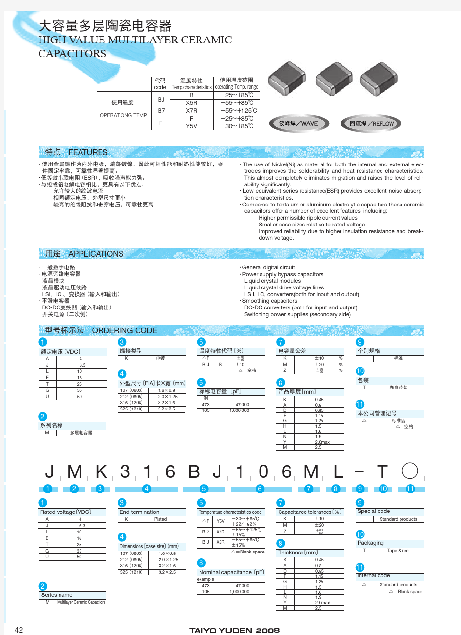
特点 FEATURES 型号标示法 ORDERING CODE 用途 APPLICATIONS G G 使用金属镍作为内外电极,端部镀镍,因此可焊性能和耐热性能较好,器 件固定牢靠,可靠性显著提高。 低等效串联电阻 ESR ,吸收噪声能力强。 与钽或铝电解电容相比,更具有以下优点: 允许较大的纹波电流 相同额定电压,外型尺寸更小 较高的绝缘阻抗和击穿电压,可靠性更高 The use of Nickel(Ni) as material for both the internal and external elec-trodes improves the solderability and heat resistance characteristics. This almost completely eliminates migration and raises the level of reli-ability signi? cantly. Low equivalent series resistance(ESR) provides excellent noise absorp-tion characteristics. Compared to tantalum or aluminum electrolytic capacitors these ceramic capacitors offer a number of excellent features, including: Higher permissible ripple current values Smaller case sizes relative to rated voltage Improved reliability due to higher insulation resistance and break-down voltage. General digital circuit Power supply bypass capacitors Liquid crystal modules Liquid crystal drive voltage lines LS I, I C, converters(both for input and output) Smoothing capacitors DC-DC converters (both for input and output)Switching power supplies (secondary side) 一般数字电路 电源旁路电容器液晶模块 液晶驱动电压线路LSI IC 变换器 输入和输出 平滑电容器DC-DC 变换器 输入和输出 开关电源 二次侧 大容量多层陶瓷电容器 HIGH V ALUE MULTILAYER CERAMIC CAPACITORS G
Issue date: Mar 2015 Type: C1005 [EIA CC0402] C1608 [EIA CC0603] C2012 [EIA CC0805] C3216 [EIA CC1206] C3225 [EIA CC1210] C4532 [EIA CC1812] C5750 [EIA CC2220] C Series Commercial Grade Mid Voltage (100 to 630V) MULTILAYER CERAMIC CHIP CAPACITORS
SAFETY REMINDERS REMINDERS Please read before using this product Notice: E ffective January 2013, TDK will use a new catalog number which adds product thickness and packaging speci ? cation detail. This new catalog number should be referenced on all catalog orders going forward, and is not applicable for OEM part number orders. Please be aware the last ? ve digits of the catalog number will differ from the item description (internal control number) on the product label. Contact your local TDK Sales representative for more information.(Example) Catalog Issued date Catalog Number Item Description (On Delivery Label)Prior to January 2013C1608C0G1E103J C1608C0G1E103JT000N January 2013 and Later C1608C0G1E103J080AA C1608C0G1E103JT000N 1. If you intend to use a product listed in this catalog for a purpose that may cause loss of life or other damage, you must contact our company’s sales window. 2. We may modify products or discontinue production of a product listed in this catalog without prior noti ? cation. 3. We provide “Delivery Speci ? cation” that explain precautions for the speci ? cations and safety of each product listed in this catalog. We strongly recommend that you exchange these delivery speci ? cations with customers that use one of these products. 4. If you plan to export a product listed in this catalog, keep in mind that it may be a restricted item according to the “Foreign Exchange and Foreign Trade Control Law”. In such cases, it is necessary to acquire export permission in harmony with this law. 5. Any reproduction or transferring of the contents of this catalog is prohibited without prior permission from our company. 6. We are not responsible for problems that occur related to the intellectual property rights or other rights of our company or a third party when you use a product listed in this catalog. We do not grant license of these rights. 7. This catalog only applies to products purchased through our company or one of our company’s of ? cial agencies. This catalog does not apply to products that are purchased through other third parties. REMINDERS
电容器规格型号的标注 1 引言 电容器的型号和规格一般应按国家有关标准来标注。根据目前市场供应情况也有按国外型号标注的,在标注顺序上略有不同。本公司按下述方法标注。 2 电容器规格型号的标注 2.1 标注顺序 电容器一般按下述顺序标注 “型号 -(尺寸代号)-(温度系数或特性)- 额定电压 - 标称容量 - 允许偏差 -(其他)” 其中有些项可能省略。 国外电容器的标注顺序各不相同,例如额定电压在允许偏差后面。 2.2型号 国产电容器的型号命名按“GB/T 2470-1995 电子设备用固定电阻器、固定电容器型号命名方法”规定。例如 ——CC4表示1类多层(独石)瓷介电容器 ——CT4表示2类多层(独石)瓷介电容器 ——CC41表示片状1类多层(独石)瓷介电容器 ——CT41表示片状2类多层(独石)瓷介电容器 ——CA45表示片状固体钽电解电容器 电容器的具体型号和技术参数可参考有关手册。 注意,不同厂家生产的同型号电容器在尺寸和性能指标略有差别。若有影响,需加限制条件。 市场上有国外型号的电容器,若要选用需说明其所属的国家和厂家。 2.3 尺寸代号 片状电容器的尺寸代号常用“0603”、“0805”、“1206”等表示,这是按英寸(0.01in)计的表示法,片状瓷介电容器用此法表示。 还有用EIA代码如“2012”、“3216”等表示,这是按毫米(0.1mm)计的表示法,片状钽电解电容器用此法表示。绘制印制板图时应注意它们尺寸的区别。 带引出线的电容器的尺寸代号不同的厂家不统一,不好标注。一种办法是按生产厂手册标注,但必须同时注明生产厂。另一种办法是不标注尺寸代号,适用于对外型尺寸无严格要求场合,若有要求可以在“其他”项标注对外形尺寸的限制要求,例如限高、限引线间距等。
【MC Series 】 Multilayer Ceramic Chip Capacitor ■Features -Wide capacitance range, extremely compost size -Low inductance of capacitor for high frequency application -Excellent solderability and resistance to soldering heat, suitable for flow and reflow soldering -Adaptable to high-speed surface mount assembly -Conform to EIAJ-RC3402, and also compatible with EIA-RS198 and IEC PUB. 384-10 .. ■Construction ■Dimensions MC / MCHL / MCRF Type Unit: mm Packaging (7” Reel) Type Size (Inch) L W T / Symbol M B Paper tape Plastic tape 01 0201 0.6±0.03 0.3±0.03 0.3±0.03 L 0.15±0.05 15K - 02 0402 1.00±0.05 0.50±0.05 0.50±0.05 N 0.25 +0.05 / -0.10 10K - 1.60±0.10 0.80±0.10 0.80±010 S 4K 03 0603 1.60 +0.15 / -0.10 0.80 +0.15 / -0.10 0.80 +0.15 / -0.10 X 0.40±0.15 4K - 0.60±0.15 A 4K - 0.80±0.10 B 4K - 2.00±0.15 1.25±0.10 D - 3K 0.85±0.10 T 4K - 05 0805 2.00±0.20 1.25±0.20 1.25±0.20 I 0.50±0.20 - 3K 0.80±0.10 B 4K - 0.95±0.10 C - 3K 3.20±0.15 1.25±0.10 D - 3K 1.60±0.15 1.15±0.15 J - 3K 3.20±0.20 1.60±0.20 1.60±0.20 G - 2K 06 1206 3.20+0.3 / -0.1 1.60+0.3 / -0.1 1.60+0.3 / -0.1 P 0.60±0.20 (0.50±0.20)*** - 2K 0.95±0.10 C - 3K 3.20±0.30 2.50±0.20 1.25±0.10 D - 3K 1.60±0.20 G - 2K 2.00±0.20 K - 1K 10 1210 3.20±0.40 2.50±0.30 2.50±0.30 M 0.75±0.25 - 1K 1.25±0.10 D - 2K 08 1808 4.50±0.40 (4.5+0.5/-0.3)** 2.03±0.25 2.00±0.20 K 0.75±0.25 (0.50±0.20)*** - 1K 1.25±0.10 D - 1K 3.20±0.30 2.00±0.20 K - 1K 12 1812 4.50±0.40 (4.5+0.5/-0.3)** 3.20±0.40 2.50±0.30 M 0.75±0.25 (0.50±0.20)*** - 0.5K ** For 1808/1812: 200~3KV , ***For 1206:1KV~3KV ; 1808/1812: 200~3KV Low Inductance Capacitors for MCLI Type Unit: mm Packaging (7” Reel) Type Size (Inch) L W T / Symbol Ta min. Tb min. Paper tape Plastic tape MCLI43 0612 3.20±0.15 1.60±0.15 0.80±0.10 B 0.5 0.13 4K - 1Ceramic Material 3 Termination: 2 Inner Electrodes NPO: Ag/Ni/Sn dielectric X7R, Y5V, X5R: Cu/Ni/Sn dielectric 1 2 3