机械专业毕业设计外文翻译--工艺规程制订
- 格式:docx
- 大小:25.36 KB
- 文档页数:9
毕业论文中英文资料外文翻译文献附录附录1:英文原文Selection of optimum tool geometry and cutting conditionsusing a surface roughness prediction model for end milling Abstract Influence of tool geometry on the quality of surface produced is well known and hence any attempt to assess the performance of end milling should include the tool geometry. In the present work, experimental studies have been conducted to see the effect of tool geometry (radial rake angle and nose radius) and cutting conditions (cutting speed and feed rate) on the machining performance during end milling of medium carbon steel. The first and second order mathematical models, in terms of machining parameters, were developed for surface roughness prediction using response surface methodology (RSM) on the basis of experimental results. The model selected for optimization has been validated with the Chi square test. The significance of these parameters on surface roughness has been established with analysis of variance. An attempt has also been made to optimize the surface roughness prediction model using genetic algorithms (GA). The GA program gives minimum values of surface roughness and their respective optimal conditions.1 IntroductionEnd milling is one of the most commonly used metal removal operations in industry because of its ability to remove material faster giving reasonably good surface quality. It is used in a variety of manufacturing industries including aerospace and automotive sectors, where quality is an important factor in the production of slots, pockets, precision moulds and dies. Greater attention is given to dimensional accuracy and surface roughness of products by the industry these days. Moreover, surface finish influences mechanical properties such as fatigue behaviour, wear, corrosion, lubrication and electrical conductivity. Thus, measuring and characterizing surface finish can be considered for predicting machining performance.Surface finish resulting from turning operations has traditionally received considerable research attention, where as that of machining processes using multipoint cutters, requires attention by researchers. As these processes involve large number of parameters, it would bedifficult to correlate surface finish with other parameters just by conducting experiments. Modelling helps to understand this kind of process better. Though some amount of work has been carried out to develop surface finish prediction models in the past, the effect of tool geometry has received little attention. However, the radial rake angle has a major affect on the power consumption apart from tangential and radial forces. It also influences chip curling and modifies chip flow direction. In addition to this, researchers [1] have also observed that the nose radius plays a significant role in affecting the surface finish. Therefore the development of a good model should involve the radial rake angle and nose radius along with other relevant factors.Establishment of efficient machining parameters has been a problem that has confronted manufacturing industries for nearly a century, and is still the subject of many studies. Obtaining optimum machining parameters is of great concern in manufacturing industries, where the economy of machining operation plays a key role in the competitive market. In material removal processes, an improper selection of cutting conditions cause surfaces with high roughness and dimensional errors, and it is even possible that dynamic phenomena due to auto excited vibrations may set in [2]. In view of the significant role that the milling operation plays in today’s manufacturing world, there is a need to optimize the machining parameters for this operation. So, an effort has been made in this paper to see the influence of tool geometry(radial rake angle and nose radius) and cutting conditions(cutting speed and feed rate) on the surface finish produced during end milling of medium carbon steel. The experimental results of this work will be used to relate cutting speed, feed rate, radial rake angle and nose radius with the machining response i.e. surface roughness by modelling. The mathematical models thus developed are further utilized to find the optimum process parameters using genetic algorithms.2 ReviewProcess modelling and optimization are two important issues in manufacturing. The manufacturing processes are characterized by a multiplicity of dynamically interacting process variables. Surface finish has been an important factor of machining in predicting performance of any machining operation. In order to develop and optimize a surface roughness model, it is essential to understand the current status of work in this area.Davis et al. [3] have investigated the cutting performance of five end mills having various helix angles. Cutting tests were performed on aluminium alloy L 65 for three milling processes (face, slot and side), in which cutting force, surface roughness and concavity of a machined plane surface were measured. The central composite design was used to decide on the number of experiments to be conducted. The cutting performance of the end mills was assessed usingvariance analysis. The affects of spindle speed, depth of cut and feed rate on the cutting force and surface roughness were studied. The investigation showed that end mills with left hand helix angles are generally less cost effective than those with right hand helix angles. There is no significant difference between up milling and down milling with regard tothe cutting force, although the difference between them regarding the surface roughness was large. Bayoumi et al.[4] have studied the affect of the tool rotation angle, feed rate and cutting speed on the mechanistic process parameters (pressure, friction parameter) for end milling operation with three commercially available workpiece materials, 11 L 17 free machining steel, 62- 35-3 free machining brass and 2024 aluminium using a single fluted HSS milling cutter. It has been found that pressure and friction act on the chip – tool interface decrease with the increase of feed rate and with the decrease of the flow angle, while the cutting speed has a negligible effect on some of the material dependent parameters. Process parameters are summarized into empirical equations as functions of feed rate and tool rotation angle for each work material. However, researchers have not taken into account the effects of cutting conditions and tool geometry simultaneously; besides these studies have not considered the optimization of the cutting process.As end milling is a process which involves a large number f parameters, combined influence of the significant parameters an only be obtained by modelling. Mansour and Abdallaet al. [5] have developed a surface roughness model for the end milling of EN32M (a semi-free cutting carbon case hardening steel with improved merchantability). The mathematical model has been developed in terms of cutting speed, feed rate and axial depth of cut. The affect of these parameters on the surface roughness has been carried out using response surface methodology (RSM). A first order equation covering the speed range of 30–35 m/min and a second order equation covering the speed range of 24–38 m/min were developed under dry machining conditions. Alauddin et al. [6] developed a surface roughness model using RSM for the end milling of 190 BHN steel. First and second order models were constructed along with contour graphs for the selection of the proper combination of cutting speed and feed to increase the metal removal rate without sacrificing surface quality. Hasmi et al. [7] also used the RSM model for assessing the influence of the workpiece material on the surface roughness of the machined surfaces. The model was developed for milling operation by conducting experiments on steel specimens. The expression shows, the relationship between the surface roughness and the various parameters; namely, the cutting speed, feed and depth of cut. The above models have not considered the affect of tool geometry on surface roughness.Since the turn of the century quite a large number of attempts have been made to find optimum values of machining parameters. Uses of many methods have been reported in the literature to solve optimization problems for machining parameters. Jain and Jain [8] have usedneural networks for modeling and optimizing the machining conditions. The results have been validated by comparing the optimized machining conditions obtained using genetic algorithms. Suresh et al. [9] have developed a surface roughness prediction model for turning mild steel using a response surface methodology to produce the factor affects of the individual process parameters. They have also optimized the turning process using the surface roughness prediction model as the objective function. Considering the above, an attempt has been made in this work to develop a surface roughness model with tool geometry and cutting conditions on the basis of experimental results and then optimize it for the selection of these parameters within the given constraints in the end milling operation.3 MethodologyIn this work, mathematical models have been developed using experimental results with the help of response surface methodolog y. The purpose of developing mathematical models relating the machining responses and their factors is to facilitate the optimization of the machining process. This mathematical model has been used as an objective function and the optimization was carried out with the help of genetic algorithms.3.1 Mathematical formulationResponse surface methodology(RSM) is a combination of mathematical and statistical techniques useful for modelling and analyzing the problems in which several independent variables influence a dependent variable or response. The mathematical models commonly used are represented by:where Y is the machining response, ϕ is the response function and S, f , α, r are milling variables and ∈is the error which is normally distributed about the observed response Y with zero mean.The relationship between surface roughness and other independent variables can be represented as follows,where C is a constant and a, b, c and d are exponents.To facilitate the determination of constants and exponents, this mathematical model will have to be linearized by performing a logarithmic transformation as follows:The constants and exponents C, a, b, c and d can be determined by the method of least squares. The first order linear model, developed from the above functional relationship using least squares method, can be represented as follows:where Y1 is the estimated response based on the first-order equation, Y is the measured surface roughness on a logarithmic scale, x0 = 1 (dummy variable), x1, x2, x3 and x4 are logarithmic transformations of cutting speed, feed rate, radial rake angle and nose radiusrespectively, ∈is the experimental error and b values are the estimates of corresponding parameters.The general second order polynomial response is as given below:where Y2 is the estimated response based on the second order equation. The parameters, i.e. b0, b1, b2, b3, b4, b12, b23, b14, etc. are to be estimated by the method of least squares. Validity of the selected model used for optimizing the process parameters has been tested with the help of statistical tests, such as F-test, chi square test, etc. [10].3.2 Optimization using genetic algorithmsMost of the researchers have used traditional optimization techniques for solving machining problems. The traditional methods of optimization and search do not fare well over a broad spectrum of problem domains. Traditional techniques are not efficient when the practical search space is too large. These algorithms are not robust. They are inclined to obtain a local optimal solution. Numerous constraints and number of passes make the machining optimization problem more complicated. So, it was decided to employ genetic algorithms as an optimization technique. GA come under the class of non-traditional search and optimization techniques. GA are different from traditional optimization techniques in the following ways:1.GA work with a coding of the parameter set, not the parameter themselves.2.GA search from a population of points and not a single point.3.GA use information of fitness function, not derivatives or other auxiliary knowledge.4.GA use probabilistic transition rules not deterministic rules.5.It is very likely that the expected GA solution will be the global solution.Genetic algorithms (GA) form a class of adaptive heuristics based on principles derived from the dynamics of natural population genetics. The searching process simulates the natural evaluation of biological creatures and turns out to be an intelligent exploitation of a random search. The mechanics of a GA is simple, involving copying of binary strings. Simplicity of operation and computational efficiency are the two main attractions of the genetic algorithmic approach. The computations are carried out in three stages to get a result in one generation or iteration. The three stages are reproduction, crossover and mutation.In order to use GA to solve any problem, the variable is typically encoded into a string (binary coding) or chromosome structure which represents a possible solution to the given problem. GA begin with a population of strings (individuals) created at random. The fitness of each individual string is evaluated with respect to the given objective function. Then this initial population is operated on by three main operators – reproduction cross over and mutation– to create, hopefully, a better population. Highly fit individuals or solutions are given theopportunity to reproduce by exchanging pieces of their genetic information, in the crossover procedure, with other highly fit individuals. This produces new “offspring” solutions, which share some characteristics taken from both the parents. Mutation is often applied after crossover by altering some genes (i.e. bits) in the offspring. The offspring can either replace the whole population (generational approach) or replace less fit individuals (steady state approach). This new population is further evaluated and tested for some termination criteria. The reproduction-cross over mutation- evaluation cycle is repeated until the termination criteria are met.4 Experimental detailsFor developing models on the basis of experimental data, careful planning of experimentation is essential. The factors considered for experimentation and analysis were cutting speed, feed rate, radial rake angle and nose radius.4.1 Experimental designThe design of experimentation has a major affect on the number of experiments needed. Therefore it is essential to have a well designed set of experiments. The range of values of each factor was set at three different levels, namely low, medium and high as shown in Table 1. Based on this, a total number of 81 experiments (full factorial design), each having a combination of different levels of factors, as shown in Table 2, were carried out.The variables were coded by taking into account the capacity and limiting cutting conditions of the milling machine. The coded values of variables, to be used in Eqs. 3 and 4, were obtained from the following transforming equations:where x1 is the coded value of cutting speed (S), x2 is the coded value of the feed rate ( f ), x3 is the coded value of radial rake angle(α) and x4 is the coded value of nose radius (r).4.2 ExperimentationA high precision ‘Rambaudi Rammatic 500’ CNC milling machine, with a vertical milling head, was used for experimentation. The control system is a CNC FIDIA-12 compact. The cutting tools, used for the experimentation, were solid coated carbide end mill cutters of different radial rake angles and nose radii (WIDIA: DIA20 X FL38 X OAL 102 MM). The tools are coated with TiAlN coating. The hardness, density and transverse rupture strength are 1570 HV 30, 14.5 gm/cm3 and 3800 N/mm2 respectively.AISI 1045 steel specimens of 100×75 mm and 20 mm thickness were used in the present study. All the specimens were annealed, by holding them at 850 ◦C for one hour and then cooling them in a furnace. The chemical analysis of specimens is presented in Table 3. Thehardness of the workpiece material is 170 BHN. All the experiments were carried out at a constant axial depth of cut of 20 mm and a radial depth of cut of 1 mm. The surface roughness (response) was measured with Talysurf-6 at a 0.8 mm cut-off value. An average of four measurements was used as a response value.5 Results and discussionThe influences of cutting speed, feed rate, radial rake angle and nose radius have been assessed by conducting experiments. The variation of machining response with respect to the variables was shown graphically in Fig. 1. It is seen from these figures that of the four dependent parameters, radial rake angle has definite influence on the roughness of the surface machined using an end mill cutter. It is felt that the prominent influence of radial rake angle on the surface generation could be due to the fact that any change in the radial rake angle changes the sharpness of the cutting edge on the periphery, i.e changes the contact length between the chip and workpiece surface. Also it is evident from the plots that as the radial rake angle changes from 4◦to 16◦, the surface roughness decreases and then increases. Therefore, it may be concluded here that the radial rake angle in the range of 4◦to 10◦would give a better surface finish. Figure 1 also shows that the surface roughness decreases first and then increases with the increase in the nose radius. This shows that there is a scope for finding the optimum value of the radial rake angle and nose radius for obtaining the best possible quality of the surface. It was also found that the surface roughness decreases with an increase in cutting speed and increases as feed rate increases. It could also be observed that the surface roughness was a minimum at the 250 m/min speed, 200 mm/min feed rate, 10◦radial rake angle and 0.8 mm nose radius. In order to understand the process better, the experimental results can be used to develop mathematical models using RSM. In this work, a commercially available mathematical software package (MATLAB) was used for the computation of the regression of constants and exponents.5.1 The roughness modelUsing experimental results, empirical equations have been obtained to estimate surface roughness with the significant parameters considered for the experimentation i.e. cutting speed, feed rate, radial rake angle and nose radius. The first order model obtained from the above functional relationship using the RSM method is as follows:The transformed equation of surface roughness prediction is as follows:Equation 10 is derived from Eq. 9 by substituting the coded values of x1, x2, x3 and x4 in termsof ln s, ln f , lnαand ln r. The analysis of the variance (ANOV A) and the F-ratio test have been performed to justify the accuracy of the fit for the mathematical model. Since the calculated values of the F-ratio are less than the standard values of the F-ratio for surface roughness as shown in Table 4, the model is adequate at 99% confidence level to represent the relationship between the machining response and the considered machining parameters of the end milling process.The multiple regression coefficient of the first order model was found to be 0.5839. This shows that the first order model can explain the variation in surface roughness to the extent of 58.39%. As the first order model has low predictability, the second order model has been developed to see whether it can represent better or not.The second order surface roughness model thus developed is as given below:where Y2 is the estimated response of the surface roughness on a logarithmic scale, x1, x2, x3 and x4 are the logarithmic transformation of speed, feed, radial rake angle and nose radius. The data of analysis of variance for the second order surface roughness model is shown in Table 5.Since F cal is greater than F0.01, there is a definite relationship between the response variable and independent variable at 99% confidence level. The multiple regression coefficient of the second order model was found to be 0.9596. On the basis of the multiple regression coefficient (R2), it can be concluded that the second order model was adequate to represent this process. Hence the second order model was considered as an objective function for optimization using genetic algorithms. This second order model was also validated using the chi square test. The calculated chi square value of the model was 0.1493 and them tabulated value at χ2 0.005 is 52.34, as shown in Table 6, which indicates that 99.5% of the variability in surface roughness was explained by this model.Using the second order model, the surface roughness of the components produced by end milling can be estimated with reasonable accuracy. This model would be optimized using genetic algorithms (GA).5.2 The optimization of end millingOptimization of machining parameters not only increases the utility for machining economics, but also the product quality toa great extent. In this context an effort has been made to estimate the optimum tool geometry and machining conditions to produce the best possible surface quality within the constraints.The constrained optimization problem is stated as follows: Minimize Ra using the model given here:where xil and xiu are the upper and lower bounds of process variables xi and x1, x2, x3, x4 are logarithmic transformation of cutting speed, feed, radial rake angle and nose radius.The GA code was developed using MATLAB. This approach makes a binary coding system to represent the variables cutting speed (S), feed rate ( f ), radial rake angle (α) and nose radius (r), i.e. each of these variables is represented by a ten bit binary equivalent, limiting the total string length to 40. It is known as a chromosome. The variables are represented as genes (substrings) in the chromosome. The randomly generated 20 such chromosomes (population size is 20), fulfilling the constraints on the variables, are taken in each generation. The first generation is called the initial population. Once the coding of the variables has been done, then the actual decoded values for the variables are estimated using the following formula: where xi is the actual decoded value of the cutting speed, feed rate, radial rake angle and nose radius, x(L) i is the lower limit and x(U) i is the upper limit and li is the substring length, which is equal to ten in this case.Using the present generation of 20 chromosomes, fitness values are calculated by the following transformation:where f(x) is the fitness function and Ra is the objective function.Out of these 20 fitness values, four are chosen using the roulette-wheel selection scheme. The chromosomes corresponding to these four fitness values are taken as parents. Then the crossover and mutation reproduction methods are applied to generate 20 new chromosomes for the next generation. This processof generating the new population from the old population is called one generation. Many such generations are run till the maximum number of generations is met or the average of four selected fitness values in each generation becomes steady. This ensures that the optimization of all the variables (cutting speed, feed rate, radial rake angle and nose radius) is carried out simultaneously. The final statistics are displayed at the end of all iterations. In order to optimize the present problem using GA, the following parameters have been selected to obtain the best possible solution with the least computational effort: Table 7 shows some of the minimum values of the surface roughness predicted by the GA program with respect to input machining ranges, and Table 8 shows the optimum machining conditions for the corresponding minimum values of the surface roughness shown in Table 7. The MRR given in Table 8 was calculated bywhere f is the table feed (mm/min), aa is the axial depth of cut (20 mm) and ar is the radial depth of cut (1 mm).It can be concluded from the optimization results of the GA program that it is possible toselect a combination of cutting speed, feed rate, radial rake angle and nose radius for achieving the best possible surface finish giving a reasonably good material removal rate. This GA program provides optimum machining conditions for the corresponding given minimum values of the surface roughness. The application of the genetic algorithmic approach to obtain optimal machining conditions will be quite useful at the computer aided process planning (CAPP) stage in the production of high quality goods with tight tolerances by a variety of machining operations, and in the adaptive control of automated machine tools. With the known boundaries of surface roughness and machining conditions, machining could be performed with a relatively high rate of success with the selected machining conditions.6 ConclusionsThe investigations of this study indicate that the parameters cutting speed, feed, radial rake angle and nose radius are the primary actors influencing the surface roughness of medium carbon steel uring end milling. The approach presented in this paper provides n impetus to develop analytical models, based on experimental results for obtaining a surface roughness model using the response surface methodology. By incorporating the cutter geometry in the model, the validity of the model has been enhanced. The optimization of this model using genetic algorithms has resulted in a fairly useful method of obtaining machining parameters in order to obtain the best possible surface quality.中文翻译选择最佳工具,几何形状和切削条件利用表面粗糙度预测模型端铣摘要:刀具几何形状对工件表面质量产生的影响是人所共知的,因此,任何成型面端铣设计应包括刀具的几何形状。
附录Process PlanningThe product design is the plan for the product and its components and subassemblies.To convert the product design into a physical entity ,a manufacturing plan is needed .The activity of developing such a plan is called process planning .It is the link between product design and manufacturing .Process planning involves determining the sequence of processing and assembly steps that must be accomplished to make the product .In the present chapter ,we examine processing planning and several related topics.At the outset ,we should distinguish between process planning and production planning ,which is covered in the following chapter. Process planning is concerned with the engineering and technological issues of how to make the products and its parts. What types of equipment and tooling are required to fabricate the parts and assemble the product ? Production planning is concerned with the logistics of making the product .After process planning is concerned with ordering the materials and obtaining the resources required to make the product in sufficient quantities to satisfy demand for it.Process PlanningProcess planning involves determining the most appropriate manufacturing and assembly processes and the sequence in which they should be accomplished to produce a given part or product according to specifications set forth in the product design documentation.The scope and variety of processes that can be planned are generally limited by the available processing equipment and technological capabilities of the company of plant .Parts that cannot be made internally must be purchased from outside vendors. It should be mentioned that the choice of processes is also limited by the details of the product design.This is apoint we will return to later.Process planning is usually accomplished by manufacturing engineers .(Other titles include in industrial engineer.) The process planner must be familiar with the particular manufacturing processes available in the factory and be able to interpret engineering drawings .Based on the planner’s knowledge,skill,and experience ,the processing steps are developed in the most logical sequence to make each part .Following is a list of the many decisions and details usually include within the scope of process planning :.Interpretation of design drawings.The part of product design must be analyzed (materials,dimensions,tolerances ,surface finished,etc.) at the start of the process planning procedure..Process and sequence.The process planner must select which processes are required and their sequence.A brief description of processing steps must be prepared..Equipment selection . In general , process planners must develop plans that utilize existing equipment in the plant .Otherwise ,the component must be purchased ,or an investment must be made in new equipment ..Tools ,dies,molds,fixtures,and gages.The process must decide what tooling is required for each processing step.The actual design and fabrication of these tools is usually delegated to a tool design department and tool room ,or an outside vendor specializing in that type of tool is contacted.Methods analysis .Workplace layout ,small tools ,hoists for lifting heavy parts ,even in some cases hand and body motions must be specified for manual operations .The industrial engineering department is usually responsible for this area..Work standards.Work measurement techniques are used to set time standards for each operation ..Cutting tools and cutting conditions.These must be specified for machiningoperations ,often with reference to standard handbook recommendations.Process Planning for partsFor individual parts,the processing sequence is documented on a form called a route sheet .(Not all companies use the name route sheet ;another name is “operation sheet .”)Just as engineering drawings are used to specify the product design ,route sheets are used to specify the process plan .They are counterparts,one for product design ,the other for manufacturing .A typical route sheet ,illustrated in Fig.21.1,includes the following information: (1) all operations to be performed on the work part ,listed in the order in which they should be performed ; (2) a brief description of each operation indicating the processing to be accomplished,with references to dimensions and tolerances on the part drawing; (3) the specific machines on which the work to be done; and (4) special tooling such as dies molds ,cutting tools,jigs or fixtures ,and gages.Some companies also include setup times ,cycle time standards,and other data.It is called a route sheet because the processing sequence defines the route that the part must follow in the factory .Some of the guidelines in preparing a route sheet are listed in Table 21-1.Decisions on process to be used to fabricate a given part are based largely on the starting material for the part .This starting material is selected by the product designer.Once the material has been specified ,the range of the possible processing operation is reduced considerably .The product designer’s decisions on starting material are based primarily on functional requirements ,although economics and manufacturability a role in the selection.A typical processing sequence to fabricate an individual part consists of : (1) a basic process,(2)secondary processes ,(3) operations to enhance physical properties,and (4)finishing operations.The sequence is shown in Fig.21.2. A basic process determines the starting geometry of the workpart.Metal casting ,plastic molding ,and roling of sheet metal are examples of basic processes.The starting geometry must often be refined by secondaryprocesses,operations that transform the starting geometry (or close to final geometry ).The secondary geometry processes that might be used are closely correlated to the basic process that provides the starting geometry.When sand casting is the basic processes,machining operations are generally the second processes .When a rolling mill produces sheet metal,stamping operations such as punching and bending are the secondary processes.When plastic injection molding is the basic process ,secondary operations are often unnecessary,because most of the geometric features that would otherwise require machining can be created by the molding operation.Plastic molding and other operation that require no subsequent secondary processing are called net shape processes.Operations that require some but not much secondary processing (usually machining ) are referred to as near net shape processes.Some impression die forgings are in this category .These parts can often be shaped in the forging operation(basic processes)so that minimal machining (secondary processing )is required .Once the geometry has been established ,the next step for some parts is to improve their mechanical and physical properties .Operations to enhance properties do not alter the geometry of the part;instead,they alter physical properties .Heat treating operations on metal parts are the most common examples .Similar heating treatments are performed on glass to produce tempered glass.For most manufactured parts ,these property-enhancing operations are not required in the processing sequence ,as indicated by the alternative arrow path in Fig.21.2.Finally finish operations usually provide a coat on the work parts (or assembly )surface. Examples inclued electroplating ,thin film deposition techniques ,and painting.The purpose of the coating is to enhance appearance ,change color ,or protect the surface from corrosion,abrasion ,and so forth .Finishing operations are not required on many parts ;for example, plastic molding rarely require finishing .When finishing is required ,it is usuallythe final step in the processing sequence .Table 21-2 presents some typical processing sequences for common materials used in manufacturing .In most cases,parts and materials arriving at the factory have complete their basic process.Thus ,the first operation in the process plan follows the basic process that has provided the starting geometry of the part ..For example ,machined parts begain as bar stock or castings or forgings,which are purchased from outide vendors.The process plan begains with the machining operations in the company’s own plant .Stempings begin as sheet metal coils or strips that are bought from the rolling mill.These raw materials are supplied outside sources so that the secondary processes,property-enhancing operations ,and finishing operatios can be performed in the company’s own factory.In addition to the route sheet ,a more detailed description of eac operation is usually prepared. This is filed in the particular production department office where the operation is performed.It lists specific details of the operation ,such as cutting conditionsand toolings(if the operation is machining )and other instructions that may be useful to the amchine operator.The desciptions often include sketches of the machine setup.Processing Planning for AssembliesThe type of assembly method used for a given product depends on factors such as : (1) the anticipated production quantities ;(2) complexity of the assembled product ,for example ,the number of distinct components ;and (3)assembly processes used ,for example ,mechanical assembly versus welding .For a product that is to be made in relatively small quantities ,assembly is usually performed on manual assembly lines .For simple products of a dozen or so components,to be made in large quantities ,automated assembly systems are appropriate .In any case ,there is a precedence order in which the work must be accomplished .The precedence requirements are sometimes portrayed graphically on a precedence diagram.Process planning for assembly involves development of assembly instructions,but in more detail .For low production quantities,the entire assembly is completed at a single station .For high production on an assembly line ,process planning consists of allocating work elements to the individual stations of the line, a procedure called line balancing.The assembly line routes the work unit to individual stations in the proper order as determined by the line balance solution.As in process planning for individual components ,any tools and fixtures required to accomplish an assembly task must be determined ,designed,and built;and the workstation arrangement must belaid out.工艺规程制订产品设计是用于产品,及它的部件装配的计划. 为了把产品设计转换成一个实际物体 ,这需要一个制造计划。
机械设计外文文献翻译、中英文翻译unavailable。
The first step in the design process is to define the problem and XXX are defined。
the designer can begin toXXX evaluated。
and the best one is XXX。
XXX.Mechanical DesignA XXX machines include engines。
turbines。
vehicles。
hoists。
printing presses。
washing machines。
and XXX and methods of design that apply to XXXXXX。
cams。
valves。
vessels。
and mixers.Design ProcessThe design process begins with a real need。
Existing apparatus may require XXX。
efficiency。
weight。
speed。
or cost。
while new apparatus may be XXX。
To start。
the designer must define the problem and XXX。
ideas and concepts are generated。
evaluated。
and refined until the best one is XXX。
XXX.XXX。
assembly。
XXX.During the preliminary design stage。
it is important to allow design XXX if some ideas may seem impractical。
they can be corrected early on in the design process。
英语原文:CAD/CAM is the technical expression, indicates the computer-aided design and the computer aided manufacturing.This is one item in the design and the production, carries out certain function technology about the use computer data.This technology is completing the design and the production direction to the place develops.In these two traditions was considered is in the production process out of the ordinary, independent function.In brief, CAD/CAM will be able to provide the technology base for the future complete computer production.Looked from the computer science angle that, the design and the manufacture process is one has, processing, the exchange and the management process about the product information.The people use the computer to take the main technical method, from forms in one's mind to the product to put in the market in the entire process information to carry on the analysis and processing, produces and utilizes each kind of numerical information and the graph information, carries on the product the design and the manufacture.The CAD/CAM technology is not the traditional design, the manufacture flow method simple reflection, also is not limits in the partial use computer takes the tool in the individual step or the link, but is unifies the computer science and the project domain specialized technology as well as human's wisdom and the experience take the modern scientific method as the instruction, in the design, in the manufacture entire process each completely manager, as far as possible use computer system completes the work which these duplication high, the labor big, the computation complex as well as depends on purely artificially completes with difficulty, but assists must replaces the engineers and technicians to complete the entire process, obtains the desired effec The CAD/CAM system as well as plans the hardware, the software for supports the environment, (subsystem) realizes through each function module to the product description, the computation, the analysis, optimized, the cartography, the technological process design, the simulation as well as the NC processing.But the generalized CAD/CAM integrative system also should include aspects and so on production plan, management, quality control.Since 1946 first electronic accounting machine has been born in US, people on unceasing computer technology Introduces the machine design? Manufacture domain.As early as in the 50's, for the first time develops successfully the numerical control engine bed, may realize through the different numerical control procedure to the different components processing Afterwards, Massachusetts Institute of Technology's servo laboratory succeeds with the computer manufacture numerical control paper tape, has realized the NC programming automation.In this foundation, the people proposed the following tentative plan: The APT software is feeds the path method realization computer assistance programming through the description, that, can not describe feeds the path, but is direct description components itself? From this has had the CAD initial concept.The entire 50's, the electronic accounting machine also is in the electron tube time, uses the machine language programming, the computer mainly uses in thescience computation, also only has the output function for it disposition graph equipment.CADCAM system basic compositionCAD/CAM system hardware dispositionCAD/CAM system software compositionCAD/CAM system software dispositionComputer aided manufacturing (CAM) may define for uses the computer system to design, to manage and controls a productive plan the movement, through direct or indirect planned production resources computer contact surface.If defines states, the computer aided manufacturing application has 2 big aspects:1) computer supervisory control.This is the direct application, the computer with the production process connection, uses in supervising directly and the control production process2) produces the support application.This is the indirect application, middle the productive plan, the computer uses in supporting the production operation, but is not the computer and the production process links directly.Charting productive forces increaseThe CAD/CAM system may undertake the one whole set new charting theory to be able to strengthen the productivity.Again completes next step, keeps firmly in mind the entire design to be possible to store up the system.When the planner receives one with has saved the blueprint specification similar work piece, he only must recollect, and adjusts it the work storage place, revises in the original blueprint not to conform to a new work piece request part, productivity enhances.The original work piece efficiency enhances, but this can enhance the next step working efficiency.This is a complete at times renewal database support, can facilitate the user to use Improve mapping analysisThe charting analysis is another important work, it can by certain synthesize the CAD/CAM system automatic operation.This in pipeline design, in particular an important application.The pipeline design paper very is usually complex moreover must conform to the precise industry specification.The other giftedCAD/CAM also can affect a company in other aspects the project system.It can enhance the entire physical process the efficiency, the permission present project plan and the report procedure appraisal.CAD/CAM can improve improves the quality of the product the guarantee technology.It can automatic accurate and the integrity document material, the maintenance partial data accurate and bill of materials accurate.DeficiencyCAD/CAM insufficient spot not that obvious, but they can destroy even the most perfect design, the biggest shortcoming is only can directly skips from the manual charting and the recordpreservation to CAD/CAM, the elephant installs a set of jet engine in the populace automobile.The automobile possibly can run quick somewhat, but if the foundation enhancement has not coordinated the heavy pressure, the entire automobile can disperse the frame.CAD/CAM applicationSKETCHPAD, the CAD/CAM technology has passed through very long chi.It is already applied in the middle of each widespread industry.It uses in each aspect, controls from the airplane to the weapon research, manufactures from the map to the movement medical service, from circuit analysis to building steel analysis.CAD/CAM is being applied in each kind of charting and the production, installs the schematic diagram from the movie to the large-scale long-distance monitoring direct set battleship, its application to is developing variously.Now CAD/CAM market.Now in the market has four kind of different CAD/CAM sellers.First is some subordinate companies sells comes from a big enterprise part or the branch CAD/CAM technology.The IBM CAD/CAM branch is an example.If belongs to Mc-Donnell-Douglas McAuto; Belongs to General Electric Lalma, with belongs to Schlumberger Applican, if the multi-large number CAD/CAM subordinate company the main corporation has the massive service intercourse, not only sale supervisory system moreover when one's position is lowly one's words carry no weight service office.When they control the massive accounts also with provides the service, these companies on in optimum condition, because they may extract the massive profits.But they must undertake the complex administrative chain of command, this obstructs in them makes the fast response to the market tendency, or their itself studies and outside the development department, the merge improves on again their new production line the new technical developmentCAD/CAM technology and the product development road of futureAfter many year promotions, the CAD technology already widely applied in professions and so on machinery, electron, astronautics, chemical industry, building.Played using the CAD technology enhanced the enterprise the rated capacity, the optimization design proposal, reduces technical personnel's labor intensity, reduction design cycle, beefed-up design roles and so on standardization.In recent years, our country CAD technology development and the application have obtained the considerable development, besides has carried on sinicizing and the re-development to many overseas softwares, but also was born many had the independent copyright CAD system, If high Chinese CAD, opens item CAD and so on, because these software price is cheap, conforms to our country national condition and the standard, therefore has received widespread welcome, has won the more and more big market share. But, our country CAD/CAM software no matter is from the product development level from the commercialization, the marketability degree all has not the small disparity with the developed country.Because the overseas CAD/CAM software appears early, the development and the application time is also long,therefore they develop quite maturely, now basically already has seized the international market.These overseas software company uses its technical and the fund superiority, starts vigorously to our country market march At present, the overseas some outstanding softwares, like UG, SolidWorks, Pro/Engineer, CATIA and so on, already have seized part of domestic markets.Therefore, our country CAD/CAM software prospect is unoptimistic.But, we also should see clearly own superiority, for instance understood our country market, provides the technical support to be convenient, price small advantage and so on.Not only under these premises, we importantly with the trend of the times, the track international newest tendency, observe each international standard, in international domestic forms the oneself unique superiority, must base the home, the union national condition, face the domestic economic development need,develops has oneself characteristic, conforms to CAD/CAM software which the Chinese is familiar with.。

附录ToolPurposeUpon completion of this unit, students will be able to:* Rough and explain the difference between finishing.* Choose the appropriate tool for roughing or finishing of special materials and processing.* Recognition Tool Cutting part of the standard elements and perspective.* The right to protect the cutter blade.* List of three most widely used tool material.* Description of each of the most widely used knives made of the material and its processing of Applications.* Space and inclination to understand the definition.* Grinding different tools, plus the principle of space and inclination.* To identify different forms of space and the inclination to choose the application of each form.The main points of knowledge:Rough-finished alloy steel casting materialScattered surplus carbide ceramic materials (junction of the oxide) ToolWith a chip breaking the surface roughness of the D-cutter knives diamondsAfter Kok flank behind the standard point of (former) angle off-chipSide front-side appearance and the outline of the former Kok (I. Kok)Grinding carbon tool steel front-fast finishing horn of rigid steelDouble or multiple-side flank before the dip angle oblique angleSurface-radius Slice root for curlingRough and finishing toolCutting speed only in the surface roughness not required when it is not important. Rough the most important thing is to remove the excess material scattered. Only in surface roughness of the finishing time is important. Unlike rough, finishing the slow processing speed. Chip off with the D-knives, better than the standard point of knives, in Figure 9-10 A, is designed for cutting depth and design, for example, a 5 / 16-inch box cutter blade of the maximum depth of cut 5 / 16 inches, and an 8 mm square block will be cutting knives Corner to 8 mm deep, this tool will be very fast Corner block removal of surplus metal. Slice merits of the deal with that, in a small blade was close thinning. This tool is also a very good finishing tool. But please do not confuse the thin band Tool and Tool-off crumbs. A chip-off is actually counter-productive tool to cut off the chip flakes.And the standard tool of the Corner, compared with chip breaking tool for the Corner is in its on and get grooving, Figure 9-10 B. This tool generally used to block the Corner of rough finishing. While this tool Corner blocks have sufficient strength to carry out deep cut, but the longer the chip will cut off the plane around after shedding a lot of accumulation. Chip is so because the tangles and sharp, and theoperator is a dangerous, so this is a chip from the need to address the problem. Double, or triple the speed of the feed will help to resolve, but this will require greater horsepower and still easily chip very long. Because of the slow processing, however, this action will be a good tool but also because of the small root radius of the processing will be a smooth surface. Especially when processing grey cast iron especially.Cutting Tools appearanceAppearance, sometimes called the contour of the floor plan is where you see the vision or the top down or look at the surface. Figure 9-11 illustrate some of the most common form, those who could be on the cutting tools and grinding out successfully be used. National Standards in its thread-cutting tool on a tiny plane can be as GB thread, the Anglo-American unity and international standards screw threads. A special tool to outline the thread of the plane is to be ground into the correct size.Tools Corner fixedCorner to a number of knives around the 15 degree angle while the other knives and cutting of the straight. When the mill in Figure 9-12 A and 9-12 B, for example by the space and the inclination, these must factor into consideration in the review. Figure 9-12 B Tool Corner block the angle is zero, compared with 9-12 A map is a heavier cutting tools, and the 9-12 A map will take more heat. The same amount of space in front of the two cases are the same.Tool Corner block component and the angleFigure 9-13 Tool Corner block an integral part of the name, and plans 9-14 point of the name, is the machinery industry standards.Grinding Wheel Tool Corner BlockWhen the cutter is fixed in the middle of Dao, Tool Corner block can not be the grinding. Can not do so for the reasons: because of the large number of Dao and extra weight, making Corner together with the grinding is a clumsy and inefficient way. Too much pressure could be added to round on the sand. This can cause the wheel Benglie wheel or because of overheating and the rift on the Corner Tool damage. There are grinding to the possibility of Dao.GrindingA craftsman in his toolbox, should always be a small pocket lining grinding tool. Alumina lining a grinding tool as carbon tool steel and high speed steel tool tool. The silicon carbide lining grinding tool grinding carbide cutting tools. Cutting Tools should always maintain smooth and sharp edge, so that the life expectancy of long knives and processing the surface smooth.Cutting tool materialsCarbon tool steel cutter Corner block usually contains 1.3 percent to 0.9 percent of carbon. These make use of the cutting tool in their tempering temperature higher than about 400 degrees Fahrenheit (205 degrees Celsius) to 500 degrees Fahrenheit (260 degrees Celsius) remained hardness, depending on the content of carbon. These temperature higher than that of carbon tool steel cutter will be changed soft, and it will be the cutting edge. Damaged. Grinding blades or cutting speed faster when using carbon tool steel cutter will be made of the blue, this will be in the imagination. Toolwill be re-hardening and tempering again. So in a modern processing almost no carbon as a tool steel blade.Low-alloy steel cutting tool in the carbon steel tools added tungsten, cobalt, vanadium alloying elements such as the consequences. These elements and the hardness of high-carbon carbide. Increased tool wear resistance. Alloy tool steel that is to say there will be no hard and fast with hot red when the knife's edge can still continue to use it. Low-alloy steel cutting tool is relatively small for a modern processing.High-speed steel with tungsten of 14 percent to 22 percent, or Containing 1.5% to 6% of the W-Mo (molybdenum which accounted for 6 percent to 91 percent). From high-speed steel tool made of a rigid heat, some high-speed steel also contains cobalt, which is formed of rigid factor. Cobalt containing high-speed steel tool can maintain hardness, more than 1,000 degrees Fahrenheit (or 540 degrees Celsius) blade will become soft and easily damaged. After cooling, the tool will harden. When grinding, you must be careful because of overheating and cold at first, so that profile Benglie Zhucheng a variety of metal alloy materials have a special name called Carbide, such as containing tungsten carbide cobalt chrome. In little or iron carbide. However, its high-speed steel cutting speed than the maximum cutting speed is higher 25 percent to 80 percent. Carbide Tool General for cutting force and the intermittent cutting processing, such as processing Chilled Iron.The past, Carbide Tool is mainly used for processing iron, but now carburizing tool for processing all the metal.Carbide Tool into the body than to the high-speed steel tool or casting - lighter alloy cutting tools, because tend to be used as a tool carbide cutting tools. Pure tungsten, carbon carburizing agent or as a dipping formation of the tungsten carbide, suitable for the cast iron, aluminum, non-iron alloy, plastic material and fiber of the machining. Add tantalum, titanium, molybdenum led to the carbon steel The hardness of higher tool, this tool suitable for processing all types of steel. In manufacturing, or tungsten steel alloy containing two or more of a bonding agent and the mixture is hard carbon steel tool, is now generally containing cobalt, cobalt was inquiry into powder and thoroughly mixed, under pressure Formation of Carbide.These cutting tools in the temperature is higher than 1,660 degrees F (870 degrees C) can also be efficiently used. Carbide Tool hardware than high-speed steel tool, used as a tool for better wear resistance. Carbide Tool in a high-speed Gangdao nearly three times the maximum cutting speed of the cutting rate cutting.Made from diamonds to the cutting tool on the surface finish and dimensional accuracy of the high demand and carbide cutting tools can be competitive, but these tools processing the material was more difficult, and difficult to control. Metal, hard rubber and plastic substances can be effective tool together with diamonds and annoyance to the final processing.Ceramic tool (or mixed oxide) is mixed oxide. With 0-30 grade alumina mixture to do, for example, contains about 89 percent to 90 percent of alumina and 10 percent to 11 percent of titanium dioxide. Other ceramic tool is used with the tiny amount of the second oxides Mixed together the cause of pure alumina.Ceramic tools in more than 2,000 degrees F (1095 degrees C) temperature of the work is to maintain strength and hardness. Cutting rates than high-carbon steel knives to 50 percent or even hundreds of percentage. In addition to diamonds and titanium carbide, ceramic tool in the industry is now all the materials of the most hard cutting tool, especially at high temperatures.Tao structure easily broken in a specific situation, broken only carbon intensity of the half to two-thirds. Therefore, in cut, according to the proportion of cutting and milling would normally not be recommended. Ceramics cutting machine breakdown of failure is not usually wear failure, as compared with other materials, their lack of ductility and lower tensile strength.In short, the most widely used by the cutting tool material is cut high-speed steel, low alloy materials and carbide.Gap and dipSpace and inclination of the principle is the most easily to the truck bed lathe tool bladed knives to illustrate. Shape, size of the gap, and dip the type and size will change because of machining. Similarly a grinding tool Corner block is just like brushing your teeth.Gap tool to stop the edge of friction with the workpiece. If there is no gap in Figure 9-15A in the small blades, knives and the side will wear will not be cutting. If there are gaps in Figure 9-15 B, will be a cutting tool. This basic fact apply to any type of tool.Clearance was cutting the size depends on material and the cutting of the material deformation. For example, aluminum is soft and easy to slightly deformed or uplift, when the cutter Corner into space within the perspective and the perspective of the space under, the equivalent in steel mill and will very quickly broken. Table 9-1 (No. 340) that different materials grinding space and perspective.The correct amount of space will be properly protected edge. Too much space will cause the blade vibration (fibrillation), and may edge of total collapse. Tool Corner for the slab block must have a backlash, behind (in front) gap, knife and cut-corner. The main cutting edge is almost as all the cutting work at the cutting edge of the cutting tool on the edge, on the left or right-lateral knives, or cutting tool in the end, cut off on a cutter.Backlash angle for example, the role of a lathe tool Corner to the left block when it mobile. If there is no backlash Kok, Fig 9-16 A, with the only tool will be part of friction rather than cutting. If a suitable backlash Kok, Fig 9-16 B, will be cutting edge and will be well supported. If I have too many gaps, Fig 9-16 C, the edge will not support leading tool vibration (fibrillation) and may be completely broken.Tool gap to the front or rear of the role when it fixed to zero, as shown in Figure 9-17. If not in front of the Gap. Figure 9-17 A, the tool will not only friction and cutting. If a suitable space in front, Fig 9-17 B, but also a good tool will be cutting edge will be well supported. If a big gap in front of Ms, Fig 9-17 C, the tool will lack support, will have a vibrate, and cutting edge may be pressure ulcer.Figure 9-18 illustrate the gap in front of a lathe tool, when it with a 15 degree angle when fixed. The same amount of space on the front fixed to zero, and around thecutter, but the tool is the relatively thin. So the heat away from the blade less. Typically, front-side or front-not too big in Figure 9-19. It is usually from zero degrees to 20 degrees change, an average of about 15 degrees. There are clear advantages, according to the following: good cutting angle so that the cutting edge of the work was well, but relatively thin chips. Cutting Tools is the weakest part. By the former angle, the blade In the form of points around the workpiece. Cutting Edge shock will cause the entire tool vibration. When cutting the work nearly completed, the final section of metal was to ring, packing iron sheet or tangles in the form of the metal ball away gradually replaced by direct removal. Pressure tends to stay away from the workpiece cutting tool rather than narrow the gap between its parts. 9-19 A in the plan was an example of the use of a 30-degree lateral Cutting Angle tool processing thin slice example. A mathematical proof of the plan 9-19 B in the right-angle triangle trip is to expand the use of a map 9-19 A right triangle in the same way, that is, in the direction of upward mobility to feed a 0.010 inch. Right triangle adjacent to the edge (b) and feed 0.010 feet equivalent.The following formula using triangulation to explain:Kok cosine A = right-angle-B / C XiebianOr cosine of 30 degrees = b / c0.886 = b/0.010b = 0.866 * 0.010b = 0.00866 (bladed too thin)When the mobile tool, the purpose of front-to be processed to eliminate from the surface of the cut-cutting tools. This angle is usually from 8 degrees to 15 degrees, but in exceptional circumstances it as much as 20 degrees to 30 degrees. If there is no gap in Figure 9-20 A, cutting tools will be tied up, sharp beep, and the rivets may be the first to die away. The appropriate space, in Figure 9-20 B, cutting tool will be cutting well.A manufacturing plant or cut off the fast-cutter blade with three space, in a root-surface or surface and the other in bilateral level, in Figure 9-21. If a tool Corner block from the date of the face, It can have up to five space, in Figure 9-22. Grooving tool sometimes known as area reduction tool used to cut a groove in the shallow end of the thread.Inclination is the top tool inclination or, in the Tool Corner block on the surface. Changes depending on the angle of the cutting material. Improvement of the cutting angle, the blade shape, and guidelines from the chip from the edge of the direction. Chip dip under the direction named. For example, if a chip from the edge cutter outflow, it is called anterior horn. If the chip to the back of the outflow, that is, to the Dao, which is known as the horn. Some mechanical error and the staff horn as a front-or knife corner.Single tool like Tool Corner block may be the only edge of the blade side oblique angle, or in the back, only to end on the edge of the horn, or they may have roots in the face or front surface of the main Cutting edge of the blade and cutting edge of the horn and a roll angle of the portfolio. In the latter case, cut off most of the surface with a cutter and a chip to the point of view in the tool horn and roll angle in bothdirections has been moved out.Two different roll angle in Figure 9-23 A and 9-23 B was an example. Angle depends on the size and type of material was processed.9-24 A map in Figure 9-24 B and gives examples of zero to a fixed cutter after the two different angle. In Figure 9-25 B and 9-25 A Tool to the regular 15-degree angle. Figure 9-26 tool to display a 15 degree angle fixed, but in this case a tool to roll angle after angle and the combination of form close to the workpiece. Double or multiple chips to lead the inclination angle of a mobile or two away from the edge of the back and side to stay away from the cutter.Comparison of various horn, shown in Figure 9-27, Corner of the horn of a negative point of view, and zero is the point of view. These dip in the Corner cutter on the manifestation of a decision in the hands of the processing needs of the pieces. After Kok was the size of the type of materials processing, and knives in Dao fixed on the way.The type of lateral oblique angleFigure 9-28 examples of tools Corner blocks and four different types of lateral oblique angle of the cross-sectional. Figure 9-28 A, is zero lateral oblique angle, like some of the brass materials, some bronze and some brittle plastic material is particularly necessary. Standard side oblique angle, in Figure 9-28 B, is the most common one of the bevel side. In the ductile material on the deep cut, easy to chip in the tool around the accumulation of many, and this will cause danger to the operator. The chip will become a deal with the problem. Such a tool to cut off the grey cast iron is the most appropriate.Chip laps volumes, Figure 9-28 C, is one of the best types of inclination, especially in the ductile material on the special deep cutting. Chip small crimp in close formation against the Dao of bladed knives against the will of the rupture. The chip rolled up to maintain a narrow trough of the chip will guarantee that the width of closely Lane V ol. The chip is very easy to handle. V olume circle with a chip is not a cut-chip.Chip cut off, in Figure 9-28 D, leading to chip in the corner was cut off, and then to small chips fell after the chip. The need to cut off a chip provides up to 25 percent of the force. This inclination of the stickiness of the steel is good.Gap KokWhen cutting any material time, the gap should always be the smallest size, but the gap should never angle than the required minimum angle small space. The gap is too small knives Kok will lead to friction with the workpiece. Choice of space at the corner to observe the following points:1. When processing hardness, stickiness of the material, the use of high-speed steel tool cutting angle should be in the space of 6 to 8 degrees, and the use of carbon tool steel cutter at the corner of the gap in size should be 5 degrees to 7 degrees.2. When the processing of carbon steel, low carbon steel, cast iron when the gap angle should be the size of high-speed steel tool 8 degrees to 12 degrees, and carbon tool steel cutter 5 degrees to 10 degrees.3. Scalability when processing materials such as copper, brass, bronze, aluminum,iron, etc. Zhanxing materials, space Kok should be the size of high-speed steel tool 12 degrees to 16 degrees, carbon steel knives 8 degrees to 14 , Mainly because of the plastic deformation of these metals. This means that, when the cutter and around them, the soft metal to some minor deformation or protruding, and this tool will be friction. At this time, we must have a tool on the additional space.刀具目的在完成这一个单元之后,学生将会能够:* 解释粗加工和精加工之间的差别。

机械类毕业设计外文翻译、毕业设计(论文)外译文题目:轴承的摩擦与润滑10 月 15 日外文文献原文:Friction , Lubrication of BearingIn many of the problem thus far , the student has been asked to disregard or neglect friction . Actually , friction is present to some degree whenever two parts are in contact and move on each other. The term friction refers to the resistance of two or more parts to movement.Friction is harmful or valuable depending upon where it occurs. friction is necessary for fastening devices such as screws and rivets which depend upon friction to hold the fastener andthe parts together. Belt drivers, brakes, and tires are additional applications where friction is necessary.The friction of moving parts in a machine is harmful because it reduces the mechanical advantage of the device. The heat produced by friction is lost energy because no work takes place. Also , greater power is required to overcome the increased friction. Heat is destructive in that it causes expansion. Expansion may cause a bearing or sliding surface to fit tighter. If a great enough pressure builds up because made from low temperature materials may melt.There are three types of friction which must be overcome in moving parts: (1)starting, (2)sliding, and(3)rolling. Starting friction is the friction between two solids that tend to resist movement. When two parts are at a state of rest, the surface irregularities of both parts tend to interlock and form a wedging action. T o produce motion in these parts, the wedge-shaped peaks and valleys of the stationary surfaces must be made to slide out and over each other. The rougher the two surfaces, the greater is starting friction resulting from their movement .Since there is usually no fixed pattern between the peaks and valleys of two mating parts, the irregularities do not interlock once the parts are in motion but slide over each other. The friction of the two surfaces is known as sliding friction. As shown in figure ,starting friction is always greater than sliding friction .Rolling friction occurs when roller devces are subjected to tremendous stress which cause the parts to change shape or deform. Under these conditions, the material in front of a roller tends to pile up and forces the object to roll slightly uphill. This changing of shape , known as deformation, causes a movement of molecules. As a result ,heat is produced from the addedenergy required to keep the parts turning and overcome friction.The friction caused by the wedging action of surface irregularities can be overcome partly by the precision machining of the surfaces. However, even these smooth surfaces may require the use of a substance between them to reduce the friction still more. This substance is usually a lubricant which provides a fine, thin oil film. The film keeps the surfaces apart and prevents the cohesive forces of the surfaces from coming in close contact and producing heat .Another way to reduce friction is to use different materials for the bearing surfaces and rotating parts. This explains why bronze bearings, soft alloys, and copper and tin iolite bearings are used with both soft and hardened steel shaft. The iolite bearing is porous. Thus, when the bearing is dipped in oil, capillary action carries the oil through the spaces of the bearing. This type of bearing carries its own lubricant to the points where the pressures are the greatest.Moving parts are lubricated to reduce friction, wear, and heat. The most commonly used lubricants are oils, greases, and graphite compounds. Each lubricant serves a different purpose. The conditions under which two moving surfaces are to work determine the type of lubricant to be used and the system selected for distributing the lubricant.On slow moving parts with a minimum of pressure, an oil groove is usually sufficient to distribute the required quantity of lubricant to the surfaces moving on each other .A second common method of lubrication is the splash system in which parts moving in a reservoir of lubricant pick up sufficient oil which is then distributed to all moving parts during each cycle. This system is used in the crankcase of lawn-mower engines to lubricate the crankshaft, connecting rod ,and parts of the piston.A lubrication system commonly used in industrial plants is the pressure system. In this system, a pump on a machine carries the lubricant to all of the bearing surfaces at a constant rate and quantity.There are numerous other systems of lubrication and a considerable number of lubricants available for any given set of operating conditions. Modern industry pays greater attention to the use of the proper lubricants than at previous time because of the increased speeds, pressures, and operating demands placed on equipment and devices.Although one of the main purposes of lubrication is reduce friction, any substance-liquid , solid , or gaseous-capable of controlling friction and wear between sliding surfaces can be classed as a lubricant.V arieties of lubricationUnlubricated sliding. Metals that have been carefully treated to remove all foreign materials seize and weld to one another when slid together. In the absence of such a high degree of cleanliness, adsorbed gases, water vapor ,oxides, and contaminants reduce frictio9n and the tendency to seize but usually result in severe wear; this is called “unlubricated ”or dry sliding.Fluid-film lubrication. Interposing a fluid film that completely separates the sliding surfaces results in fluid-film lubrication. The fluid may be introduced intentionally as the oil in the main bearing of an automobile, or unintentionally, as in the case of water between a smooth tuber tire and a wet pavement. Although the fluid is usually a liquid such as oil, water, and a wide。
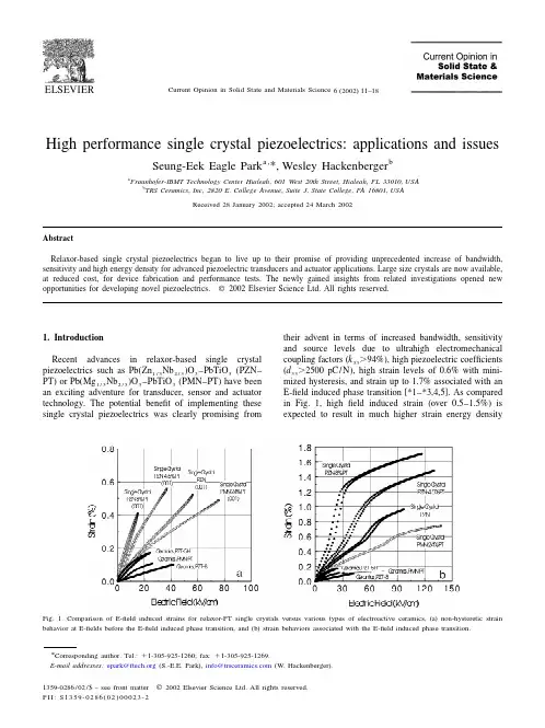
机械设计创造及其自动化毕业论文外文文献翻译INTEGRATION OF MACHINERY译文题目专业机械设计创造及其自动化外文资料翻译INTEGRATION OF MACHINERY(From ELECTRICAL AND MACHINERY INDUSTRY)ABSTRACTMachinery was the modern science and technology development inevitable result, this article has summarized the integration of machinery technology basic outline and the development background .Summarized the domestic and foreign integration of machinery technology present situation, has analyzed the integration of machinery technology trend of development.Key word: integration of machinery ,technology, present situation ,product t,echnique of manufacture ,trend of development0. Introduction modern science and technology unceasing development, impelled different discipline intersecting enormously with the seepage, has caused the project domain technological revolution and the transformation .In mechanical engineering domain, because the microelectronic technology and the computer technology rapid development and forms to the mechanical industry seepage the integration of machinery, caused the mechanical industry the technical structure, the product organization, the function and the constitution, the production method and the management systemof by machinery for the characteristic integration ofdevelopment phase.1. Integration of machinery outline integration of machinery is refers in the organization new owner function, the power function, in the information processing function and the control function introduces the electronic technology, unifies the system the mechanism and the computerization design and the software which constitutes always to call. The integration of machinery development also has become one to have until now own system new discipline, not only develops along with the science and technology, but also entrusts with the new content .But its basic characteristic may summarize is: The integration of machinery is embarks from the system viewpoint, synthesis community technologies and so on utilization mechanical technology, microelectronic technology, automatic control technology, computer technology, information technology, sensing observation and control technology, electric power electronic technology, connection technology, information conversion technology as well as software programming technology, according to the system function goal and the optimized organization goal, reasonable disposition and the layout various functions unit, in multi-purpose, high grade, redundant reliable, in the low energy consumption significance realize the specific function value, and causes the overall system optimization the systems engineering technology .From this produces functional system, then becomes an integration of machinery systematic or the integration of machinery product. Therefore, of coveringtechnology is based on the above community technology organic fusion one kind of comprehensive technology, but is not mechanical technical, the microelectronic technology as well as other new technical simple combination, pieces together .This is the integration of machinery and the machinery adds the machinery electrification which the electricity forms in the concept basic difference .The mechanical engineering technology has the merely technical to develop the machinery electrification, still was the traditional machinery, its main function still was replaces with the enlargement physical strength .But after develops the integration of machinery, micro electron installment besides may substitute for certain mechanical parts the original function, but also can entrust with many new functions,like the automatic detection, the automatic reduction information, demonstrate the record, the automatic control and the control automatic diagnosis and the protection automatically and so on .Not only namely the integration of machinery product is human's hand and body extending, human's sense organ and the brains look, has the intellectualized characteristic is the integration of machinery and the machinery electrification distinguishes in the function essence.2. Integration of machinery development condition integration of machinery development may divide into 3 stages roughly.20th century 60's before for the first stage, this stage is called the initial stage .In this time, the people determination not on own initiative uses the electronic technology the preliminary achievement to consummate the mechanical product the performance .Specially in Second World War period, the war has stimulated the mechanical product and the electronic technology union, these mechanical and electrical union military technology, postwar transfers civilly, to postwar economical restoration positive function .Developed and the development at that time generally speaking also is at the spontaneouscondition .Because at that time the electronic technology development not yet achieved certain level, mechanical technical and electronic technology union also not impossible widespread and thorough development, already developed the product was also unable to promote massively. The 20th century 70~80 ages for the second stage, may be called the vigorous development stage .This time, the computer technology, the control technology, the communication development, has laid the technology base for the integration of machinery development . Large-scale, ultra large scale integrated circuit and microcomputer swift and violent development, has provided the full material base for the integration of machinery development .This time characteristic is :①A mechatronics word first generally is accepted in Japan, probably obtains the quite widespread acknowledgment to 1980s last stages in the worldwide scale ;②The integration of machinery technology and the product obtained the enormous development ;③The various countries start to the integration of machinery technology and the product give the very big attention and the support. 1990s later periods, started the integration of machinery technology the new stagewhich makes great strides forward to the intellectualized direction, the integration of machinery enters the thorough development time .At the same time, optics, the communication and so on entered the integration of machinery, processes the technology also zhan to appear tiny in the integration of machinery the foot, appeared the light integration of machinery and the micro integration of machinery and so on the new branch; On the other hand to the integration of machinery system modeling design, the analysis and the integrated method, the integration of machinery discipline system and the trend of development has all conducted the thorough research .At the same time, because the hugeprogress which domains and so on artificial intelligence technology, neural network technology and optical fiber technology obtain, opened the development vast world for the integration of machinery technology .These research, will urge the integration of machinery further to establish the integrity the foundation and forms the integrity gradually the scientific system. Our country is only then starts from the beginning of 1980s in this aspect to study with the application .The State Councilsummary had considered fully on international the influence which and possibly brought from this about the integration of machinery technology developmenttrend .Many universities, colleges and institutes, the development facility and some large and middle scale enterprises have done the massive work to this technical development and the application, does not yield certain result, but and so on the advanced countries compared with Japan still has the suitable disparity.3. Integration of machinery trend of development integrations of machinery are the collection machinery, the electron, optics, the control, the computer, the information and so on the multi-disciplinary overlapping syntheses, its development and the progress rely on and promote the correlation technology development and the progress .Therefore, the integration of machinery main development direction is as follows:3.1 Intellectualized intellectualizations are 21st century integration of machinery technological development important development directions .Theartificial intelligence obtains day by day in the integration of machinery constructor's research takes, the robot and the numerical control engine bedis to the machine behavior description, is in the control theory foundation, the absorption artificial intelligence, the operations research, the computer science, the fuzzy mathematics, the psychology, the physiology and the chaos dynamics and so on the new thought, the new method, simulate the human intelligence, enable it to have abilities and so on judgment inference, logical thinking, independent decision-making, obtains the higher control goal in order to .Indeed, enable the integration of machinery product to have with the human identical intelligence, is not impossible, also is nonessential .But, the high performance, the high speed microprocessor enable the integration of machinery product to have preliminary intelligent or human's partial intelligences, then is completely possible and essential.In the modern manufacture process, the information has become the control manufacture industry the determining factor, moreover is the most active actuation factor .Enhances the manufacture system information-handling capacity to become the modern manufacture science development a key point .As a result of the manufacture system information organization and structure multi-level, makes the information the gain, the integration and the fusion presents draws up the character, information measure multi-dimensional, as well as information organization's multi-level .In the manufacture information structural model, manufacture information uniform restraint, dissemination processing and magnanimous data aspects and so on manufacture knowledge library management, all also wait for further break through.Each kind of artificial intelligence tool and the computation intelligence method promoted the manufacture intelligence development in the manufacture widespread application .A kind based on the biological evolution algorithm computation intelligent agent, in includes thescheduling problem in the combination optimization solution area of technology, receives the more and more universal attention, hopefully completes the combination optimization question when the manufacture the solution speed and the solution precision aspect breaks through the question scale in pairs the restriction .The manufacture intelligence also displays in: The intelligent dispatch, the intelligent design, the intelligent processing, the robot study, the intelligent control, the intelligent craft plan, the intelligent diagnosis and so on are various These question key breakthrough, may form the product innovation the basic research system. Between 2 modern mechanical engineering front science different science overlapping fusion will have the new science accumulation, the economical development and society's progress has had the new request and the expectation to the science and technology, thus will form the front science .The front science also has solved and between the solution scientific question border area .The front science has the obvious time domain, the domain and the dynamic characteristic .The project front science distinguished in the general basic science important characteristic is it has covered the key science and technology question which the project actual appeared.Manufacture system is a complex large-scale system, for satisfies the manufacture system agility, the fast response and fast reorganization ability, must profit from the information science, the life sciences and the social sciences and so on the multi-disciplinary research results, the exploration manufacture system new architecture, the manufacture pattern and the manufacture system effective operational mechanism .Makes the system optimization the organizational structure and the good movement condition is makes the system modeling , the simulation and the optimized essential target .Not only the manufacture system new architecture to makes the enterprise the agility and may reorganize ability to the demand response ability to have the vital significance, moreover to made the enterprise first floor production equipment the flexibility and may dynamic reorganization ability set a higher request .The biological manufacture view more and more many is introduced the manufacture system, satisfies the manufacture system new request.The study organizes and circulates method and technique of complicated system from the biological phenomenon, is a valid exit which will solve many hard nut to cracks that manufacturing industry face from now on currently .Imitating to living what manufacturing point is mimicry living creature organ of from the organization, from match more, from growth with from evolution etc. function structure and circulate mode of a kind of manufacturing system and manufacturing process.The manufacturing drives in the mechanism under, continuously by one's own perfect raise on organizing structure and circulating mode and thus to adapt the process of[with] ability for the environment .For from descend but the last product proceed together a design and make a craft rules the auto of the distance born, produce system of dynamic state reorganization and product and manufacturing the system tend automatically excellent provided theories foundation and carry out acondition .Imitate to living a manufacturing to belong to manufacturing science and life science of"the far good luck is miscellaneous to hand over", it will produce to the manufacturing industry for 21 centuries huge of influence .机电一体化摘要机电一体化是现代科学技术发展的必然结果,本文简述了机电一体化技术的基本概要和发展背景。
Metal heat treatmentA, annealingIn front of the description lengba processing materials and softening plastic treatment methods, it has been used the word, the word annealing with similar meanings. The purpose is to reduce completely annealing, hardness, plastic, sometimes also increased to improve the cutting performance, high this steel is difficult to processing. This method is used to reduce heat stress, refined grains, improve the structure of the material.Annealing is not always can improve the cutting machining, cutting processing a word used to describe several factors, including material cutting when good finish (i.e. smaller surface roughness - the ability of the translator. When fully annealing, ordinary low hardness, low intensity of cutting resistance smaller, less, but usually due to the plasticity and toughness is too big to chip away when the surface of workpiece surface of workpiece surface quality, scratch, leads to poor cutting processing. For this kind of steel, annealing may not be the most appropriate treatment. Many of the most high and cutting steel processing usually can be greatly improved by annealing except in the soft, because of their condition, high hardness and strength for processing.And the annealing method is GongXi just slow to the steel wire, insulation above about for a period of time, make the same temperature uniformity, forming materials, then the austenitic or buried with furnace lime or other insulating materials in slow cooling. To precipitation of ferrite and pearlite bulky iron, steel in the soft, the strain of toughness and minimum, must slow cooling.Second, normalizingHow much is the fire of similar purposes, but not the annealing steel soft and fine pearlite state. Not bulky. Steel is refined grains, fire can release of stress, improve structural homogeneity and restore some plastic, high toughness. This method is often used to improve cutting machining, reduce stress, reduce part machining or limitation of deformation.Is the fire will chromatography method is GuoGongXiGang steel or slow heatedto Ac3 respectively, Accm line or on-line insulation for a period of time to form, and in the austenitic stationary air slow cooling. Should notice more, GongXi composition of carbon steel needs to be heated to Accm line above, not Ac1 line above the annealing. The purpose is in the process of austenitic to dissolve all cementite, thus to minimize the boundaries on hard and brittle iron carbon compounds, and get little grain of ferrite pearlite, minimum free cementite and freedom.Third, the ball annealingThrough the steel ball annealing can get minimum hardness and the biggest plastic, it can make the iron carbon compounds with small globular distribution in ferritic matrix. In order to make the ball easier small particles, usually for fire steel ball annealing. Ball annealing available in several different methods, but all the methods are needed in A1 line near (usually slightly low temperature preservation) for a long time, make the iron carbon compounds formed more stable, low level of small ball.Ball annealing method of the main objective is to improve the cutting processing, and drawing of hardened steel pretreatment, make it more uniform structure quenching. Because of the heat treatment for a long time, so the cost is higher than that of ball annealing is common or annealing.Four, steel sclerosisThe most hardened steel heat treatment method is based on the production of martensite high. Therefore, the first step to most other treatment with commonly used method -- austenitic. YaGongXiGang heated to Ac1 liquidus temperature, heat preservation, more about that temperature uniformly, austenitic evenly. GuoGongXiGang Ac1 above liquidus temperature preservation in steel, while about still remain iron carbon compounds.The second step is to avoid rapid cooling in the nose produces isothermal curve transformation pearlite. The cooling speed depends on the temperature and hardened steel quenching medium heat can be taken away from the surface of the ability of heat transfer and steel itself. Table 1-11 is some common medium and cooling method, cooling ability of the sequence.High temperature gradient produces high stress, deformation and cracking causes,so only in the very need to produce quenching specific structures are used. When the quenching heat uniform, care must be taken to reduce the heat stress diffusion. For example, a thin stick to end its vertical quenching, is inserted into the cooling medium, so whole section and temperature changes. If the shape of a side of the workpiece cooling, and on the other side of the earlier than size change is likely to cause high stress, produce plastic flow and permanent deformation.With several special quenching method can reduce stress, deformation and cracking quenching decreases. One called hierarchical quenching, the method is: will the austenitic steel in temperature is higher than that of martensite transformation temperature (Ms), salt bath time until the temperature uniformity, at the beginning of forming bainite, then put before air cooling, heat generated from the start when the same hardware quenching cracking, martensite and warpage cause of high thermal stress or eliminate stress have been quenched.In a similar method of temperature, then, is called the isothermal quenching (austenitic steel in salt bath), keep for a long time, the result is formed with the isothermal bainite. Bainite structure in the same ingredients as the formation of martensite hard, but in normal hardened steel, reduce the heat shock, by further processing, unnecessary in high hardness can be obtained when good impact toughness.Five, temperingTo adjust hardened steel used the third step is often backfire. Besides the isothermal quenching steel quenching condition usually used in most all can use in production. To produce martensite steel to quench make hard, macro and micro stress, stress, low plasticity materials. To reduce the harm that can be heated to steel again by low-temperature shift (A1) below a certain temperature. Hardened steel structure change of tempering time and temperature is the function of temperature, which is the most important. Must be hardened piece.it is emphasized, method, but the reverse is true. Steel is tempered by heat treatment of hardened steel, through the tempering of heating, to release stress again, soften and improve plastic.The structural change and tempering causes change depending on performance of the heating temperature steel back. The higher the temperature, the temperatureeffect, so the choice is often sacrificed for the hardness and strength plasticity and toughness. Again, to quench heating to influence of carbon-steel, in between, structure, changes will occur in the above, the structure and properties of the significant changes. In the next time the temperature of the A1 heat will produce and process of ball annealing of similar structures.In industry, usually avoid to scope, because the tempering within the scope of tempering steel often produced unexplained brittleness or plastic loss. Some alloy in to scope, also can produce "temper brittleness, especially from" (or by) the temperature range slow cooling will appear. When these steel heat temper, they must usually heated to rapid cooling and above. Of course, from the temperature of cold won't produce sclerosis, fast because no austenitic.金属热处理一、退火在前面描述冷拔加工材料的软化并重新获得塑性的热处理方法时,就已使用退火这个词,该词具有相似的意义。
翻译部分英文部分ADV ANCED MACHINING PROCESSESAs the hardware of an advanced technology becomes more complex, new and visionary approaches to the processing of materials into useful products come into common use. This has been the trend in machining processes in recent years.. Advanced methods of machine control as well as completely different methods of shaping materials have permitted the mechanical designer to proceed in directions that would have been totally impossible only a few years ago.Parallel development in other technologies such as electronics and computers have made available to the machine tool designer methods and processes that can permit a machine tool to far exceed the capabilities of the most experienced machinist.In this section we will look at CNC machining using chip-making cutting tools. CNC controllers are used to drive and control a great variety of machines and mechanisms, Some examples would be routers in wood working; lasers, plasma-arc, flame cutting, and waterjets for cutting of steel plate; and controlling of robots in manufacturing and assembly. This section is only an overview and cannot take the place of a programming manual for a specific machine tool. Because of the tremendous growth in numbers and capability of comp uters ,changes in machine controls are rapidly and constantly taking place. The exciting part of this evolution in machine controls is that programming becomeseasier with each new advanced in this technology.Advantages of Numerical ControlA manually operated machine tool may have the same physical characteristics as a CNC machine, such as size and horsepower. The principles of metal removal are the same. The big gain comes from the computer controlling the machining axes movements. CNC-controlled machine tools can be as simple as a 2-axis drilling machining center (Figure O-1). With a dual spindle machining center, the low RPM, high horsepower spindle gives high metal removal rates. The high RPM spindle allows the efficient use of high cutting speed tools such as diamonds and small diameter cutters (Figure O-2). The cutting tools that remove materials are standard tools such as milling cutters, drills, boring tools, or lathe tools depending on the type of machine used. Cutting speeds and feeds need to be correct as in any other machining operation. The greatest advantage in CNC machining comes from the unerring and rapid positioning movements possible. A CNC machine does dot stop at the end of a cut to plan its next move; it does not get fatigued; it is capable of uninterrupted machining error free, hour after hour. A machine tool is productive only while it is making chips.Since the chip-making process is controlled by the proper feeds and speeds, time savings can be achieved by faster rapid feed rates. Rapid feeds have increased from 60 to 200 to 400 and are now often approaching 1000 inches per minute (IPM). These high feed rates can pose a safety hazard to anyone within the working envelope of the machine tool.Complex contoured shapes were extremely difficult to product prior to CNC machining .CNC has made the machining of these shapes economically feasible. Design changes on a part are relatively easy to make by changing the program that directs the machine tool.A CNC machine produces parts with high dimensional accuracy and close tolerances without taking extra time or special precautions, CNC machines generally need less complex work-holding fixtures, which saves time by getting the parts machined sooner. Once a program is ready and production parts, each part will take exactly the same amount of time as the previous one. This repeatability allows for a very precise control of production costs. Another advantage of CNC machining is the elimination of large inventories; parts can be machined as needs .In conventional production often a great number of parts must be made at the same time to be cost effective. With CNC even one piece can be machined economically .In many instances, a CNC machine can perform in one setup the same operations that would require several conventional machines.With modern CNC machine tools a trained machinist can program and product even a single part economically .CNC machine tools are used in small and large machining facilities and range in size from tabletop models to huge machining centers. In a facility with many CNC tools, programming is usually done by CNC programmers away from the CNC tools. The machine control unit (MCU) on the machine is then used mostly for small program changes or corrections. Manufacturing with CNC tools usually requires three categories of persons. The first is the programmer, who is responsible for developing machine-ready code. The next person involved is the setup person, who loads the raw stork into the MCU, checks that the co rrect tools are loaded, and makes the first part. The third person is the machine and unloads the finished parts. In a small company, one person is expected to perform all three of these tasks.CNC controls are generally divided into two basic categories. One uses a ward address format with coded inputs such as G and M codes. The other users a conversational input; conversational input is also called user-friendly or prompted input. Later in this section examples of each of these programming formats in machining applications will be describes.CAM and CNCCAM systems have changed the job of the CNC programmer from one manually producing CNC code to one maximizing the output of CNC machines. Since CNC machine tools are made by a great number of manufacturers, many different CNC control units are in use. Control units from different manufacturers use a variety of program formats and codes. Many CNC code words are identical for different controllers, but a great number vary from one to another.To produce an identical part on CNC machine tools with different controllers such as one by FANCU, OKUMA or DYNAPATH, would require completely different CNC codes. Each manufacturer is constantly improving and updating its CNC controllers. These improvements often include additional code words plus changes in how the existing code works.A CAM systems allows the CNC programmer to concentrate on the creation of an efficient machining process, rather then relearning changed code formats. A CNC programmer looks atthe print of a part and then plans the sequence of machining operations necessary to make it (Figure O-3). This plan includes everything, from the selection of possible CNC machine tools, to which tooling to use, to how the part is held while machining takes place. The CNC programmer has to have a thorough understanding of all the capacities and limitations of the CNC machine tools that a program is to be made for. Machine specifications such as horsepower, maximum spindle speeds, workpiece weight and size limitations, and tool changer capacity are just some of the considerations that affect programming.Another area of major importance to the programmer is the knowledge of machining processes. An example would be the selection of the surface finish requirement specified in the part print. The sequence of machining processes is critical to obtain acceptable results. Cutting tool limitations have to be considered and this requires knowledge of cutting tool materials, tool types, and application recommendations.A good programmer will spend a considerable amount of time in researching the rapidly growing volume of new and improved tools and tool materials. Often the tool that was on the cutting edge of technology just two years ago is now obsolete. Information on new tools can come from catalogs or tool manufacturers' tooling engineers. Help in tool selection or optimum tool working conditions can also be obtained from tool manufacturer software. Examples would be Kennametal's "TOOLPRO", software designed to help select the best tool grade, speed, and feed rates for different work materials in turning application. Another very important feature of "TOOLPRO" is the display of the horsepower requirement for each machining selection. This allow the programmer to select a combination of cutting speed, feed rate, and depth of cut that equals the machine's maximum horsepower for roughing cuts. For a finishing cut, the smallest diameter of the part being machined is selected and then the cutting speed varied until the RPM is equal to the maximum RPM of the machine. This helps in maximizing machining efficiency. Knowing the horsepower requirement for a cut is critical if more than one tool is cutting at the same time.Software for a machining center application would be Ingersoll Tool Company's "Actual Chip Thickness", a program used to calculate the chip thickness in relation to feed-per-tooth for a milling cutter, especially during a shallow finishing cut. Ingersoll's "Rigidity Analysis" software ealculates tool deflection for end mills as a function of tool stiffness and tool force.To this point we looked at some general qualifications that a programmer should possess. Now we examine how a CAM system works. Point Control Company's SmartCam system uses the following approach. First, the programmer makes a mental model of the part to be machined. This includes the kind of machining to be performed-turning or milling. Then the part print is studied to develop a machining sequence, roughing and finishing cuts, drilling, tapping, and boring operations. What work-holding device is to be used, a vise or fixture or clamps? After these considerations, computer input can be started. First comes the creation of a JOBPLAN. This JOBPLAN consists of entries such as inch or metric units, machine type, part ID, type of workpiece material, setup notes, and a description of the required tools.This line of information describes the tool by number, type, and size and includes theappropriate cutting speed and feed rate. After all the selected tools are entered, the file is saved.The second programming step is the making of the part. This represents a graphic modeling of the projected machining operation. After selecting a tool from the prepared JOBPLAN, parameters for the cutting operation are entered. For a drill, once the coordinate location of the hole and the depth are given, a circle appears on that spot. If the location is incorrect, the UNDO command erases this entry and allows you to give new values for this operation. When an end mill is being used, cutting movements (toolpath) are usually defined as lines and arcs. As a line is programmed, the toolpath is graphically displayed and errors can be corrected instantly.At any time during programming, the command SHOWPATH will show the actual toolpath for each of the programmed tools. The tools will be displayed in the sequence in which they will be used during actual machining. If the sequence of a tool movement needs to be changed, a few keystrokes will to that.Sometimes in CAM the programming sequence is different from the actual machining order. An example would be the machining of a pocket in a part. With CAM, the finished pocket outline is programmed first, then this outline is used to define the ro ughing cuts to machine the pocket. The roughing cuts are computer generated from inputs such as depth and width of cut and how much material to leave for the finish cut. Different roughing patterns can be tried out to allow the programmer to select the most efllcient one for the actual machining cuts. Since each tool is represented by a different color, it is easy to observe the toolpath made by each one.A CAM system lets the programmer view the graphics model from varying angles, such as a top, front, side, or isometric view. A toolpath that looks correct from a top view, may show from a front view that the depth of the cutting tool is incorrect. Changes can easily be made and seen immediately.When the toolpath and the sequence of operations are satisfactory, machine ready code has to be made. This is as easy as specifying the CNC machine that is to be used to machine the part. The code generator for that specific CNC machin e during processing accesses four different files. The JOBPLAN file for the tool information and the GRAPHICE file for the toolpath and cutting sequence. It also uses the MACHINE DEFINE file which defines the CNC code words for that specific machine. This file also supplies data for maximum feed rates, RPM, toolchange times, and so on. The fourth file taking part in the code generating process is the TEMPLATE file. This file acts like a ruler that produces the CNC code with all of its parts in the right place and sequence. When the code generation is complete, a projected machining time is displayed. This time is calculated from values such as feed rates and distances traveled, noncutting movements at maximum feed rates between points, tool change times, and so on. The projected machining time can be revised by changing tooling to allow for higher metal removal rates or creating a more efficient toolpath. This display of total time required can also be used to estimate production costs. If more then one CNC machine tool is available to machine this part, making code and comparing the machining time may show that one machine is more efficient than the others.CAD/CAMAnother method of creating toolpath is with the use of a Computer-aided Drafting (CAD) file. Most machine drawings are created using computers with the description and part geometry stored in the computer database. SmartCAM, though its CAM CONNECTION, will read a CAD file and transfer its geometry represents the part profile, holes, and so on. The programmer still needs to prepare a JOBPLAN with all the necessary tools, but instead of programming a profile line by line, now only a tool has to be assigned to an existing profile. Again, using the SHOWPA TH function will display the toolpath for each tool and their sequence. Constant research and developments in CAD/CAM interaction will change how they work with each other. Some CAD and CAM programs, if loaded on the same computer, make it possible to switch between the two with a few keystrokes, designing and programming at the same time.The work area around the machine needs to be kept clean and clear of obstructions to prevent slipping or tripping. Machine surfaces should not be used as worktables. Use proper lifting methods to handle heavy workpieces, fixtures, or heavy cutting tools. Make measurements only when the spindle has come to a complete standstill. Chips should never be handled with bare hands.Before starting the machine make sure that the work-holding device and the workpiece are securely fastened. When changing cutting tools, protect the workpiece being machined from damage, and protect your hands from sharp cutting edges. Use only sharp cutting tools. Check that cutting tools are installed correctly and securely.Do not operate any machine controls unless you understand their function and what the y will do.The Early Development Of Numerically Controlled Machine ToolsThe highly sophisticated CNC machine tools of today, in the vast and diverse range found throughout the field of manufacturing processing, started from very humble beginnings in a number of the major industrialized countries. Some of the earliest research and development work in this field was completed in USA and a mention will be made of the UK's contribution to this numerical control development.A major problem occurred just after the Second World War, in that progress in all areas of military and commercial development had been so rapid that the levels of automation and accuracy required by the modern industrialized world could not be attained from the lab our intensive machines in use at that time. The question was how to overcome the disadvantages of conventional plant and current manning levels. It is generally ackonwledged that the earliest work into numerical control was the study commissioned in 1947 by the US governme nt. The study's conclusion was that the metal cutting industry throughout the entire country could not copy with the demands of the American Air Force, let alone the rest of industry! As a direct result of the survey, the US Air Force contracted the Persons Corporation to see if they could develop a flexible, dynamic, manufacturing system which would maximize productivity. TheMassachusetts Institute of Technology (MIT) was sub-contracted into this research and development by the Parsons Corporation, during the period 1949-1951,and jointly they developed the first control system which could be adapted to a wide range of machine tools. The Cincinnati Machine Tool Company converted one of their standard 28 inch "Hydro-Tel" milling machines or a three-axis automatic milling made use of a servo-mechanism for the drive system on the axes. This machine made use of a servomechanism for the drive system on the axes, which controlled the table positioning, cross-slide and spindle head. The machine cab be classified as the first truly three axis continuous path machine tool and it was able to generate a required shape, or curve, by simultaneous slide way motions, if necessary.At about the same times as these American advances in machine tool control were taking Place, Alfred Herbert Limited in the United Kingdom had their first Mutinous path control system which became available in 1956.Over the next few years in both the USA and Europe, further development work occurred. These early numerical control developments were principally for the aerospace industry, where it was necessary to cut complex geometric shapes such as airframe components and turbine blades. In parallel with this development of sophisticated control systems for aerospace requirements, a point-to-point controller was developed for more general machining applications. These less sophisticated point-to-point machines were considerably cheaper than their more complex continuous path cousins and were used when only positional accuracy was necessary. As an example of point-to-point motion on a machine tool for drilling operations, the typical movement might be fast traverse of the work piece under the drill's position-after drilling the hole, anther rapid move takes place to the next hole's position-after retraction of the drill. Of course, the rapid motion of the slideways could be achieved by each axis in a sequential and independent manner, or simultaneously. If a separate control was utilisec for each axis, the former method of table travel was less esse ntial to avoid any backlash in the system to obtain the required degree of positional accuracy and so it was necessary that the approach direction to the next point was always the same.The earliest examples of these cheaper point-to-point machines usually did not use recalculating ball screws; this meant that the motions would be sluggish, and sliderways would inevitably suffer from backlash, but more will be said about this topic later in the chapter.The early NC machines were, in the main, based upon a modified milling machine with this concept of control being utilized on turning, punching, grinding and a whole host of other machine tools later. Towards the end of the 1950s,hydrostatic slideways were often incorporated for machine tools of highly precision, which to sonic extent overcame the section problem associated with conventional slideway response, whiles averaging-out slideway inaccuracy brought about a much increased preasion in the machine tool and improved their control characteristics allows "concept of the machining center" was the product of this early work, as it allowed the machine to manufacture a range of components using a wide variety of machining processes at a single set-up, without transfer of workpieces to other variety machine tools. A machining center differed conceptually in its design from that of a milling machine, In that thecutting tools could be changed automatically by the transfer machanism, or selector, from the magazine to spindle, or vice versa.In this ductively and the automatic tool changing feature enabled the machining center to productively and efficiently machine a range of components, by replacing old tools for new, or reselecting the next cutter whilst the current machining process is in cycle.In the mid 1960s,a UK company, Molins, introduced their unique "System 24" which was meant represent the ability of a system to machine for 24 hours per day. It could be thought of as a "machining complex" which allowed a series of NC single purpose machine tools to be linked by a computerized conveyor system. This conveyor allowed the work pieces to be palletized and then directed to as machine tool as necessary. This was an early, but admirable, attempt at a form of Flexible manufacturing System concept, but was unfortunately doomed to failure. Its principal weakness was that only a small proportion of component varieties could be machine at any instant and that even fewer work pieces required the same operations to be performed on them. These factors meant that the utilization level was low, coupled to the fact that the machine tools were expensive and allowed frequent production bottlenecks of work-in-progress to arise, which further slowed down the whole operation.The early to mid-1970s was a time of revolutionary in the area of machine tool controller development, when the term computerized numerical control (CNC) became a reality. This new breed of controllers gave a company the ability to change work piece geometries, together with programs, easily with the minimum of development and lead time, allowing it to be economically viable to machine small batches, or even one-off successfully. The dream of allowing a computerized numerical controller the flexibility and ease of program editing in a production environment became a reality when two ralated factors occurred.These were:the development of integrated circuits, which reduces electronics circuit size, giving better maintenance and allowing more standardization of desing; that general purpose computers were reduced in size coupled to the fact that their cost of production had fallen considerably.The multipie benefits of cheaper electorics with greater reliability have result in the CNC fitted to the machine tools today, with the power and sophistication progtessing considerably in the last few years, allowing an almost artificial intelligence(AI) to the latest systems. Over the years, the machine tools builders have produced a large diversity in the range of applications of CNC and just some of those development will be reviewed in V olume Ⅲ。
附录Process PlanningThe product design is the plan for the product and its components and subassemblies.To convert the product design into a physical entity ,a manufacturing plan is needed .The activity of developing such a plan is called process planning .It is the link between product design and manufacturing .Process planning involves determining the sequence of processing and assembly steps that must be accomplished to make the product .In the present chapter ,we examine processing planning and several related topics.At the outset ,we should distinguish between process planning and production planning ,which is covered in the following chapter. Process planning is concerned with the engineering and technological issues of how to make the products and its parts. What types of equipment and tooling are required to fabricate the parts and assemble the product ? Production planning is concerned with the logistics of making the product .After process planning is concerned with ordering the materials and obtaining the resources required to make the product in sufficient quantities to satisfy demand for it.Process PlanningProcess planning involves determining the most appropriate manufacturing and assembly processes and the sequence in which they should be accomplished to produce a given part or product according to specifications set forth in the product design documentation.The scope and variety of processes that can be planned are generally limited by the available processing equipment and technological capabilities of the company of plant .Parts that cannot be made internally must be purchased from outside vendors. It should be mentioned that the choice of processes is also limited by the details of the product design.This is apoint we will return to later.Process planning is usually accomplished by manufacturing engineers .(Other titles include in industrial engineer.) The process planner must be familiar with the particular manufacturing processes available in the factory and be able to interpret engineering drawings .Based on the planner’s knowledge,skill,and experience ,the processing steps are developed in the most logical sequence to make each part .Following is a list of the many decisions and details usually include within the scope of process planning :.Interpretation of design drawings.The part of product design must be analyzed (materials,dimensions,tolerances ,surface finished,etc.) at the start of the process planning procedure..Process and sequence.The process planner must select which processes are required and their sequence.A brief description of processing steps must be prepared..Equipment selection . In general , process planners must develop plans that utilize existing equipment in the plant .Otherwise ,the component must be purchased ,or an investment must be made in new equipment ..Tools ,dies,molds,fixtures,and gages.The process must decide what tooling is required for each processing step.The actual design and fabrication of these tools is usually delegated to a tool design department and tool room ,or an outside vendor specializing in that type of tool is contacted.Methods analysis .Workplace layout ,small tools ,hoists for lifting heavy parts ,even in some cases hand and body motions must be specified for manual operations .The industrial engineering department is usually responsible for this area..Work standards.Work measurement techniques are used to set time standards for each operation ..Cutting tools and cutting conditions.These must be specified for machiningoperations ,often with reference to standard handbook recommendations.Process Planning for partsFor individual parts,the processing sequence is documented on a form called a route sheet .(Not all companies use the name route sheet ;another name is “operation sheet .”)Just as engineering drawings are used to specify the product design ,route sheets are used to specify the process plan .They are counterparts,one for product design ,the other for manufacturing .A typical route sheet ,illustrated in Fig.21.1,includes the following information: (1) all operations to be performed on the work part ,listed in the order in which they should be performed ; (2) a brief description of each operation indicating the processing to be accomplished,with references to dimensions and tolerances on the part drawing; (3) the specific machines on which the work to be done; and (4) special tooling such as dies molds ,cutting tools,jigs or fixtures ,and gages.Some companies also include setup times ,cycle time standards,and other data.It is called a route sheet because the processing sequence defines the route that the part must follow in the factory .Some of the guidelines in preparing a route sheet are listed in Table 21-1.Decisions on process to be used to fabricate a given part are based largely on the starting material for the part .This starting material is selected by the product designer.Once the material has been specified ,the range of the possible processing operation is reduced considerably .The product designer’s decisions on starting material are based primarily on functional requirements ,although economics and manufacturability a role in the selection.A typical processing sequence to fabricate an individual part consists of : (1) a basic process,(2)secondary processes ,(3) operations to enhance physical properties,and (4)finishing operations.The sequence is shown in Fig.21.2. A basic process determines the starting geometry of the workpart.Metal casting ,plastic molding ,and roling of sheet metal are examples of basic processes.The starting geometry must often be refined by secondaryprocesses,operations that transform the starting geometry (or close to final geometry ).The secondary geometry processes that might be used are closely correlated to the basic process that provides the starting geometry.When sand casting is the basic processes,machining operations are generally the second processes .When a rolling mill produces sheet metal,stamping operations such as punching and bending are the secondary processes.When plastic injection molding is the basic process ,secondary operations are often unnecessary,because most of the geometric features that would otherwise require machining can be created by the molding operation.Plastic molding and other operation that require no subsequent secondary processing are called net shape processes.Operations that require some but not much secondary processing (usually machining ) are referred to as near net shape processes.Some impression die forgings are in this category .These parts can often be shaped in the forging operation(basic processes)so that minimal machining (secondary processing )is required .Once the geometry has been established ,the next step for some parts is to improve their mechanical and physical properties .Operations to enhance properties do not alter the geometry of the part;instead,they alter physical properties .Heat treating operations on metal parts are the most common examples .Similar heating treatments are performed on glass to produce tempered glass.For most manufactured parts ,these property-enhancing operations are not required in the processing sequence ,as indicated by the alternative arrow path in Fig.21.2.Finally finish operations usually provide a coat on the work parts (or assembly )surface. Examples inclued electroplating ,thin film deposition techniques ,and painting.The purpose of the coating is to enhance appearance ,change color ,or protect the surface from corrosion,abrasion ,and so forth .Finishing operations are not required on many parts ;for example, plastic molding rarely require finishing .When finishing is required ,it is usuallythe final step in the processing sequence .Table 21-2 presents some typical processing sequences for common materials used in manufacturing .In most cases,parts and materials arriving at the factory have complete their basic process.Thus ,the first operation in the process plan follows the basic process that has provided the starting geometry of the part ..For example ,machined parts begain as bar stock or castings or forgings,which are purchased from outide vendors.The process plan begains with the machining operations in the company’s own plant .Stempings begin as sheet metal coils or strips that are bought from the rolling mill.These raw materials are supplied outside sources so that the secondary processes,property-enhancing operations ,and finishing operatios can be performed in the company’s own factory.In addition to the route sheet ,a more detailed description of eac operation is usually prepared. This is filed in the particular production department office where the operation is performed.It lists specific details of the operation ,such as cutting conditionsand toolings(if the operation is machining )and other instructions that may be useful to the amchine operator.The desciptions often include sketches of the machine setup.Processing Planning for AssembliesThe type of assembly method used for a given product depends on factors such as : (1) the anticipated production quantities ;(2) complexity of the assembled product ,for example ,the number of distinct components ;and (3)assembly processes used ,for example ,mechanical assembly versus welding .For a product that is to be made in relatively small quantities ,assembly is usually performed on manual assembly lines .For simple products of a dozen or so components,to be made in large quantities ,automated assembly systems are appropriate .In any case ,there is a precedence order in which the work must be accomplished .The precedence requirements are sometimes portrayed graphically on a precedence diagram.Process planning for assembly involves development of assembly instructions,but in more detail .For low production quantities,the entire assembly is completed at a single station .For high production on an assembly line ,process planning consists of allocating work elements to the individual stations of the line, a procedure called line balancing.The assembly line routes the work unit to individual stations in the proper order as determined by the line balance solution.As in process planning for individual components ,any tools and fixtures required to accomplish an assembly task must be determined ,designed,and built;and the workstation arrangement must belaid out.工艺规程制订产品设计是用于产品,及它的部件装配的计划. 为了把产品设计转换成一个实际物体 ,这需要一个制造计划。