
ASME第八卷第一册2015培训资料
- 格式:pptx
- 大小:2.90 MB
- 文档页数:59

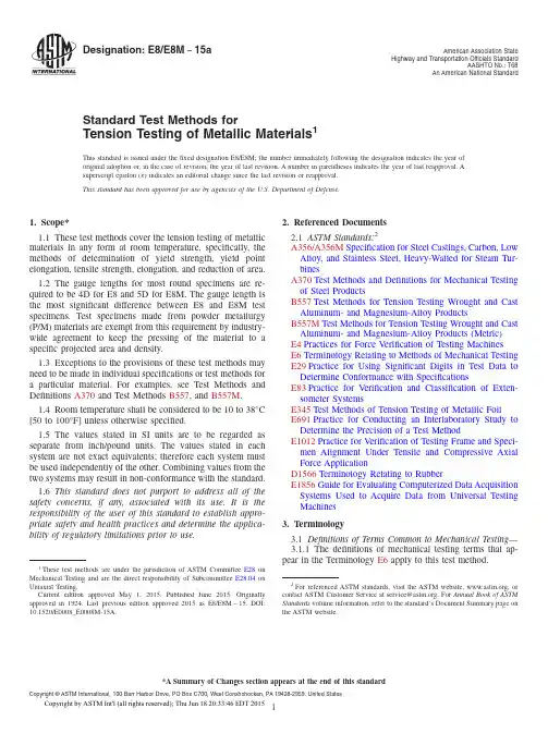
Designation:E8/E8M−15a American Association StateHighway and Transportation Officials StandardAASHTO No.:T68An American National Standard Standard Test Methods forTension Testing of Metallic Materials1This standard is issued under thefixed designation E8/E8M;the number immediately following the designation indicates the year oforiginal adoption or,in the case of revision,the year of last revision.A number in parentheses indicates the year of last reapproval.Asuperscript epsilon(´)indicates an editorial change since the last revision or reapproval.This standard has been approved for use by agencies of the U.S.Department of Defense.1.Scope*1.1These test methods cover the tension testing of metallic materials in any form at room temperature,specifically,the methods of determination of yield strength,yield point elongation,tensile strength,elongation,and reduction of area.1.2The gauge lengths for most round specimens are re-quired to be4D for E8and5D for E8M.The gauge length is the most significant difference between E8and E8M test specimens.Test specimens made from powder metallurgy (P/M)materials are exempt from this requirement by industry-wide agreement to keep the pressing of the material to a specific projected area and density.1.3Exceptions to the provisions of these test methods may need to be made in individual specifications or test methods for a particular material.For examples,see Test Methods and Definitions A370and Test Methods B557,and B557M.1.4Room temperature shall be considered to be10to38°C [50to100°F]unless otherwise specified.1.5The values stated in SI units are to be regarded as separate from inch/pound units.The values stated in each system are not exact equivalents;therefore each system must be used independently of the bining values from the two systems may result in non-conformance with the standard.1.6This standard does not purport to address all of the safety concerns,if any,associated with its use.It is the responsibility of the user of this standard to establish appro-priate safety and health practices and determine the applica-bility of regulatory limitations prior to use.2.Referenced Documents2.1ASTM Standards:2A356/A356M Specification for Steel Castings,Carbon,Low Alloy,and Stainless Steel,Heavy-Walled for Steam Tur-binesA370Test Methods and Definitions for Mechanical Testing of Steel ProductsB557Test Methods for Tension Testing Wrought and Cast Aluminum-and Magnesium-Alloy ProductsB557M Test Methods for Tension Testing Wrought and Cast Aluminum-and Magnesium-Alloy Products(Metric)E4Practices for Force Verification of Testing MachinesE6Terminology Relating to Methods of Mechanical Testing E29Practice for Using Significant Digits in Test Data to Determine Conformance with SpecificationsE83Practice for Verification and Classification of Exten-someter SystemsE345Test Methods of Tension Testing of Metallic FoilE691Practice for Conducting an Interlaboratory Study to Determine the Precision of a Test MethodE1012Practice for Verification of Testing Frame and Speci-men Alignment Under Tensile and Compressive Axial Force ApplicationD1566Terminology Relating to RubberE1856Guide for Evaluating Computerized Data Acquisition Systems Used to Acquire Data from Universal Testing Machines3.Terminology3.1Definitions of Terms Common to Mechanical Testing—3.1.1The definitions of mechanical testing terms that ap-pear in the Terminology E6apply to this test method.1These test methods are under the jurisdiction of ASTM Committee E28on Mechanical Testing and are the direct responsibility of Subcommittee E28.04onUniaxial Testing.Current edition approved May1,2015.Published June2015.Originally approved st previous edition approved2015as E8/E8M–15.DOI: 10.1520/E0008_E0008M-15A.2For referenced ASTM standards,visit the ASTM website,,or contact ASTM Customer Service at service@.For Annual Book of ASTM Standards volume information,refer to the standard’s Document Summary page on the ASTM website.*A Summary of Changes section appears at the end of this standard Copyright©ASTM International,100Barr Harbor Drive,PO Box C700,West Conshohocken,PA19428-2959.United States3.1.1.1These terms include bending strain,constraint, elongation,extensometer,force,gauge length,necking,re-duced section,stress-strain diagram,testing machine,and modulus of elasticity.3.1.2In addition,the following common terms from Termi-nology E6are defined:3.1.3discontinuous yielding,n—in a uniaxial test,a hesita-tion orfluctuation of force observed at the onset of plastic deformation,due to localized yielding.3.1.3.1Discussion—The stress-strain curve need not appear to be discontinuous.3.1.4elongation after fracture,n—the elongation measured byfitting the two halves of the broken specimen together. 3.1.5elongation at fracture,n—the elongation measured just prior to the sudden decrease in force associated with fracture.3.1.6lower yield strength,LYS[FL-2]—in a uniaxial test, the minimum stress recorded during discontinuous yielding, ignoring transient effects.3.1.7reduction of area,n—the difference between the original cross-sectional area of a tension test specimen and the area of its smallest cross section.3.1.7.1Discussion—The reduction of area is usually ex-pressed as a percentage of the original cross-sectional area of the specimen.3.1.7.2Discussion—The smallest cross section may be mea-sured at or after fracture as specified for the material under test.3.1.7.3Discussion—The term reduction of area when ap-plied to metals generally means measurement after fracture; when applied to plastics and elastomers,measurement at fracture.Such interpretation is usually applicable to values for reduction of area reported in the literature when no further qualification is given.(E28.04) 3.1.8tensile strength,S u[FL–2],n—the maximum tensile stress that a material is capable of sustaining.3.1.8.1Discussion—Tensile strength is calculated from the maximum force during a tension test carried to rupture and the original cross-sectional area of the specimen.3.1.9uniform elongation,El u,[%]—the elongation deter-mined at the maximum force sustained by the test piece just prior to necking or fracture,or both.3.1.9.1Discussion—Uniform elongation includes both elas-tic and plastic elongation.3.1.10upper yield strength,UYS[FL-2]—in a uniaxial test, thefirst stress maximum(stress atfirst zero slope)associated with discontinuous yielding at or near the onset of plastic deformation.3.1.11yield point elongation,YPE,n—in a uniaxial test,the strain(expressed in percent)separating the stress-strain curve’s first point of zero slope from the point of transition from discontinuous yielding to uniform strain hardening.3.1.11.1Discussion—If the transition occurs over a range of strain,the YPE end point is the intersection between(a)a horizontal line drawn tangent to the curve at the last zero slope and(b)a line drawn tangent to the strain hardening portion of the stress-strain curve at the point of inflection.If there is no point at or near the onset of yielding at which the slope reaches zero,the material has0%YPE.3.1.12yield strength,YS or S y[FL–2],n—the engineering stress at which,by convention,it is considered that plastic elongation of the material has commenced.3.1.12.1Discussion—This stress may be specified in terms of(a)a specified deviation from a linear stress-strain relationship,(b)a specified total extension attained,or(c) maximum or minimum engineering stresses measured during discontinuous yielding.3.2Definitions of Terms Specific to This Standard:3.2.1referee test,n—test made to settle a disagreement as to the conformance to specified requirements,or conducted by a third party to arbitrate between conflicting results.D1566,D11.084.Significance and Use4.1Tension tests provide information on the strength and ductility of materials under uniaxial tensile stresses.This information may be useful in comparisons of materials,alloy development,quality control,and design under certain circum-stances.4.2The results of tension tests of specimens machined to standardized dimensions from selected portions of a part or material may not totally represent the strength and ductility properties of the entire end product or its in-service behavior in different environments.4.3These test methods are considered satisfactory for ac-ceptance testing of commercial shipments.The test methods have been used extensively in the trade for this purpose.5.Apparatus5.1Testing Machines—Machines used for tension testing shall conform to the requirements of Practices E4.The forces used in determining tensile strength and yield strength shall be within the verified force application range of the testing machine as defined in Practices E4.5.2Gripping Devices:5.2.1General—Various types of gripping devices may be used to transmit the measured force applied by the testing machine to the test specimens.To ensure axial tensile stress within the gauge length,the axis of the test specimen should coincide with the center line of the heads of the testing machine.Any departure from this requirement may introduce bending stresses that are not included in the usual stress computation(force divided by cross-sectional area).N OTE1—The effect of this eccentric force application may be illus-trated by calculating the bending moment and stress thus added.For a standard12.5-mm[0.500-in.]diameter specimen,the stress increase is1.5 percentage points for each0.025mm[0.001in.]of eccentricity.This error increases to2.5percentage points/0.025mm[0.001in.]for a9mm [0.350-in.]diameter specimen and to3.2percentage points/0.025mm [0.001in.]for a6-mm[0.250-in.]diameter specimen.N OTE2—Alignment methods are given in Practice E1012.5.2.2Wedge Grips—Testing machines usually are equipped with wedge grips.These wedge grips generally furnish a satisfactory means of gripping long specimens of ductilemetalandflat plate test specimens such as those shown in Fig.1.If, however,for any reason,one grip of a pair advances farther than the other as the grips tighten,an undesirable bending stress may be introduced.When liners are used behind the wedges,they must be of the same thickness and their faces must beflat and parallel.For best results,the wedges should be supported over their entire lengths by the heads of the testing machine.This requires that liners of several thicknesses be available to cover the range of specimen thickness.For proper gripping,it is desirable that the entire length of the serrated face of each wedge be in contact with the specimen.Proper alignment of wedge grips and liners is illustrated in Fig.2.For short specimens and for specimens of many materials it is generally necessary to use machined test specimens and to use a special means of gripping to ensure that the specimens,when under load,shall be as nearly as possible in uniformly distributed pure axial tension(see5.2.3,5.2.4,and5.2.5). 5.2.3Grips for Threaded and Shouldered Specimens and Brittle Materials—A schematic diagram of a gripping device for threaded-end specimens is shown in Fig.3,while Fig.4 shows a device for gripping specimens with shouldered ends. Both of these gripping devices should be attached to the heads of the testing machine through properly lubricated spherical-seated bearings.The distance between spherical bearings should be as great as feasible.5.2.4Grips for Sheet Materials—The self-adjusting grips shown in Fig.5have proven satisfactory for testing sheet materials that cannot be tested satisfactorily in the usual type of wedge grips.5.2.5Grips for Wire—Grips of either the wedge or snubbing types as shown in Fig.5and Fig.6orflat wedge grips may be used.5.3Dimension-Measuring Devices—Micrometers and other devices used for measuring linear dimensions shall be accurate and precise to at least one half the smallest unit to which the individual dimension is required to be measured.5.4Extensometers—Extensometers used in tension testing shall conform to the requirements of Practice E83for the classifications specified by the procedure section of this test method.Extensometers shall be used and verified to include the strains corresponding to the yield strength and elongation at fracture(if determined).5.4.1Extensometers with gauge lengths equal to or shorter than the nominal gauge length of the specimen(dimension shown as“G-Gauge Length”in the accompanyingfigures)may be used to determine the yield behavior.For specimens without a reduced section(for example,full cross sectional area specimens of wire,rod,or bar),the extensometer gauge length for the determination of yield behavior shall not exceed80% of the distance between grips.For measuring elongation at fracture with an appropriate extensometer,the gauge length of the extensometer shall be equal to the nominal gauge length required for the specimen being tested.6.Test Specimens6.1General:6.1.1Specimen Size—Test specimens shall be either sub-stantially full size or machined,as prescribed in the product specifications for the material being tested.6.1.2Location—Unless otherwise specified,the axis of the test specimen shall be located within the parent material as follows:6.1.2.1At the center for products40mm[1.500in.]or less in thickness,diameter,or distance betweenflats.6.1.2.2Midway from the center to the surface for products over40mm[1.500in.]in thickness,diameter,or distance betweenflats.6.1.3Specimen Machining—Improperly prepared test speci-mens often are the reason for unsatisfactory and incorrect test results.It is important,therefore,that care be exercised in the preparation of specimens,particularly in the machining,to maximize precision and minimize bias in test results.6.1.3.1The reduced sections of prepared specimens should be free of cold work,notches,chatter marks,grooves,gouges, burrs,rough surfaces or edges,overheating,or any other condition which can deleteriously affect the properties to be measured.N OTE3—Punching or blanking of the reduced section may produce significant cold work or shear burrs,or both,along the edges which should be removed by machining.6.1.3.2Within the reduced section of rectangular specimens,edges or corners should not be ground or abraded in a manner which could cause the actual cross-sectional area of the specimen to be significantly different from the calculated area.6.1.3.3For brittle materials,large radiusfillets at the ends of the gauge length should be used.6.1.3.4The cross-sectional area of the specimen should be smallest at the center of the reduced section to ensure fracture within the gauge length.For this reason,a small taper is permitted in the reduced section of each of the specimens described in the following sections.6.1.4Specimen Surface Finish—When materials are tested with surface conditions other than as manufactured,the surface finish of the test specimens should be as provided in the applicable product specifications.N OTE4—Particular attention should be given to the uniformity and quality of surfacefinish of specimens for high strength and very low ductility materials since this has been shown to be a factor in the variability of test results.6.2Plate-Type Specimens—The standard plate-type test specimen is shown in Fig.1.This specimen is used for testing metallic materials in the form of plate,shapes,andflat material having a nominal thickness of5mm[0.188in.]or over.When product specifications so permit,other types of specimens may be used,as provided in6.3,6.4,and6.5.6.3Sheet-Type Specimens:6.3.1The standard sheet-type test specimen is shown in Fig.1.This specimen is used for testing metallic materials in the form of sheet,plate,flat wire,strip,band,hoop,rectangles,and shapes ranging in nominal thickness from0.13to19mm [0.005to0.750in.].When product specifications so permit, other types of specimens may be used,as provided in6.2,6.4, and6.5.DimensionsStandard Specimens Subsize SpecimenPlate-Type,40mm [1.500in.]Wide Sheet-Type,12.5mm[0.500in.]Wide6mm[0.250in.]Widemm[in.]mm[in.]mm[in.]G—Gauge length(Note1and Note2)200.0±0.2[8.00±0.01]50.0±0.1[2.000±0.005]25.0±0.1[1.000±0.003]W—Width(Note3and Note4)40.0±2.0[1.500±0.125,-0.250]12.5±0.2[0.500±0.010]6.0±0.1[0.250±0.005]T—Thickness(Note5)thickness of materialR—Radius offillet,min(Note6)25[1]12.5[0.500]6[0.250] L—Overall length,min(Note2,Note7,and Note8)450[18]200[8]100[4] A—Length of reduced section,min225[9]57[2.25]32[1.25] B—Length of grip section,min(Note9)75[3]50[2]30[1.25] C—Width of grip section,approximate(Note4and Note9)50[2]20[0.750]10[0.375] N OTE1—For the40mm[1.500in.]wide specimen,punch marks for measuring elongation after fracture shall be made on theflat or on the edge of the specimen and within the reduced section.Either a set of nine or more punch marks25mm[1in.]apart,or one or more pairs of punch marks200 mm[8in.]apart may be used.N OTE2—When elongation measurements of40mm[1.500in.]wide specimens are not required,a minimum length of reduced section(A)of75mm [2.25in.]may be used with all other dimensions similar to those of the plate-type specimen.N OTE3—For the three sizes of specimens,the ends of the reduced section shall not differ in width by more than0.10,0.05or0.02mm[0.004,0.002 or0.001in.],respectively.Also,there may be a gradual decrease in width from the ends to the center,but the width at each end shall not be more than 1%larger than the width at the center.N OTE4—For each of the three sizes of specimens,narrower widths(W and C)may be used when necessary.In such cases the width of the reduced section should be as large as the width of the material being tested permits;however,unless stated specifically,the requirements for elongation in a product specification shall not apply when these narrower specimens are used.N OTE5—The dimension T is the thickness of the test specimen as provided for in the applicable material specifications.Minimum thickness of40mm [1.500in.]wide specimens shall be5mm[0.188in.].Maximum thickness of12.5and6mm[0.500and0.250in.]wide specimens shall be19and6 mm[0.750and0.250in.],respectively.N OTE6—For the40mm[1.500in.]wide specimen,a13mm[0.500in.]minimum radius at the ends of the reduced section is permitted for steel specimens under690MPa[100000psi]in tensile strength when a profile cutter is used to machine the reduced section.N OTE7—The dimension shown is suggested as a minimum.In determining the minimum length,the grips must not extend in to the transition section between Dimensions A and B,see Note9.N OTE8—To aid in obtaining axial force application during testing of6-mm[0.250-in.]wide specimens,the overall length should be as large as the material will permit,up to200mm[8.00in.].N OTE9—It is desirable,if possible,to make the length of the grip section large enough to allow the specimen to extend into the grips a distance equal to two thirds or more of the length of the grips.If the thickness of12.5mm[0.500-in.]wide specimens is over10mm[0.375in.],longer grips and correspondingly longer grip sections of the specimen may be necessary to prevent failure in the grip section.N OTE10—For the three sizes of specimens,the ends of the specimen shall be symmetrical in width with the center line of the reduced section within 2.5,1.25and0.13mm[0.10,0.05and0.005in.],respectively.However,for referee testing and when required by product specifications,the ends of the 12.5mm[0.500in.]wide specimen shall be symmetrical within0.2mm[0.01in.].N OTE11—For each specimen type,the radii of allfillets shall be equal to each other within a tolerance of1.25mm[0.05in.],and the centers of curvature of the twofillets at a particular end shall be located across from each other(on a line perpendicular to the centerline)within a tolerance of2.5 mm[0.10in.].N OTE12—Specimens with sides parallel throughout their length are permitted,except for referee testing,provided:(a)the above tolerances are used;(b)an adequate number of marks are provided for determination of elongation;and(c)when yield strength is determined,a suitable extensometer is used. If the fracture occurs at a distance of less than2W from the edge of the gripping device,the tensile properties determined may not be representative of the material.In acceptance testing,if the properties meet the minimum requirements specified,no further testing is required,but if they are less than the minimum requirements,discard the test and retest.FIG.1Rectangular Tension Test SpecimensN OTE 5—Test Methods E345may be used for tension testing of materials in thicknesses up to 0.15mm [0.0059in.].6.3.2Pin ends as shown in Fig.7may be used.In order to avoid buckling in tests of thin and high-strength materials,it may be necessary to use stiffening plates at the grip ends.6.4Round Specimens:6.4.1The standard 12.5-mm [0.500-in.]diameter round test specimen shown in Fig.8is used quite generally for testing metallic materials,both cast and wrought.6.4.2Fig.8also shows small-size specimens proportional to the standard specimen.These may be used when it is necessary to test material from which the standard specimen or specimens shown in Fig.1cannot be prepared.Other sizes of small roundspecimens may be used.In any such small-size specimen it is important that the gauge length for measurement ofelongationFIG.2Wedge Grips with Liners for FlatSpecimensFIG.3Gripping Device for Threaded-EndSpecimensFIG.4Gripping Device for Shouldered-EndSpecimensFIG.5Gripping Devices for Sheet and WireSpecimensbe four times the diameter of the specimen when following E8and five times the diameter of the specimen when following E8M.6.4.3The shape of the ends of the specimen outside of the gauge length shall be suitable to the material and of a shape to fit the holders or grips of the testing machine so that the forces may be applied axially.Fig.9shows specimens with various types of ends that have given satisfactory results.6.5Specimens for Sheet,Strip,Flat Wire,and Plate—In testing sheet,strip,flat wire,and plate,use a specimen type appropriate for the nominal thickness of the material,as described in the following:6.5.1For material with a nominal thickness of 0.13to 5mm [0.005to 0.1875in.],use the sheet-type specimen described in 6.3.6.5.2For material with a nominal thickness of 5to 12.5mm [0.1875to 0.500in.],use either the sheet-type specimen of 6.3or the plate-type specimen of 6.2.6.5.3For material with a nominal thickness of 12.5to 19mm [0.500to 0.750in.],use either the sheet-type specimen of 6.3,the plate-type specimen of 6.2,or the largest practical size of round specimen described in 6.4.6.5.4For material with a nominal thickness of 19mm [0.750in.],or greater,use the plate-type specimen of 6.2or the largest practical size of round specimen described in 6.4.6.5.4.1If the product specifications permit,material of a thickness of 19mm [0.750in.],or greater may be tested using a modified sheet-type specimen conforming to the configura-tion shown by Fig.1.The thickness of this modified specimen must be machined to 1060.5mm [0.40060.020in.],and must be uniform within 0.1mm [0.004in.]throughout the reduced section.In the event of disagreement,a round speci-men shall be used as the referee test (comparison)specimen.6.6Specimens for Wire,Rod,and Bar:6.6.1For round wire,rod,and bar,test specimens having the full cross-sectional area of the wire,rod,or bar shall be used wherever practicable.The gauge length for the measurement of elongation of wire less than 4mm [0.125in.]in diameter shall be as prescribed in product specifications.When testing wire,rod,or bar having a diameter of 4mm [0.125in.]or larger,a gauge length equal to four times the diameter shall be used when following E8and a gauge length equal to five times thediameter shall be used when following E8M unless otherwise specified.The total length of the specimens shall be at least equal to the gauge length plus the length of material required for the full use of the grips employed.6.6.2For wire of octagonal,hexagonal,or square cross section,for rod or bar of round cross section where the specimen required in 6.6.1is not practicable,and for rod or bar of octagonal,hexagonal,or square cross section,one of the following types of specimens shall be used:6.6.2.1Full Cross Section (Note 6)—It is permissible to reduce the test section slightly with abrasive cloth or paper,or machine it sufficiently to ensure fracture within the gauge marks.For material not exceeding 5mm [0.188in.]in diameter or distance between flats,the cross-sectional area may be reduced to not less than 90%of the original area without changing the shape of the cross section.For material over 5mm [0.188in.]in diameter or distance between flats,the diameter or distance between flats may be reduced by not more than 0.25mm [0.010in.]without changing the shape of the cross section.Square,hexagonal,or octagonal wire or rod not exceeding 5mm [0.188in.]between flats may be turned to a round having a cross-sectional area not smaller than 90%of the area of the maximum inscribed circle.Fillets,preferably with a radius of 10mm [0.375in.],but not less than 3mm [0.125in.],shall be used at the ends of the reduced sections.Square,hexagonal,or octagonal rod over 5mm [0.188in.]between flats may be turned to a round having a diameter no smaller than 0.25mm [0.010in.]less than the original distance between flats.N OTE 6—The ends of copper or copper alloy specimens may be flattened 10to 50%from the original dimension in a jig similar to that shown in Fig.10,to facilitate fracture within the gauge marks.In flattening the opposite ends of the test specimen,care shall be taken to ensure that the four flattened surfaces are parallel and that the two parallel surfaces on the same side of the axis of the test specimen lie in the same plane.6.6.2.2For rod and bar,the largest practical size of round specimen as described in 6.4may be used in place of a test specimen of full cross section.Unless otherwise specified in the product specification,specimens shall be parallel to the direction of rolling or extrusion.6.7Specimens for Rectangular Bar—In testing rectangular bar one of the following types of specimens shall be used:6.7.1Full Cross Section—It is permissible to reduce the width of the specimen throughout the test section with abrasive cloth or paper,or by machining sufficiently to facilitate fracture within the gauge marks,but in no case shall the reduced width be less than 90%of the original.The edges of the midlength of the reduced section not less than 20mm [3⁄4in.]in length shall be parallel to each other and to the longitudinal axis of the specimen within 0.05mm [0.002in.].Fillets,preferably with a radius of 10mm [3⁄8in.]but not less than 3mm [1⁄8in.]shall be used at the ends of the reduced sections.6.7.2Rectangular bar of thickness small enough to fit the grips of the testing machine but of too great width may be reduced in width by cutting to fit the grips,after which the cut surfaces shall be machined or cut and smoothed to ensure failure within the desired section.The reduced width shallnotFIG.6Snubbing Device for TestingWirebe less than the original bar thickness.Also,one of the types of specimens described in 6.2,6.3,and 6.4may be used.6.8Shapes,Structural and Other—In testing shapes other than those covered by the preceding sections,one of the types of specimens described in 6.2,6.3,and 6.4shall be used.6.9Specimens for Pipe and Tube (Note 7):6.9.1For all small tube (Note 7),particularly sizes 25mm [1in.]and under in nominal outside diameter,and frequently for larger sizes,except as limited by the testing equipment,it is standard practice to use tension test specimens of full-size tubular sections.Snug-fitting metal plugs shall be inserted far enough into the ends of such tubular specimens to permit the testing machine jaws to grip the specimens properly.The plugs shall not extend into that part of the specimen on which the elongation is measured.Elongation is measured over a length of four times the diameter when following E8or five times the diameter when following E8M unless otherwise stated in the product specification.Fig.11shows a suitable form of plug,the location of the plugs in the specimen,and the location of the specimen in the grips of the testing machine.N OTE 7—The term “tube”is used to indicate tubular products in general,and includes pipe,tube,and tubing.6.9.2For large-diameter tube that cannot be tested in full section,longitudinal tension test specimens shall be cut as indicated in Fig.12.Specimens from welded tube shall be located approximately 90°from the weld.If the tube-wall thickness is under 20mm [0.750in.],either a specimen of the form and dimensions shown in Fig.13or one of the small-sizespecimens proportional to the standard 12.5-mm [0.500-in.]specimen,as mentioned in 6.4.2and shown in Fig.8,shall be used.Specimens of the type shown in Fig.13may be tested with grips having a surface contour corresponding to the curvature of the tube.When grips with curved faces are not available,the ends of the specimens may be flattened without heating.If the tube-wall thickness is 20mm [0.750in.]or over,the standard specimen shown in Fig.8shall be used.N OTE 8—In clamping of specimens from pipe and tube (as may be done during machining)or in flattening specimen ends (for gripping),care must be taken so as not to subject the reduced section to any deformation or cold work,as this would alter the mechanical properties.6.9.3Transverse tension test specimens for tube may be taken from rings cut from the ends of the tube as shown in Fig.14.Flattening of the specimen may be either after separating as in A ,or before separating as in B .Transverse tension test specimens for large tube under 20mm [0.750in.]in wall thickness shall be either of the small-size specimens shown in Fig.8or of the form and dimensions shown for Specimen 2in Fig.13.When using the latter specimen,either or both surfaces of the specimen may be machined to secure a uniform thickness,provided not more than 15%of the normal wall thickness is removed from each surface.For large tube 20mm [0.750in.]and over in wall thickness,the standard specimen shown in Fig.8shall be used for transverse tension tests.Specimens for transverse tension tests on large welded tube to determine the strength of welds shall be located perpendicular to the welded seams,with the welds at about the middle of theirlengths.Dimensions,mm [in.]G —Gauge length 50.0±0.1[2.000±0.005]W —Width (Note 1)12.5±0.2[0.500±0.010]T —Thickness,max (Note 2)16[0.625]R —Radius of fillet,min (Note 3)13[0.5]L —Overall length,min200[8]A —Length of reduced section,min 57[2.25]B —Length of grip section,min50[2]C —Width of grip section,approximate 50[2]D —Diameter of hole for pin,min (Note 4)13[0.5]E —Edge distance from pin,approximate 40[1.5]F —Distance from hole to fillet,min13[0.5]N OTE 1—The ends of the reduced section shall differ in width by not more than 0.1mm [0.002in.].There may be a gradual taper in width from the ends to the center,but the width at each end shall be not more than 1%greater than the width at the center.N OTE 2—The dimension T is the thickness of the test specimen as stated in the applicable product specifications.N OTE 3—For some materials,a fillet radius R larger than 13mm [0.500in.]may be needed.N OTE 4—Holes must be on center line of reduced section within 60.05mm [0.002in].N OTE 5—Variations of dimensions C ,D ,E ,F ,and L may be used that will permit failure within the gauge length.FIG.7Pin-Loaded Tension Test Specimen with 50-mm [2-in.]GaugeLength。

U-1U-1(b)本册分成三个分卷,强制性附录和非强制性附录。
A分卷由UG篇组成,包括适用于所有压力容器通用的总要求。
B分卷包括制造压力容器所采用的各种不同方法所适用的特定要求。
它包括UW、UF及UB篇,分别涉及焊接、锻造及钎焊等方法。
C分卷包括压力容器建造所采用的不同种类材料适用的特定要求。
它包括UCS、UNF、UHA、UCI、UCL、UCD、UHT、ULW及ULT篇,分别涉及碳钢与低合金钢、非铁金属材料、高合金钢、铸铁、覆层与衬里材料、可锻铸铁、经热处理后提高性能的铁素体钢,多层结构以及低温材料。
第II卷D篇还列出了这些材料的最大许用应力值表格。
强制性附录提出了本册内所没有涉及的特殊内容,且当按本册规定建造涉及这些内容时,这些要求是强制性的。
非强制性附录提供了资料和值得推荐的好的实践经验。
本册的规则压力适用范围:0.1MPa≤设计压力≤20MPa一、设计1.设计依据用户设计要求:根据附录KK2.设计载荷设计容器时需考虑的载荷应包括下列所引起的各种载荷:a)内压或外压设计压力;b)容器的重量或操作或实验状态下容器内部正常介质的重量(包括由液体静压头所引起的附加压力)c)附属设备的重量产生的附加静载反力,如电动机、运转设备、其他容器、管道、衬里和保温层等;d)附件:1)内件(附录D)2)容器的支座,如支耳、支环、裙座、鞍座及支座(附录G)e)由压力或温度变化引起的,或由容器上的设备引起的周期性或动荷反作用力以及机械载荷;f)必要时考虑风载、学载或地震载荷;g)冲击反力,例如由流体冲击而引起的等;h)温度梯度或不同的热膨胀;i)3.设计参数a)操作温度b)操作压力c)设计压力根据UG-21、注8及UG-134,在用户设计要求中的操作压力的基础上,确定设计压力。
设计压力应在用户提供的操作压力上给与一定的裕量,以防止操作压力可能飚升至泄压装置的设定值。
若设置单个泄放装置时,其整定压力不得超过容器的最大允许工作压力;若设置多个泄压装置时,则仅需将一个泄压装置得整定压力低于或等于容器的最大允许工作压力,其余的可以在较高的压力下开启,但一般不超过最大许用工作压力的105%。