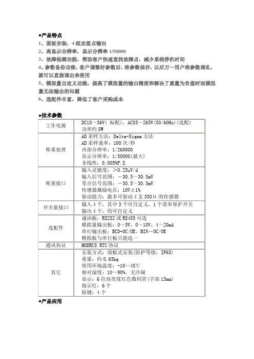
开关量输出的可见光传感器On9668
- 格式:pdf
- 大小:186.19 KB
- 文档页数:7
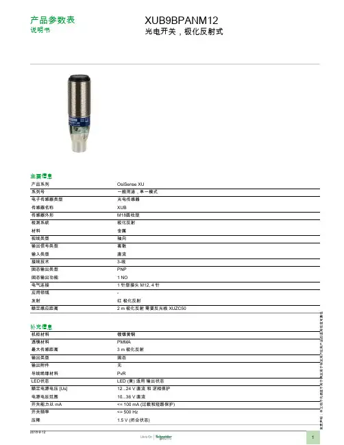
责声明:本文档不代表或不用于确定用于特定用户应用产品的适用性或可靠性产品参数表说明书XUB9BPANM12光电开关,极化反射式主要信息产品系列OsiSense XU 系列号一般用途,单一模式电子传感器类型光电传感器传感器名称XUB 传感器外形M18圆柱型检测系统极化反射材料金属视线类型轴向输出信号类型离散输入类型直流接线技术3-线固态输出类型PNP 固态输出功能 1 NO电气连接 1 针型接头 M12, 4 针应用领域-发射红 极化反射额定感应距离2 m 极化反射 需要反光板 XUZC50补充信息机柜材料镀镍黄铜透镜材料PMMA 最大传感距离 3 m 极化反射输出类型固态输出附件无导线绝缘材料PvRLED状态LED (黄) 适用 输出状态额定电源电压 [Us]12...24 V 直流 和 逆相保护电源电压范围10...36 V 直流开关能力以 mA <= 100 mA (过载和短路保护)开关频率<= 500 Hz 压降1.5 V (闭合状态)电流消耗35 mA (无负荷)启动延迟< 15 ms响应延迟< 1 ms复位延迟< 1 ms设置不带灵敏度调节直径18 mm长度62 mm产品重量0.05 kg环境产品认证CECSAUL环境温度-25...55 °C贮存环境温度-40...70 °C抗振动7 gn, 振幅 = +/- 1.5 mm (f = 10...55 Hz) 符合 IEC 60068-2-6抗冲击30 gn (持续时间 = 11 ms) 符合 IEC 60068-2-27IP 保护等级IP65 双重绝缘 符合 IEC 60529IP67 双重绝缘 符合 IEC 60529IP69K 双重绝缘 符合 DIN 40050可持续性RoHS法规(日期代码:YYWW)符合 - 自从 2009年第01周 - Schneider Electric declaration of conformitySchneider Electric declaration of conformityREACh法规有毒有害物质含量均在REACH规定的范围之内有毒有害物质含量均在REACH规定的范围之内合同保修阶段18 个月尺寸图尺寸接线接线图M12 连接器1:(+)3:(-)4:OUT/输出PNP 输出性能曲线检测曲线(Y)光束直径带反光板 XUZC50。

PD606E 安装式数字显示三相多功能仪表使用说明书符合标准:GB/T 22264安装、使用产品前,请仔细阅读使用说明书并妥善保管、备用目录一、产品简介 (01)二、功能介绍 (02)三、技术参数 (03)四、安装与接线 (04)五、编程操作 (08)六、面板说明与测量信息显示 (11)七、通讯规约 (30)八、功能输出 (43)九、常见问题及解决办法 (47)十、运输、贮存 (49)十一、公司承诺 (49)一、产品简介1.1引用标准执行标准:GB/T22264.1 安装式数字显示电测量仪表第1部分:定义和通用要求GB/T22264.2 安装式数字显示电测量仪表第2部分:电流表和电压表的特殊要求GB/T22264.3 安装式数字显示电测量仪表第3部分:有功功率表和无功功率表的特殊要求GB/T22264.4 安装式数字显示电测量仪表第4部分:频率表的特殊要求GB/T22264.5 安装式数字显示电测量仪表第5部分:相位表和功率因数表的特殊要求GB/T22264.7 安装式数字显示电测量仪表第7部分:多功能仪表的特殊要求GB/T22264.8 安装式数字显示电测量仪表第8部分:试验方法参考标准:GB/T 17215.321-2021电测量设备(交流)特殊要求第21部分:静止式有功电能表 (A级、B级、C级、D级和E级)GB/T 17215.323-2008 交流电测量设备特殊要求第23部分:静止式无功电能表(2级和3级)GB/T 17215.301-2007多功能电能表特殊要求1.2产品概述多功能网络电力仪表是针对电力系统、工矿企业、公共设施、智能大厦等场合的电力智能监控和电能计量需求而设计,能够高精度测量三相电网中的所有常用电力参数:三相电压、三相电流、有功功率、无功功率、视在功率、频率、功率因数等,并带有485通讯、电能脉冲输出等功能。
多功能网络电力仪表具有极高的性价比,可以取代测量指示仪表、电能计量仪表以及相关的辅助单元。
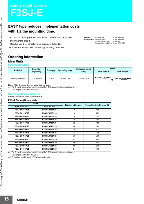
EASY type reduces implementation costs with 1/2 the mounting time.•In pursuit of simple functions: Upon detection of personnel, the machine stops.•Can be used for simple hand intrusion detection.•Implementation costs can be significantly reduced.Ordering InformationMain UnitsSafety Light CurtainNote:F3SJ-E uses a 3 m prewired discrete cable.*1.For S-mark compatible model, the suffix "-S" is added to the model name.(Example) F3SJ-E0185P25-SSafety Light Curtain Model ListPlease contact our sales representative.F3SJ-E Series (20 mm pitch)*1.For S-mark compatible model, the suffix "-S" is added to the model name.(Example) F3SJ-E0185P25-S*2.Protective height (mm) = Total sensor length RelatedinformationDimensions: Page 54 to 60Function List: Page 96 to 97Safety Precautions: Page 98Precautions on Safety: Page 99 to 104Application DetectioncapabilityBeam gap Operating rangeProtective height(mm)ModelPNP output NPN outputHand protection Dia. 25 mm20 mm0.2 to 7 m185 to 1,105F3SJ-E@@@@P25*1F3SJ-E@@@@N25ModelNumber of beams Protective height [mm] *2 PNP output *1NPN outputF3SJ-E0185P25F3SJ-E0185N258185F3SJ-E0225P25F3SJ-E0225N2510225F3SJ-E0305P25F3SJ-E0305N2514305F3SJ-E0385P25F3SJ-E0385N2518385F3SJ-E0465P25F3SJ-E0465N2522465F3SJ-E0545P25F3SJ-E0545N2526545F3SJ-E0625P25F3SJ-E0625N2530625F3SJ-E0705P25F3SJ-E0705N2534705F3SJ-E0785P25F3SJ-E0785N2538785F3SJ-E0865P25F3SJ-E0865N2542865F3SJ-E0945P25F3SJ-E0945N2546945F3SJ-E1025P25F3SJ-E1025N25501,025F3SJ-E1105P25F3SJ-E1105N25541,105CourtesyofCMA/Flodyne/Hydradyne▪MotionControl▪Hydraulic▪Pneumatic▪Electrical▪Mechanical▪(8)426-548▪www.cmafh.com16F3SJ-E17Accessories (Sold separately)Relays with Forcibly Guided ContactsLaser PointerSpatter Protection Cover (2 cables per set, common for emitter/receiver)Protective BarNote:The following are not provided with the Protective Bars.•Safety Light Curtain•Safety Light Curtain Top/Bottom Brackets •Wall Mounting Screw Unit*1.The same four digits indicating protective height that are used in the Sensor model number (@@@@) are used in the part of the Protectormodel number.*2.Purchase the F39-PB @@@@ (which contains two sets of brackets) to use Protective Bars for both the Emitter and Receiver.TypeAppearanceSpecificationsModel RemarksG7SA Relays withForcibly Guided Contacts•Nodes: 4•Contact type: 2A2B •Rated switch load:250 VAC 6A, 30 VDC 6A G7SA-2A2BFor details on other models or socket models, refer to the OMRON's website.•Nodes: 4•Contact type: 3NO+1NC •Rated switch load:250 VAC 6A, 30 VDC 6A G7SA-3A1BG7S-@-E Relays with Forcibly Guided Contacts•Nodes: 6•Contact type: 4NO+2NC •Rated switch load:250 VAC 10 A, 30 VDC 10 A G7S-4A2B-EFor details on other models or socket models, refer to the OMRON's website.•Nodes: 6•Contact type: 3NO+3NC •Rated switch load:250 VAC 10 A, 30 VDC 10 AG7S-3A3B-EAppearanceOutputModelLaser Pointer for F3SJ F39-PTJAppearanceModelRemarksF39-PB @@@@ *1• 2 Light Curtain brackets • 4 mounting brackets•0 to 4 intermediate brackets for backside mounting (quantity required for the sensing width)•0 to 4 intermediate brackets for mounting to the sides (quantity required for the sensing width)F39-PB @@@@-S *1 *2• 1 Light Curtain bracket • 2 mounting brackets•0 to 2 intermediate brackets for backside mounting (quantity required for the sensing width)•0 to 2 intermediate brackets for mounting to the sides (quantity required for the sensing width)C o u r t e s y o f C M A /F l o d y n e /H y d r a d y n e ▪ M o t i o n C o n t r o l ▪ H y d r a u l i c ▪ P n e u m a t i c ▪ E l e c t r i c a l ▪ M e c h a n i c a l ▪ (800) 426-5480 ▪ w w w .c m a f h .c o mF3SJ-E18Mirrors (12% Operating Range Attenuation)Sensor Mounting Bracket (Sold separately)Note:All the sensor mounting brackets for F3SJ-E are sold separately.*1.Combining F39-LJB2 and F39-LJB3-M6K makes F39-LJB3-M6.*2.Combining F39-LJB2 and F39-LJB3-M8K makes F39-LJB3-M8.Mirror materialWidth (mm)Thickness (mm)Length (mm)Model Glass mirror14532406F39-MLG0406610F39-MLG0610711F39-MLG0711914F39-MLG09141,067F39-MLG10671,219F39-MLG12191,422F39-MLG14221,626F39-MLG16261,830F39-MLG18302,134F39-MLG2134AppearanceSpecificationsModelApplicationRemarksTop/bottom bracket F39-LJB1Top/bottom bracket for F3SJ-E/B2 for an emitter,2 for a receiver,total of 4 per setIntermediate bracket F39-LJB2 *1 *2In combination use with top/bottom bracket for F3SJ-E/BCan be used as free-location bracket.1 set with2 piecesQuick mount bracketF39-LJB3-M6 *1Quick mount bracket for F3SJ-E/B Supports M6 slide nut for aluminum frame.1 set with2 piecesF39-LJB3-M8 *2Quick mount bracket for F3SJ-E/B Supports M8 slide nut for aluminum frame.Quick mount M6 bracketQuick mount M8 bracketF39-LJB3-M6K *1Bracket to mount an intermediate bracket to the aluminum frame witha single touch.Hexagon socket head cap screws (M6 x 10) are included.F39-LJB3-M8K *2Hexagon socket head cap screws (M8 x 14) are included.Compatible mounting bracketF39-LJB4Mounting bracket used when replacing existing area sensors (F3SJ-A or F3SN) with the F3SJ-E/B. 2 for an emitter,2 for a receiver,total of 4 per setContact mount bracket F39-LJB5Bracket to closely contact the backside of the Sensor.2 for an emitter,2 for a receiver,total of 4 per setC o u r t e s y o f C M A /F l o d y n e /H y d r a d y n e ▪ M o t i o n C o n t r o l ▪ H y d r a u l i c ▪ P n e u m a t i c ▪ E l e c t r i c a l ▪ M e c h a n i c a l ▪ (800) 426-5480 ▪ w w w .c m a f h .c o mF3SJ-E19Specifications (For details, refer to the instruction manual or User's manual.)Main UnitsF3SJ-E @@@@P25/N25*1.Do not use the Support Software and Setting Console for F3SJ-A. Operation cannot be guaranteed.*e of the Spatter Protection Cover causes a 10% maximum sensing distance attenuation.*3.The load inductance is the maximum value when the safety output frequently repeats ON and OFF. When you use the safety output at 4 Hz or less, the usable loadinductance becomes larger.*4.These values must be taken into consideration when connecting elements including a capacitive load such as capacitor.*5.The Vs indicates a voltage value in your environment.*6.To extend a cable of the F3SJ-E, refer to the User's Manual (SCHG-733/732).*7.Mounting brackets are sold separately.ModelPNP output F3SJ-E @@@@P25NPN outputF3SJ-E @@@@N 25Sensor typeType 4 safety light curtainSetting tool connection *1Parameter settings: Not availableSafety category Safety purpose of category 4, 3, 2, 1, or B Detection capability Opaque objects 25 mm in diameter Beam gap (P)20 mm Number of beams (n) 8 to 54Protective height (PH)185 to 1,105 mm Lens diameterDiameter 5 mm Operating range *20.2 to 7 m Response time (under stable lightincident condition) ON to OFF 15 ms max.OFF to ON 70 ms max.Startup waiting time2 s max.Power supply voltage (Vs)SELV/PELV 24 VDC±20% (ripple p-p 10% max.)Consumption current (no load)PNP output Emitter : Up to 22 beams: 41 mA max., 26 to 42 beams: 57 mA max., 46 to 54 beams: 63 mA max.Receiver : Up to 22 beams: 42 mA max., 26 to 42 beams: 47 mA max., 46 to 54 beams: 51 mA max.NPN output Emitter : Up to 22 beams: 41 mA max., 26 to 42 beams: 57 mA max., 46 to 54 beams: 63 mA max.Receiver : Up to 22 beams: 40 mA max., 26 to 42 beams: 45 mA max., 46 to 54 beams: 48 mA max.Light source (emitted wavelength)Infrared LED (870 nm)Effective aperture angle (EAA)Based on IEC 61496-2. Within ±2.5° for both emitter and receiver when the detection distance is 3 m or overSafety outputs (OSSD)PNP output Two PNP transistor outputs, load current 200 mA max., residual voltage 2 V max. (except for voltage drop due to cable extension), Leakage current 1 mA max., load inductance 2.2 H max. *3, Maximum capacity load 1 μF *4NPN outputTwo NPN transistor outputs, load current 200 mA max., residual voltage 2 V max. (except for voltage drop due to cable extension), Leakage current 1 mA max., load inductance 2.2 H max. *3, Maximum capacity load 1 μF *4Output operation modeSafety output: On when receiving lightInput voltagePNP outputON voltage: Vs-3 V to Vs OFF voltage: 0 V to 1/2 Vs or open *5NPN outputON voltage: 0 V to 3 V OFF voltage: 1/2 Vs to Vs or open *5Mutual interferenceprevention functionMutual interference prevention algorithm prevents interference in up to 3 sets.Test function •Self test (at power-ON and at power distribution)•External test (emission stop function by test input)Protection circuit Output short-circuit protection, and power supply reverse polarity protection Ambient temperature Operating: -10 to 55°C (non-freezing), Storage: -25 to 70°C Ambient humidity Operating: 35% to 85% (no condensation), Storage: 35% to 95% RH Operating ambient light intensity Incandescent lamp: 3,000 lx max., Sunlight: 10,000 lx max.Insulation resistance 20 M Ω min. (at 500 VDC)Dielectric strength 1,000 VAC 50/60 Hz, 1 min Degree of protection IP65 (IEC 60529)Vibration resistance Malfunction: 10 to 55 Hz, Multiple amplitude of 0.7 mm, 20 sweeps in X, Y, and Z directions Shock resistance Malfunction: 100 m/s 2, 1,000 times each in X, Y, and Z directions Pollution degree Pollution degree 3 (IEC 60664-1)Power cable Connection method: Pull-out type, cable length 3 m Number of wires: Emitter: 5 wires, receiver: 6 wiresCable diameter: Dia. 6 mmAllowable bending radius: R5 mmExtension cable 30 m max. *6MaterialCase: AluminumCap: ABS resin, PBTOptical cover: PMMA resin (acrylic)Cable: Oil resistant PVCWeight (packed state)Weight (g) = (protective height) x 2.6 + 800Accessories Test rod, Instruction Manual, User's Manual (CD-ROM) *7Applicable standards IEC 61496-1, EN 61496-1, UL 61496-1, Type 4 ESPE (Electro-Sensitive Protective Equipment)IEC 61496-2, CLC/TS 61496-2, UL 61496-2, Type 4 AOPD (Active Opto-electronic Protective Devices)IEC 61508-1 to -3, EN 61508-1 to -3 SIL3ISO 13849-1: 2006, EN ISO 13849-1: 2008 (PLe/Safety Category 4)UL 508, UL 1998, CAN/CSA C22.2 No.14, CAN/CSA C22.2 No.0.8C o u r t e s y o f C M A /F l o d y n e /H y d r a d y n e ▪ M o t i o n C o n t r o l ▪ H y d r a u l i c ▪ P n e u m a t i c ▪ E l e c t r i c a l ▪ M e c h a n i c a l ▪ (800) 426-5480 ▪ w w w .c m a f h .c o mF3SJ-E20IndicatorEmitterReceiverAccessoriesLaser Pointer*Battery life varies depending on a battery used.Name of indicator Label ONBlinking Top-beam-state indicator TOP Turns ON when the top beam is receiving light.---Stable-state indicator STB Turns ON when incidence level is more than 170% of the output ON threshold.Blinks when the safety output is turned OFF due to disturbance light or vibration.ON/OFF-state indicator ON OFF Green: Turns ON when safety output is ON.Red: Turns OFF when safety output is OFF.Red: Blinks when the F3SJ-E enters a lockout due to a safety output error.Lockout indicator LOCKOUT Turns ON when the F3SJ-E enters a lockout on the receiver.Blinks when the F3SJ-E enters a lockout on the emitter.Power indicator POWER Turns ON while the power of the emitter is ON.Blinks when the F3SJ-E enters a lockout due to power voltage/noise.Test indicatorTEST ---Blinks when external test is being performed.Bottom-beam-state indicatorBTMTurns ON when the bottom beam is receiving light.---Name of indicator Label ONBlinking Top-beam-state indicator TOP Turns ON when the top beam is receiving light.---Stable-state indicator STB Turns ON when incidence level is more than 170% of the output ON threshold.Blinks when the safety output is turned OFF due to disturbance light or vibration.ON/OFF-state indicator ON OFF Green: Turns ON when safety output is ON.Red: Turns OFF when safety output is OFF.Red: Blinks when the F3SJ-E enters a lockout due to a safety output error.Lockout indicator LOCKOUT Turns ON when the F3SJ-E enters a lockout on the emitter.Blinks when the F3SJ-E enters a lockout on the receiver.Communication indicatorCOMTurns ON when communication between emitter and receiver is established.Blinks when the F3SJ-E enters lockout due to a communication error between receiver and emitter.Configuration indicator CFG ---Blinks when the F3SJ-E enters lockout due to a model type error between receiver and emitter.Internal error indicator INTERNAL ---Blinks when the F3SJ-E enters a lockout due to an internal error.Bottom-beam-state indicatorBTMTurns ON when the bottom beam is receiving light.---ItemModelF39-PTJApplicable sensor F3SJ Series Power supply voltage 4.65 or 4.5 VDCBattery Three button batteries (SR44 or LR44)Battery life *SR44: 10 hours of continuous operation, LR44: 6 hours of continuous operationLight sourceRed semiconductor laser (wavelength: 650 nm, 1 mW max. JIS class 2, EN/IEC class 2, FDA class II)Spot diameter (typical value) 6.5 mm at 10 mAmbient temperature Operating: 0 to 40°C Storage: -15 to 60°C (with no icing or condensation)Ambient humidity Operating and storage: 35% to 85% (with no condensation)Material Laser module case: aluminum Mounting bracket: aluminum and stainless Weight Approx. 220 g (packed)AccessoriesLaser safety standard labels (EN: 1, FDA: 3) Button batteries (SR44: 3), instruction manualC o u r t e s y o f C M A /F l o d y n e /H y d r a d y n e ▪ M o t i o n C o n t r o l ▪ H y d r a u l i c ▪ P n e u m a t i c ▪ E l e c t r i c a l ▪ M e c h a n i c a l ▪ (800) 426-5480 ▪ w w w .c m a f h .c o mF3SJ-E21ConnectionsBasic Wiring DiagramMinimum wiring required to check the operation of the F3SJ-E [PNP Output]Minimum wiring required to check the operation of the F3SJ-E [NPN Output]Note:This circuit diagram is used for operation check.For an actual circuit example, refer to page 23.Note:This circuit diagram is used for operation check.For an actual circuit example, refer to page 23.C o u r t e s y o f C M A /F l o d y n e /H y d r a d y n e ▪ M o t i o n C o n t r o l ▪ H y d r a u l i c ▪ P n e u m a t i c ▪ E l e c t r i c a l ▪ M e c h a n i c a l ▪ (800) 426-5480 ▪ w w w .c m a f h .c o mF3SJ-E22Input/Output Circuit Diagram+24 VDC 0 V<Input Circuit (Test Input)>+24 VDC0 V<Input Circuit (Test Input)>Entire Circuit DiagramInput circuit diagram by function[PNP Output][NPN Output]Entire Circuit DiagramInput circuit diagram by functionC o u r t e s y o f C M A /F l o d y n e /H y d r a d y n e ▪ M o t i o n C o n t r o l ▪ H y d r a u l i c ▪ P n e u m a t i c ▪ E l e c t r i c a l ▪ M e c h a n i c a l ▪ (800) 426-5480 ▪ w w w .c m a f h .c o mF3SJ-E23Connection Circuit ExamplesWiring for single F3SJ-E application Note:The above PL is only the evaluation result of the example. The PL must be evaluated in an actual application by the customer after confirmingthe usage conditions.z Application Overview•The power supply to the motor M is turned OFF when the beam is blocked.•The power supply to the motor M is kept OFF until the beams are unblocked and the reset switch S2 is pressed.PL/safety category ModelStop categoryResetPLe/4 equivalentSafety Light Curtain F3SJ-E @@@@P25Safety Relay G7SAManual[PNP Output]S1S2K1, K2, K3KM1, KM2M : External test/lockout reset switch (connect to 0 V if a switch is not required): Reset switch: Safety relay with force-guided contact (G7SA): Safety relay with force-guided contact (G7SA) or magnetic contactor : 3-phase motorUnblocked BlockedReset switch(S2)Safety output K3 N.C. contactK3 N.O. contact K1,K2 N.C. contact K1,K2 N.O. contact KM1,KM2 N.C. contact KM1,KM2 N.O. contactC o u r t e s y o f C M A /F l o d y n e /H y d r a d y n e ▪ M o t i o n C o n t r o l ▪ H y d r a u l i c ▪ P n e u m a t i c ▪ E l e c t r i c a l ▪ M e c h a n i c a l ▪ (800) 426-5480 ▪ w w w .c m a f h .c o mF3SJ-E24Wiring for single F3SJ-E application Note:The above PL is only the evaluation result of the example. The PL must be evaluated in an actual application by the customer after confirmingthe usage conditions.z Application Overview•The power supply to the motor M is turned OFF when the beam is blocked.•The power supply to the motor M is kept OFF until the beams are unblocked and the reset switch S2 is pressed.PL/safety category ModelStop categoryResetPLe/4 equivalentSafety Light Curtain F3SJ-E @@@@N25Safety Relay G7SAManual[NPN Output]S1S2K1, K2, K3KM1, KM2M: External test/lockout reset switch (connect to 24 V if a switch is not required): Reset switch: Safety relay with force-guided contact (G7SA): Safety relay with force-guided contact (G7SA) or magnetic contactor : 3-phase motorKM1,KM2 N.C. contact K3 N.C. contact Unblocked Blocked Reset switch(S2)External test/lockout reset switch(S1)Safety output K1,K2 N.O. contact KM1,KM2 N.O. contactK1,K2 N.C. contact K3 N.O. contact C o u r t e s y o f C M A /F l o d y n e /H y d r a d y n e ▪ M o t i o n C o n t r o l ▪ H y d r a u l i c ▪ P n e u m a t i c ▪ E l e c t r i c a l ▪ M e c h a n i c a l ▪ (800) 426-5480 ▪ w w w .c m a f h .c o mF3SJ-E25Wiring to connect a F3SJ-E with a controller G9SP Note:The above PL is only the evaluation result of the example. The PL must be evaluated in an actual application by the customer after confirmingthe usage conditions.z Application Overview•The power supply to the motor M is turned OFF when the beam is blocked.•The power supply to the motor M is turned OFF when the emergency stop switch is pressed.•The power supply to the motor M is kept OFF until the beams are unblocked and the reset switch S2 is pressed while the emer-gency stop switch is released.PL/safety category ModelStop categoryResetPLe/4 equivalentSafety Light Curtain F3SJ-E @@@@P25Safety Controller G9SP Safety Relay G7SAEmergency Stop Switch A165E/A22EManual[PNP Output]C o u r t e s y o f C M A /F l o d y n e /H y d r a d y n e ▪ M o t i o n C o n t r o l ▪ H y d r a u l i c ▪ P n e u m a t i c ▪ E l e c t r i c a l ▪ M e c h a n i c a l ▪ (800) 426-5480 ▪ w w w .c m a f h .c o mF3SJ-E26Wiring to connect a F3SJ-E with a controller G9SA-301 Note:The above PL is only the evaluation result of the example. The PL must be evaluated in an actual application by the customer after confirmingthe usage conditions.z Application Overview•The power supply to the motor M is turned OFF when the beam is blocked.•The power supply to the motor M is turned OFF when the emergency stop switch is pressed.•The power supply to the motor M is kept OFF until the beams are unblocked and the reset switch S2 is pressed while the emer-gency stop switch is released.PL/safety category ModelStop categoryResetPLe/4 equivalentSafety Light Curtain F3SJ-E @@@@P25Safety Relay Unit G9SA-301 24V AC/DC Safety Relay G7SAEmergency Stop Switch A165E/A22EManual[PNP Output]* If an emergency stop switch is not used, connect safety output 1 to T12 terminal and safety output 2 to T23 directly.S1: External test/lockout reset switch (connect to 0 V if a switch is not required)S2: Interlock reset switchS3: Emergency stop switch (force-opening contact) (A165E, A22E)KM1,KM2: Safety relay with force-guided contact (G7SA) or magnetic contactor M: 3-phase motorUnblocked BlockedExternal test/lockout reset switch(S1)Interlock reset switch(S2)Emergency stop switch(S3)Safety output K1,K2 N.O. contact KM1,KM2 N.O. contactK1,K2 N.C. contact KM1,KM2 N.C. contactC o u r t e s y o f C M A /F l o d y n e /H y d r a d y n e ▪ M o t i o n C o n t r o l ▪ H y d r a u l i c ▪ P n e u m a t i c ▪ E l e c t r i c a l ▪ M e c h a n i c a l ▪ (800) 426-5480 ▪ w w w .c m a f h .c o mF3SJ-E27Wiring to connect a F3SJ-E with a controller G9SA-301-P Note:The above PL is only the evaluation result of the example. The PL must be evaluated in an actual application by the customer after confirmingthe usage conditions.z Application Overview•The power supply to the motor M is turned OFF when the beam is blocked.•The power supply to the motor M is turned OFF when the emergency stop switch is pressed.•The power supply to the motor M is kept OFF until the beams are unblocked and the reset switch S2 is pressed while the emer-gency stop switch is released.Note:1.As the G9SP Safety Controller is a PNP output type, it cannot be connected to the F3SJ-E @@@@N25. Also, a Safety Controller with PNPoutput cannot be connected to the F3SJ-E @@@@N25.2.The G9SA-301-P is a safety relay unit only for NPN output.PL/safety category ModelStop categoryResetPLe/4 equivalentSafety Light Curtain F3SJ-E @@@@N25Safety Relay Unit G9SA-301-P 24V DC Safety Relay G7SAEmergency Stop Switch A165E/A22EManual[NPN Output]MKM1KM2* If an emergency stop s w itch is not u sed, connect safety o u tp u t 1 to T12 terminal and safety o u tp u t 2 to T23 directly.S1: External test/ locko u t reset s w itch(connect to 24 V if a s w itch is not re qu ired)S2 : Interlock reset s w itch S3 : Emergency stop s w itch (force-opening contact) (A165E, A22E)KM1, KM2 : Safety relay w ith force-g u ided contact (G7SA) or magnetic contactor M : 3-phase motorUn b lockedBlockedExternal test/locko u t reset s w itch(S1)Interlock reset s w itch(S2)Emergency stop s w itch(S3)Safety o u tp u t K1,K2 N .O. contactKM1,KM2 N .O. contact K1,K2 N .C. contact KM1,KM2 N .C. contactC o u r t e s y o f C M A /F l o d y n e /H y d r a d y n e ▪ M o t i o n C o n t r o l ▪ H y d r a u l i c ▪ P n e u m a t i c ▪ E l e c t r i c a l ▪ M e c h a n i c a l ▪ (800) 426-5480 ▪ w w w .c m a f h .c o m。
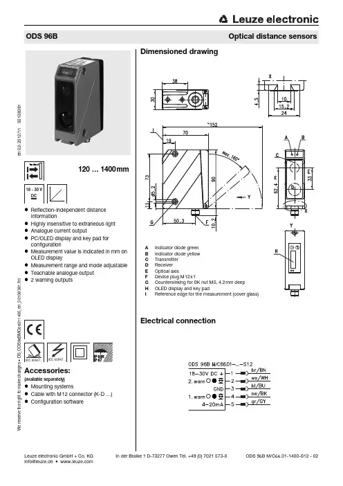
Leuze electronic GmbH + Co. KG In der Braike 1 D-73277 Owen Tel. +49 (0) 7021 573-0*************•W e r e s e r v e t h e r i g h t t o m a k e c h a n g e s • D S _O D S 96B M C 66011400_e n _50108381.f m●Reflection-independent distance information●Highly insensitive to extraneous light ●Analogue current output●PC/OLED display and key pad for configuration●Measurement value is indicated in mm on OLED display●Measurement range and mode adjustable ●Teachable analogue output ●2 warning outputs120…1400mm18 - 30 VDCAccessories:(available separately)●Mounting systems●Cable with M12 connector (K-D …)●Configuration softwareDimensioned drawingA Indicator diode greenB Indicator diode yellowC TransmitterD ReceiverE Optical axisF Device plug M12x1G Countersinking for SK nut M5, 4.2mm deep H OLED display and key padI Reference edge for the measurement (cover glass)Electrical connectionODS 96BOptical distance sensorsODS 96B M/C66.01-1400-S12 - 02e n 02-2012/1150108381ODS 96B M/C66.01-1400-S12 - 022012/11SpecificationsOptical dataMeasurement range 1)1)Luminosity coefficient 6%…90%, complete measurement range, at 20°C, medium range of U B , measurement object ≥50x50mm²120…1400mm Resolution 2)2)Minimum and maximum value depend on measurement distance0.1…0.5mm Light source LEDWavelength 880nm (infrared light)Light spotapprox. 15 x 15mm 2 at 600mmError limits (relative to measurement distance)Absolute measurement accuracy 1)±1.5% up to 800mm, ±2% up to 1400mm Repeatability 3)3)Same object, identical environmental conditions, measurement object ≥50x50mm²±0.5% up to 800mm, ±1% up to 1400mm b/w detect. thresholds (6…90% rem.)≤1% up to 800mm, ≤2% up to 1400mm Temperature compensationyes 4)4)Typ. ± 0.02 %/KTimingMeasurement time 1…51)ms Response time 1)≤15ms Delay before start-up≤300msElectrical dataOperating voltage U B 18…30VDC (incl. residual ripple)Residual ripple≤15% of U B Open-circuit current ≤150mASwitching output 2 push-pull warning outputs 5),PNP light switching, NPN dark switching, respectively 5)The push-pull switching outputs must not be connected in parallelSignal voltage high/low ≥(U B -2V)/≤2VAnalogue outputcurrent 4…20mA, R L ≤500ΩIndicatorsteach-in on GNDteach-in on +U BGreen LED continuous lightready flashing fault teaching procedure offno voltageYellow LED continuous lightobject inside teach-in measurement distanceflashing teaching procedureoffobject outside teach-in measurement distanceMechanical dataMetal housingHousing diecast zinc Optics cover glassWeight 380g Connection type M12 connector Environmental dataAmbient temp. (operation/storage)-20°C …+50°C / -30°C …+70°C Protective circuit 6)6)1=transient protection, 2=polarity reversal protection, 3=short circuit protection for all outputs 1,2,3VDE safety class 7)7)Rating voltage 250VAC, with cover closedII, all-insulated Protection class IP 67, IP 69K 8)8)IP 69K test acc. to DIN 40050 part 9 simulated, high pressure cleaning conditions without the use of additives.Acids and bases are not part of the test.LED class1 (acc. to EN 60825-1)Standards appliedIEC 60947-5-2A Area not definedB Linearity not definedC Measurement rangeD Object presentE No object detected FMeasurement distanceOrder guideDesignationPart No.With M12 connector Current outputODS 96B M/C66.01-1400-S1250106727TablesDiagramsODS 96BRemarks●Measurement timedepends on the reflectivity of the measurement object and on the mea-surement mode.●Coding of the warning outputs:●Approved purpose : The ODS 96B distance sensors are optical elec-tronic sensors for the opti-cal, contactless measure-ment of distance to objects.Warning outputMeaning1200Distance measurement is impossible01Object below measure-ment range (short range)10Object beyond the mea-surement range (distant range)11Optimum function。


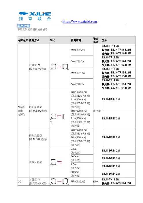
E3JK种类:不带支架或反射板的传感器电源电压检测方式形状检测距离输出形式型号AC/DC 自由电源型对射型*1(投光器+受光器)40m(红色光)继电器E3JK-TR11 2M投光器: E3JK-TR11-L 2M受光器: E3JK-TR11-D 2M5m(红色光)E3JK-TR12 2M投光器: E3JK-TR12-L 2M受光器: E3JK-TR12-D 2M40m(红外线)E3JK-TR13 2M投光器: E3JK-TR13-L 2M受光器: E3JK-TR13-D 2M5m(红外线)E3JK-TR14 2M投光器: E3JK-TR14-L 2M受光器: E3JK-TR14-D 2M回归反射型(无M.S.R.功能)*27m[100mm]*3(使用E39-R1时)11m[100mm](使用E39-R2时)(红色光)E3JK-RR11 2M7m[100mm]*3(使用E39-R1时)11m[100mm](使用E39-R2时)(红外线)E3JK-RR13 2M回归反射型(带M.S.R.功能)6m[100mm]*3(使用E39-R1时)10m[100mm](使用E39-R2时)(红色光)E3JK-RR12 2M扩散反射型2.5m(红色光)E3JK-DR11 2M300mm(红色光)E3JK-DR12 2M2.5m(红外线)E3JK-DR13 2M300mm(红外线)E3JK-DR14 2MDC 对射型*1(投光器+受光器)40m(红色光) NPNE3JK-TN11 2M投光器: E3JK-TN11-L 2M受光器: E3JK-TN11-D 2MPNP E3JK-TP11 2M投光器: E3JK-TP11-L 2M 受光器: E3JK-TP11-D 2M5m(红色光) NPNE3JK-TN12 2M投光器: E3JK-TN12-L 2M受光器: E3JK-TN12-D 2M PNPE3JK-TP12 2M投光器: E3JK-TP12-L 2M受光器: E3JK-TP12-D 2M40m(红外线) NPNE3JK-TN13 2M投光器: E3JK-TN13-L 2M受光器: E3JK-TN13-D 2M PNPE3JK-TP13 2M投光器: E3JK-TP13-L 2M受光器: E3JK-TP13-D 2M5m(红外线) NPNE3JK-TN14 2M投光器: E3JK-TN14-L 2M受光器: E3JK-TN14-D 2M PNPE3JK-TP14 2M投光器: E3JK-TP14-L 2M受光器: E3JK-TP14-D 2M回归反射型(无M.S.R.功能)*2 7m[100mm]*3(使用E39-R1时)11m[100mm](使用E39-R2时)(红色光)NPN E3JK-RN11 2MPNP E3JK-RP11 2M7m[100mm]*3(使用E39-R1时)11m[100mm](使用E39-R2时)(红外线)NPN E3JK-RN13 2MPNP E3JK-RP13 2M回归反射型(带M.S.R.功能) 6m[100mm]*3(使用E39-R1时)10m[100mm](使用E39-R2时)(红色光)NPN E3JK-RN12 2MPNP E3JK-RP12 2M扩散反射型2.5m(红色光)NPN E3JK-DN11 2MPNP E3JK-DP11 2M 300mm(红色光)NPN E3JK-DN12 2MPNP E3JK-DP12 2M 2.5m NPN E3JK-DN13 2M(红外线) PNP E3JK-DP13 2M300mm (红外线) NPN E3JK-DN14 2M PNP E3JK-DP14 2M*1. 对射型的标准价格、标准库存为投光器和受光器配套的产品。

一概述⋯⋯⋯⋯⋯⋯⋯⋯⋯⋯⋯⋯⋯⋯⋯⋯⋯⋯⋯⋯⋯⋯⋯⋯⋯⋯⋯⋯⋯⋯1-1 二DPU简介⋯⋯⋯⋯⋯⋯⋯⋯⋯⋯⋯⋯⋯⋯⋯⋯⋯⋯⋯⋯⋯⋯⋯⋯⋯⋯⋯⋯1-1 三DPU组态过程⋯⋯⋯⋯⋯⋯⋯⋯⋯⋯⋯⋯⋯⋯⋯⋯⋯⋯⋯⋯⋯⋯⋯⋯⋯⋯1-2 四页⋯⋯⋯⋯⋯⋯⋯⋯⋯⋯⋯⋯⋯⋯⋯⋯⋯⋯⋯⋯⋯⋯⋯⋯⋯⋯⋯⋯⋯⋯⋯1-2 五功能块⋯⋯⋯⋯⋯⋯⋯⋯⋯⋯⋯⋯⋯⋯⋯⋯⋯⋯⋯⋯⋯⋯⋯⋯⋯⋯⋯⋯⋯1-2 1 XDPS实时网和硬件I/O功能块1.1 模拟量下网功能块 XNETAI ID=100⋯⋯⋯⋯⋯⋯⋯⋯⋯⋯⋯⋯⋯1-51.2 开关量下网功能块 XNETDI ID=101⋯⋯⋯⋯⋯⋯⋯⋯⋯⋯⋯⋯⋯1-51.3 模拟量上网功能块 XNETAO ID=102⋯⋯⋯⋯⋯⋯⋯⋯⋯⋯⋯⋯⋯1-51.4 开关量上网功能块 XNETDO ID=103⋯⋯⋯⋯⋯⋯⋯⋯⋯⋯⋯⋯⋯1-61.5 模拟量输入功能块 XAI ID=104⋯⋯⋯⋯⋯⋯⋯⋯⋯⋯⋯⋯⋯1-71.6 开关量输入功能块 XDI ID=105⋯⋯⋯⋯⋯⋯⋯⋯⋯⋯⋯⋯⋯1-81.7 模拟量输出功能块 XAO ID=106⋯⋯⋯⋯⋯⋯⋯⋯⋯⋯⋯⋯⋯1-81.8 开关量输出功能块 XDO ID=107⋯⋯⋯⋯⋯⋯⋯⋯⋯⋯⋯⋯⋯1-91.9 脉冲量输入功能块 XPI ID=108⋯⋯⋯⋯⋯⋯⋯⋯⋯⋯⋯⋯⋯1-91.10 页间模拟量输入功能块 PgAI ID=110⋯⋯⋯⋯⋯⋯⋯⋯⋯⋯⋯⋯⋯1-91.11 页间开关量输入功能块 PgDI ID=111⋯⋯⋯⋯⋯⋯⋯⋯⋯⋯⋯⋯⋯1-101.12 页间模拟量输出功能块 PgAO ID=112⋯⋯⋯⋯⋯⋯⋯⋯⋯⋯⋯⋯⋯1-101.13 页间开关量输处功能块 PgDO ID=113⋯⋯⋯⋯⋯⋯⋯⋯⋯⋯⋯⋯⋯1-102 模拟函数2.1 2输入加法器 ADD ID=1⋯⋯⋯⋯⋯⋯⋯⋯⋯⋯⋯⋯⋯⋯1-112.2 乘法器 MUL ID=2⋯⋯⋯⋯⋯⋯⋯⋯⋯⋯⋯⋯⋯⋯1-112.3 除法器 DIV ID=3⋯⋯⋯⋯⋯⋯⋯⋯⋯⋯⋯⋯⋯⋯1-112.4 开方器 SQRT ID=4⋯⋯⋯⋯⋯⋯⋯⋯⋯⋯⋯⋯⋯⋯1-122.5 取绝对值 ABS ID=5⋯⋯⋯⋯⋯⋯⋯⋯⋯⋯⋯⋯⋯⋯1-122.6 五次多项式 POLYNOM ID=6⋯⋯⋯⋯⋯⋯⋯⋯⋯⋯⋯⋯⋯⋯1-122.7 8输入数学统计器 SUM8 ID=7⋯⋯⋯⋯⋯⋯⋯⋯⋯⋯⋯⋯⋯⋯1-132.8 12段函数变换F(X) ID=8⋯⋯⋯⋯⋯⋯⋯⋯⋯⋯⋯⋯⋯⋯1-132.9 保留ID=9⋯⋯⋯⋯⋯⋯⋯⋯⋯⋯⋯⋯⋯⋯1-142.10 指数/对数函数POW/LOG ID=10⋯⋯⋯⋯⋯⋯⋯⋯⋯⋯⋯⋯⋯1-142.11 三角和反三角函数 TRIANGLE ID=11⋯⋯⋯⋯⋯⋯⋯⋯⋯⋯⋯⋯⋯1-142.12、热力性质计算 PTCAl ID=12⋯⋯⋯⋯⋯⋯⋯⋯⋯⋯⋯⋯⋯1-153 时间过程函数3.1 超前滞后模块 LEADLAG ID=20⋯⋯⋯⋯⋯⋯⋯⋯⋯⋯⋯⋯⋯1-163.2 滞后模块 DELAY ID=21⋯⋯⋯⋯⋯⋯⋯⋯⋯⋯⋯⋯⋯1-163.3 微分模块 DIFF ID=22⋯⋯⋯⋯⋯⋯⋯⋯⋯⋯⋯⋯⋯1-173.4 时域统计模块 TSUM ID=23⋯⋯⋯⋯⋯⋯⋯⋯⋯⋯⋯⋯⋯1-173.5 数字滤波 FILTER ID=24⋯⋯⋯⋯⋯⋯⋯⋯⋯⋯⋯⋯⋯1-183.6 斜坡信号发生器ID=25⋯⋯⋯⋯⋯⋯⋯⋯⋯⋯⋯⋯⋯1-183.7 段信号发生器f(t) ID=26⋯⋯⋯⋯⋯⋯⋯⋯⋯⋯⋯⋯⋯1-183.8 伪随机信号发生器 Undefined ID=27⋯⋯⋯⋯⋯⋯⋯⋯⋯⋯⋯⋯⋯1-193.9 时域开关量统计模块 TSUMD ID=28⋯⋯⋯⋯⋯⋯⋯⋯⋯⋯⋯⋯⋯1-194 控制用算法4.1 二选一选择器 TWOSEL ID=30⋯⋯⋯⋯⋯⋯⋯⋯⋯⋯⋯⋯⋯1-204.2 三选一选择器 THREESEL ID=31⋯⋯⋯⋯⋯⋯⋯⋯⋯⋯⋯⋯⋯1-204.3 无扰切换模块 SFT ID=32⋯⋯⋯⋯⋯⋯⋯⋯⋯⋯⋯⋯⋯1-214.4 高低限幅器 HLLMT ID=33⋯⋯⋯⋯⋯⋯⋯⋯⋯⋯⋯⋯⋯1-214.5 高低限报警 HLALM ID=34⋯⋯⋯⋯⋯⋯⋯⋯⋯⋯⋯⋯⋯1-214.6 速率限制器 RATLMT ID=35⋯⋯⋯⋯⋯⋯⋯⋯⋯⋯⋯⋯⋯1-224.7 速率报警器 RATALM ID=36⋯⋯⋯⋯⋯⋯⋯⋯⋯⋯⋯⋯⋯1-224.8 偏差运算 DEV ID=37⋯⋯⋯⋯⋯⋯⋯⋯⋯⋯⋯⋯⋯1-234.9 PID运算 EPID ID=38⋯⋯⋯⋯⋯⋯⋯⋯⋯⋯⋯⋯⋯1-244.10 简单PID模块 Undefined ID=39⋯⋯⋯⋯⋯⋯⋯⋯⋯⋯⋯⋯⋯1-244.11 2输出平衡模块 Balance2 ID=40⋯⋯⋯⋯⋯⋯⋯⋯⋯⋯⋯⋯⋯1-254.12 八输入平衡模块 BALANCE8 ID=41⋯⋯⋯⋯⋯⋯⋯⋯⋯⋯⋯⋯⋯1-264.13 数字驱动伺服模块 DDS ID=42⋯⋯⋯⋯⋯⋯⋯⋯⋯⋯⋯⋯⋯1-264.14 查表式模糊控制器 FTAB ID=43⋯⋯⋯⋯⋯⋯⋯⋯⋯⋯⋯⋯⋯1-274.15 慢信号保护模块 SAIPro ID=44⋯⋯⋯⋯⋯⋯⋯⋯⋯⋯⋯⋯⋯1-285 逻辑电路5.1 2输入与 AND ID=50⋯⋯⋯⋯⋯⋯⋯⋯⋯⋯⋯⋯⋯1-295.2 2输入或 OR ID=51⋯⋯⋯⋯⋯⋯⋯⋯⋯⋯⋯⋯⋯1-295.3 反相器 NOT ID=52⋯⋯⋯⋯⋯⋯⋯⋯⋯⋯⋯⋯⋯1-295.4 异或器 XOR ID=53⋯⋯⋯⋯⋯⋯⋯⋯⋯⋯⋯⋯⋯1-305.5 8输入数量或 QOR8 ID=54⋯⋯⋯⋯⋯⋯⋯⋯⋯⋯⋯⋯⋯1-305.6 RS触发器ID=55⋯⋯⋯⋯⋯⋯⋯⋯⋯⋯⋯⋯⋯1-305.7 定时器 TIMER ID=56⋯⋯⋯⋯⋯⋯⋯⋯⋯⋯⋯⋯⋯1-315.8 计数器 CNT ID=57⋯⋯⋯⋯⋯⋯⋯⋯⋯⋯⋯⋯⋯1-325.9 模拟比较器 CMP ID=58⋯⋯⋯⋯⋯⋯⋯⋯⋯⋯⋯⋯⋯1-335.10 循环定时器 CYCTIMER ID=59⋯⋯⋯⋯⋯⋯⋯⋯⋯⋯⋯⋯⋯1-335.11 步序控制器 STEP ID=60⋯⋯⋯⋯⋯⋯⋯⋯⋯⋯⋯⋯⋯1-345.12 软件脉冲列输出 SPO ID=61⋯⋯⋯⋯⋯⋯⋯⋯⋯⋯⋯⋯⋯1-356 操作器6.1 模拟软手操器 S/MA ID=70⋯⋯⋯⋯⋯⋯⋯⋯⋯⋯⋯⋯⋯1-366.2 键盘模拟量增减 KBML ID=71⋯⋯⋯⋯⋯⋯⋯⋯⋯⋯⋯⋯⋯1-376.3 数字手操器 DEVICE ID=72⋯⋯⋯⋯⋯⋯⋯⋯⋯⋯⋯⋯⋯1-376.4 简单数字手操器 D/MA ID=73⋯⋯⋯⋯⋯⋯⋯⋯⋯⋯⋯⋯⋯1-416.5 带开关输出的模拟软手操器ADS/MA ID=74⋯⋯⋯⋯⋯⋯⋯⋯1-416.6 电气数字手操器 EDEVICE ID=75⋯⋯⋯⋯⋯⋯⋯⋯⋯⋯⋯⋯⋯1-427 特殊功能块7.1 品质(状态)测试模块ID=80⋯⋯⋯⋯⋯⋯⋯⋯⋯⋯⋯⋯⋯1-447.2 触发执行事件 EVENT ID=81⋯⋯⋯⋯⋯⋯⋯⋯⋯⋯⋯⋯⋯1-447.3 16个布尔变量转换为长整形变量 B16TOL ID=82⋯⋯⋯⋯⋯⋯⋯⋯1-457.4 长整形变量转换为16位布尔个变量ID=83⋯⋯⋯⋯⋯⋯⋯⋯1-45 LTOB167.5 长整型模拟变量含义转换器 LTOF ID=84⋯⋯⋯⋯⋯⋯⋯⋯1-457.6 节点(状态)测试模块 TDPU ID=85⋯⋯⋯⋯⋯⋯⋯⋯⋯⋯⋯⋯⋯1-467.7 上网报警闭锁功能块 DisAlm ID=86⋯⋯⋯⋯⋯⋯⋯⋯⋯⋯⋯⋯⋯1-467.8 上网报警限修改功能块 ChgAlm ID=87⋯⋯⋯⋯⋯⋯⋯⋯1-467.9 I/O卡件测试模块 TCard ID=88⋯⋯⋯⋯⋯⋯⋯⋯⋯⋯⋯⋯⋯1-477.10 I/O站测试模块 TNode ID=89⋯⋯⋯⋯⋯⋯⋯⋯⋯⋯⋯⋯⋯1-47附录一 XDPS预定义标准功能块说明99.8.23一、概述XDPS的软件功能分DPU和MMI,MMI又包括OPU、ENG、HSU等,DPU又有VDPU、专用GTW 等。
Leuze electronic GmbH + Co. KG In der Braike 1 D-73277 Owen Tel. +49 (0) 7021 573-0*************•W e r e s e r v e t h e r i g h t t o m a k e c h a n g e s • D S _O D S R 96B M C V 6600_e n _50107947.f m●Reflection-independent distance information●Highly insensitive to extraneous light ●Analogue current or voltage output ●PC/OLED display and key pad for configuration●Measurement value is indicated in mm on OLED display●Measurement range and mode adjustable ●Teachable switching output and analogue output100…600mm18 - 30 VDCAccessories:(available separately)●Mounting systems●Cable with M12 connector (K-D …)●Configuration softwareDimensioned drawingA Indicator diode greenB Indicator diode yellowC TransmitterD ReceiverE Optical axisF Device plug M12x1G Countersinking for SK nut M5, 4.2mm deep H OLED display and key padI Reference edge for the measurement (cover glass)Electrical connectionODSR 96BOptical distance sensorsODSR 96B M/C6-600-S12 - 04ODSR 96B M/V6-600-S12 - 04e n 04-2012/1150107947ODSR 96B M/C6-600-S12 - 042012/11ODSR 96B M/V6-600-S12 - 04SpecificationsOptical dataMeasurement range 1)1)Luminosity coefficient 6%…90%, complete measurement range, at 20°C, medium range of U B , measurement object ≥50x50mm²100…600mm Resolution 2)2)Minimum and maximum value depend on measurement distance0.1…0.5mm Light source LEDWavelength 635nm (visible red light)Light spotapprox. 15 x 15mm 2 at 600mm Laser warning noticesee remarks Error limits (relative to measurement distance)Absolute measurement accuracy 1)±1.5%Repeatability 3)3)Same object, identical environmental conditions, measurement object ≥50x50mm²±0.5%b/w detect. thresholds (6…90% rem.)≤1%Temperature compensationyes 4)4)Typ. ± 0.02 %/KTimingMeasurement time 1…51)ms Response time 1)≤15ms Delay before start-up ≤300msElectrical dataOperating voltage U B 18…30VDC (incl. residual ripple)Residual ripple≤15% of U B Open-circuit current ≤150mASwitching output push-pull switching output 5),PNP light switching, NPN dark switching 5)The push-pull switching outputs must not be connected in parallelSignal voltage high/low ≥(U B -2V)/≤2VAnalogue outputvoltage 1…10V, R L ≥2k Ω current 4…20mA, R L ≤500ΩIndicatorsteach-in on GNDteach-in on +U BGreen LED continuous lightready flashing fault teaching procedure offno voltageYellow LED continuous lightobject inside teach-in measurement distanceflashing teaching procedureoffobject outside teach-in measurement distanceMechanical dataMetal housingHousing diecast zinc Optics cover glassWeight 380g Connection type M12 connector Environmental dataAmbient temp. (operation/storage)-20°C …+50°C / -30°C …+70°C Protective circuit 6)6)1=transient protection, 2=polarity reversal protection, 3=short circuit protection for all outputs 1,2,3VDE safety class 7)7)Rating voltage 250VAC, with cover closedII, all-insulated Protection class IP 67, IP 69K 8)8)IP 69K test acc. to DIN 40050 part 9 simulated, high pressure cleaning conditions without the use of additives.Acids and bases are not part of the test.LED class1 (acc. to EN 60825-1)Standards appliedIEC 60947-5-2A Area not definedB Linearity not definedC Measurement rangeD Object presentE No object detected FMeasurement distanceOrder guideDesignationPart No.With M12 connector Current output ODSR 96B M/C6-600-S1250106730Voltage outputODSR 96B M/V6-600-S1250106731TablesDiagramsODSR 96BRemarks●Measurement timedepends on the reflectivity of the measurement object and on the mea-surement mode.●Approved purpose : The ODSR 96B distance sensors are optical elec-tronic sensors for the opti-cal, contactless measure-ment of distance to objects.。
产品说明书00813-0106-4728, Rev ZR2024 年 10 月Rosemount™ 644 温度变送器多功能温度变送器使用 Rosemount 644 系列多功能温度变送器,可降低各种温度应用的复杂性并简化其日常操作。
利用易于使用的新型 Rosemount 644 温度变送器功能,包括诊断、安全认证、整体瞬变保护和显示选项等,帮助您为流程做出更好的决策。
功能和优点采用可定制的变送器设计,在一个型号产品系列内满足您的需求■DIN 头部安装型、现场安装型■4–20 mA/HART ®可选第 5 和第 7 修订版、F OUNDATION ™现场总线或 PROFIBUS ® PA 协议支持■安全完整性等级 (SIL) 3 认证:公认的第三方机构对在达到 SIL 3要求 (SIL 2 单用 [1oo1] 和 SIL 3 冗余使用 [1oo2] 的最低要求)。
的仪表安全系统中的使用进行了 IEC 61508 认证。
■带有本地操作员界面 (LOI) 的增强型显示屏■LCD 显示屏■整体瞬变保护■增强的精度和稳定性■变送器-传感器匹配(卡伦德-范·杜森常数)■多种外壳类型使用资产位号随时获取信息新发运设备包含一个唯一的二维码资产位号,您可以通过它直接从设备访问序列化信息。
通过此功能,您可以:■在您的 MyEmerson 账号上访问设备图纸、图表、技术文档和故障排除信息■优化维修和保持效率的平均时间■确保您定位了正确的设备■省去耗时的先定位和抄录铭牌再查看资产信息的工作内容功能和优点............................................................................................................................................................................................2订购信息...............................................................................................................................................................................................5技术规格 .. (16)尺寸图.................................................................................................................................................................................................30产品认证 (45)Rosemount 6442024 年 10 月Rosemount 644 选择指南Rosemount 644 HART ®变送器HART 头部安装型和现场安装型表 1:头部安装型热电偶、mV 和欧姆的单或双传感器输入头部安装和现场安装变送器Rosemount 644F OUNDATION ™现场总线2024 年 10 ■用于RTD 、热电偶、mV 和欧姆的单传感器输入■DIN A 头部安装变送器■标准功能块:2 个模拟输入,1 个 PID 和 1 个备用链路活动调度器 (LAS)■LCD 显示屏月Rosemount 644Rosemount 6443■与 ITK 6.01 兼容■变送器-传感器匹配(卡伦德-范·杜森常数)■整体瞬变保护Rosemount 644PROFIBUS ®PA■用于RTD 、热电偶、mV 和欧姆的单传感器输入■DIN A 头部安装变送器■标准功能块:1 个物理模块,1 个传感器和 1 个模拟输入■LCD 显示屏■符合 PROFIBUS PA Profile 3.02■变送器-传感器匹配(卡伦德-范·杜森常数)易于使用的人性化设计,使您的工作更简单■通过直观的设备仪表板 (DD),诊断信息和过程健康状况唾手可得。
南京德宝传感科技有限公司Q4XTILAF300-Q8中程距离传感器德宝TLS激光测距传感器可在30米范围内检测垂直或倾斜的目标,不受颜色、材料或光泽度影响。
•越限继电器输出,支持NPN/PNP;电压、电流模拟输出;RS485输出•优异的范围、重复精度和准确度组合可实现高度可靠的目标检测和精确的距离测量•五个8段显示屏和按钮编程,易于安装、故障排除和实时距离测量•耐用的IP67外壳、高度抗环境光干扰和各种温度下稳定的性能在有挑战性的环境中提供可靠的性能型号可调范围输入/输出参数DOB-TLS-01C-A1 0-1M可调输入:电压10-30VDC(±10%)输出:一路模拟量(0-10V),一路开关量DOB-TLS-01C-A2 0-1M可调输入:电压10-30VDC(±10%)输出:一路模拟量(4-20MA ),一路开关量DOB-TLS-01C-A3 0-1M可调输入:电压10-30VDC(±10%)输出:一路模拟量(4-20MA )+485DOB-TLS-01C-A4 0-1M可调输入:电压10-30VDC(±10%)输出:2路开关量南京德宝传感科技有限公司 Q4XTILAF300-Q8详细技术参数供电电压 U VDC 10V...30V 残余纹波≤ 5 V 功耗≤ 2.1W 4) 初始化时间≤ 250ms 预热时间≤ 10s 外壳材料铝合金(AL ) 有机玻璃(PMMA ) 连接类型M12防水接头,引线 显示器5位数码管, 5 x LED 重量360g 外壳防护等级IP65 防护等级 III。
E3JK种类:不带支架或反射板的传感器电源电压检测方式形状检测距离输出形式型号AC/DC 自由电源型对射型*1(投光器+受光器)40m(红色光)继电器E3JK-TR11 2M投光器: E3JK-TR11-L 2M受光器: E3JK-TR11-D 2M5m(红色光)E3JK-TR12 2M投光器: E3JK-TR12-L 2M受光器: E3JK-TR12-D 2M40m(红外线)E3JK-TR13 2M投光器: E3JK-TR13-L 2M受光器: E3JK-TR13-D 2M5m(红外线)E3JK-TR14 2M投光器: E3JK-TR14-L 2M受光器: E3JK-TR14-D 2M回归反射型(无M.S.R.功能)*27m[100mm]*3(使用E39-R1时)11m[100mm](使用E39-R2时)(红色光)E3JK-RR11 2M7m[100mm]*3(使用E39-R1时)11m[100mm](使用E39-R2时)(红外线)E3JK-RR13 2M回归反射型(带M.S.R.功能)6m[100mm]*3(使用E39-R1时)10m[100mm](使用E39-R2时)(红色光)E3JK-RR12 2M扩散反射型2.5m(红色光)E3JK-DR11 2M300mm(红色光)E3JK-DR12 2M2.5m(红外线)E3JK-DR13 2M300mm(红外线)E3JK-DR14 2MDC 对射型*1(投光器+受光器)40m(红色光) NPNE3JK-TN11 2M投光器: E3JK-TN11-L 2M受光器: E3JK-TN11-D 2MPNP E3JK-TP11 2M投光器: E3JK-TP11-L 2M 受光器: E3JK-TP11-D 2M5m(红色光) NPNE3JK-TN12 2M投光器: E3JK-TN12-L 2M受光器: E3JK-TN12-D 2M PNPE3JK-TP12 2M投光器: E3JK-TP12-L 2M受光器: E3JK-TP12-D 2M40m(红外线) NPNE3JK-TN13 2M投光器: E3JK-TN13-L 2M受光器: E3JK-TN13-D 2M PNPE3JK-TP13 2M投光器: E3JK-TP13-L 2M受光器: E3JK-TP13-D 2M5m(红外线) NPNE3JK-TN14 2M投光器: E3JK-TN14-L 2M受光器: E3JK-TN14-D 2M PNPE3JK-TP14 2M投光器: E3JK-TP14-L 2M受光器: E3JK-TP14-D 2M回归反射型(无M.S.R.功能)*2 7m[100mm]*3(使用E39-R1时)11m[100mm](使用E39-R2时)(红色光)NPN E3JK-RN11 2MPNP E3JK-RP11 2M7m[100mm]*3(使用E39-R1时)11m[100mm](使用E39-R2时)(红外线)NPN E3JK-RN13 2MPNP E3JK-RP13 2M回归反射型(带M.S.R.功能) 6m[100mm]*3(使用E39-R1时)10m[100mm](使用E39-R2时)(红色光)NPN E3JK-RN12 2MPNP E3JK-RP12 2M扩散反射型2.5m(红色光)NPN E3JK-DN11 2MPNP E3JK-DP11 2M 300mm(红色光)NPN E3JK-DN12 2MPNP E3JK-DP12 2M 2.5m NPN E3JK-DN13 2M(红外线) PNP E3JK-DP13 2M300mm (红外线) NPN E3JK-DN14 2M PNP E3JK-DP14 2M*1. 对射型的标准价格、标准库存为投光器和受光器配套的产品。
On9668 Ambient Light Switch Sensor
On Elelctronics Co.,Ltd. Copyright v3.2 Web:www.On- ele.org
1
开关型可见光照度传感器On9668
On9668是一个光控阀值可调的光电集成传感器。典型入射波长为λp=520nm,内置双敏感元接收器,
可见光范围内高度敏感,光开关阀值通过外置电阻线性可调,直接输出高、低电平,外围电路极为简单。
特别适合各类玩具、灯具、仪器仪表、工业设备等诸多领域的节能控制、自动感光开关电路。
■ 电气特性
z 暗电流小,低照度响应,灵敏度高;
z 光控阀值通过外置电阻线性可调,直接输出高、低电平,外围电路简单;
z 内置双敏感元,自动衰减近红外,光谱响应接近人眼函数曲线;
z 内置微信号CMOS放大器、高精度电压源和修正电路,输出电流可达30mA;
z 工作电压范围宽,温度稳定性好;
z 可选光学纳米材料封装,可见光透过,紫外线截止、近红外相对衰减,增强光学滤波效果;
z 符合欧盟RoHS指令,无铅、无镉;
Fig.1 开关型可见光照度传感器原理图
On9668 Ambient Light Switch Sensor
On Elelctronics Co.,Ltd. Copyright v3.2 Web:www.On- ele.org
2
■ 典型应用
节能控制:室外广告机、感应照明器具、玩具;
仪器仪表:仪器仪表及工业控制;
环保替代:替代传统光敏电阻、光敏二极管、光敏三极管;
■ 额定参数
参数名称 符号
额定值 单位
输入电压
Vdd
2.4-15
V
功率损耗
P
150 mW
工作温度范围
Topr.
-20 to +75 ℃
存储温度
Tstg.
-40 to +120 ℃
焊接温度
Tsol.
260 ℃
■ 光电参数
参数名称 符号测试条件 最小值 典型值 最大值 单位
典型入射波长 λp - - 520 - nm
静态电流 ID Ev=0Lux, 0.3 0.4 0.6 mA
U
ADJ
≤1.2V
20 30
U
ADJ
≥1.6V
0
输出电流 I
L
1.2V<UADJ<1.6V
---
保持原
来状态
---
mA
Tr - - 2 - μS
响应时间
Tf - - 2 - μS
测试条件:环境温度25ºC±3,外置电阻R=1KΩ@100 LUX ,电源电压Vdd=5V。
On9668 Ambient Light Switch Sensor
On Elelctronics Co.,Ltd. Copyright v3.2 Web:www.On- ele.org
3
■ 输出逻辑
FIG.2 逻辑时序图
■ 光谱曲线
人眼函数、普通硅光器件、照度传感器光谱曲线对照
0
10
20
30
40
50
60
70
80
90
100
400450500580600650700750800850900950100010501100
波长
%
普通硅光器件光谱
光照传感器光谱
人眼函数
Fig.3 人眼函数、硅光器件、照度传感器光谱曲线对照
On9668 Ambient Light Switch Sensor
On Elelctronics Co.,Ltd. Copyright v3.2 Web:www.On- ele.org
4
Fig.4 波分多段环氧树脂(纳米胶)和普通环氧树脂光谱对比图
备注:由于入射界面到芯片位置的深度不同,采用的封装材料不同,以及光源的误差,得到的数据会有
所不同。
■ 典型测试应用电路
Fig.5 使用ON-9668传感器的光控典型电路。
通过调整Vadj使照度低于一定值LED/继电器/灯具开启。当光线从亮态到暗态或者从暗态到亮态过
渡时,内部有一照度回差约10%,即1.2V<VADJ<1.6V 输出端保持原来状态,不会造成频繁开关现象。
On9668 Ambient Light Switch Sensor
On Elelctronics Co.,Ltd. Copyright v3.2 Web:www.On- ele.org
5
Fig.6 使用ON-9668传感器的光控继电器典型电路。
■ 外形尺寸
Fig.7 普通Φ5mm 平头直插型外形封装尺寸 单位:mm
On9668 Ambient Light Switch Sensor
On Elelctronics Co.,Ltd. Copyright v3.2 Web:www.On- ele.org
6
Fig.8 SMD3528外形封装尺寸 单位:mm
■ 封装材料
部件名称 主要材料 颜色 特 性 环保
晶元 硅 --- --- RoHS
封装材料 环氧树脂 无色 近红外光影响光电流 RoHS
封装材料 纳米环氧树脂 淡蓝色 紫外截止、近红外相对衰减。 RoHS
■ 注意事项
不要在超出产品规格范围的情况下使用本传感器;
本说明书中提到的应用电路仅仅作为使用范例,请注意根据外围设施来设计电路并调整参数设置;
本传感器内有CMOS IC,应避免静电击穿;
应保证焊接温度在最大额定范围内,在焊接过程中或刚刚焊接完毕时避免有外力作用于引脚,不可
反复焊接;
本产品符合欧共体RoHS指令;
产品表面的损伤和污染均会影响光电流,注意防潮;
普通Φ5mm包装每包1000只,SMD3528封装每盘2000只;
On9668 Ambient Light Switch Sensor
On Elelctronics Co.,Ltd. Copyright v3.2 Web:www.On- ele.org
7
■ 法律声明
本产品已取得中华人民共和国国家知识产权局授予的专利权,专利号ZL200520060170.5。任何单位
和个人没有明确的书面许可,不得以任何形式包括对芯片样品、封装产品进行复制、仿制、修改、出售。
出于市场需求原因,所有相关厂商必须通过正当渠道及书面合约获准使用。任何侵权行为必须承担由此
引起的法律后果和赔偿专利权人的经济损失。