
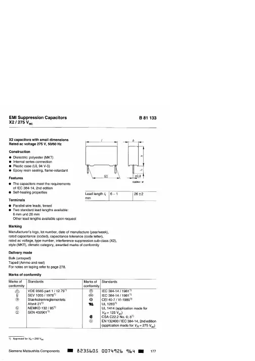
B81133-C1333中文资料
- 格式:pdf
- 大小:126.91 KB
- 文档页数:3


Designation:D1238–04Standard Test Method forMelt Flow Rates of Thermoplastics by Extrusion Plastometer1This standard is issued under thefixed designation D1238;the number immediately following the designation indicates the year of original adoption or,in the case of revision,the year of last revision.A number in parentheses indicates the year of last reapproval.A superscript epsilon(e)indicates an editorial change since the last revision or reapproval.1.Scope*1.1This test method covers measurement of the rate of extrusion of molten resins through a die of a specified length and diameter under prescribed conditions of temperature,load, and piston position in the barrel as the timed measurement is being made.1.2Procedure A is a manual cutoff operation based on time used for materials havingflow rates that fall generally between 0.15and50g/10min.Procedure B is an automatically timed flow rate measurement used for materials havingflows from 0.50to900g/10min.By both procedures,the piston travel is generally the same during the timed measurement;the piston foot is about46and20.6mm above the parableflow rates have been obtained by these procedures in interlaboratory round-robin measurements of several materials described in 13.1.Provision is made for calculation of melt volume-flow rate as well as melt mass-flow rate.N OTE1—Round-robin testing indicates this test method may be suit-able atflow rates up to1500g/10min if the timing clock resolves the elapsed time to the nearest0.01s.N OTE2—This test method and ISO1133-1991are technically equiva-lent.1.3This standard does not purport to address the safety concerns,if any,associated with its use.It is the responsibility of the user of this standard to establish appropriate safety and health practices and determine the applicability of regulatory limitations prior to use.Specific precautionary statements are given in5.7,10.2.12,and14.1.2.2.Referenced Documents2.1ASTM Standards:2D618Practice for Conditioning Plastics for TestingD883Terminology Relating to PlasticsE691Practice for Conducting an Interlaboratory Study toDetermine the Precision of a Test Method2.2ANSI Standard:B46.1on Surface Texture32.3ISO Standard:ISO1133-1991Determination of the Melt-Mass Flow Rate (MFR)and the Melt V olume-Flow Rate(MVR)of Ther-moplastics33.Terminology3.1General:3.1.1For definition of some of the technical terms used in this test method refer to Terminology D883.4.Significance and Use4.1This test method is particularly useful for quality control tests on thermoplastics.N OTE3—Polymers havingflow rates less than0.15or greater than900 g/10min may be tested by the procedures in this test method;however, precision data have not been developed.4.2This test method serves to indicate the uniformity of the flow rate of the polymer as made by an individual process and, in this case,may be indicative of uniformity of other proper-ties.However,uniformity offlow rate among various polymers as made by various processes does not,in the absence of other tests,indicate uniformity of other properties.4.3Theflow rate obtained with the extrusion plastometer is not a fundamental polymer property.It is an empirically defined parameter critically influenced by the physical proper-ties and molecular structure of the polymer and the conditions of measurement.The rheological characteristics of polymer melts depend on a number of variables.Since the values of these variables occurring in this test may differ substantially from those in large-scale processes,test results may not correlate directly with processing behavior.4.4Theflow rate of a material may be measured under any of the conditions listed for it in8.2.Additional characterization of a material can be obtained if more than one condition is used.In case two conditions are employed,a Flow Rate Ratio (FRR)may be obtained by dividing theflow rate at one condition by theflow rate at the other condition.1This test method is under the jurisdiction of ASTM Committee D20on Plastics and is the direct responsibility of Subcommittee D20.30on Thermal Properties (Section D20.30.08).Current edition approved March1,2004.Published April2004.Originally approved st previous edition approved in2001as D1238-01e1.2For referenced ASTM standards,visit the ASTM website,,or contact ASTM Customer Service at service@.For Annual Book of ASTMStandards volume information,refer to the standard’s Document Summary page on the ASTM website.3Available from American National Standards Institute(ANSI),25W.43rd St., 4th Floor,New York,NY10036.1*A Summary of Changes section appears at the end of this standard. Copyright©ASTM International,100Barr Harbor Drive,PO Box C700,West Conshohocken,PA19428-2959,United States.5.Apparatus5.1Plastometer :5.1.1The apparatus shall be a dead-weight piston plastom-eter consisting of a thermostatically controlled heated steel cylinder with a die at the lower end and a weighted piston operating within the cylinder.The essential features of the plastometer,illustrated in Figs.1and 2,are described in 5.2-5.8.All dimensional measurements shall be made when the article being measured is at 2365°C.5.1.2Relatively minor changes in the design and arrange-ment of the component parts have been shown to cause differences in results among laboratories.It is important,therefore,for the best interlaboratory agreement that the design adhere closely to the description herein;otherwise,it should be determined that modifications do not influence the results.5.2Cylinder —The steel cylinder shall be 50.8mm in diameter,162mm in length with a smooth,straight hole 9.550460.0076mm in diameter,displaced 4.8mm from the cylinder axis.Wells for a thermal sensor (thermoregulator,thermistor,etc.)and thermometer shall be provided as shown in Fig.1.A 3.2-mm plate shall be attached to the bottom of the cylinder to retain the die.A hole in this plate,centered under the die and countersunk from below,allows free passage of the extrudate.The cylinder may be supported by at least two6.4-mm high-strength screws at the top (radially positioned at right angles to the applied load)or by at least two 10-mm diameter rods screwed into the side of the cylinder for attaching to a vertical support.The essential dimensions of a satisfactory cylinder of this type are shown in Fig.1(Note 4).The cylinder bore should be finished by techniques known to produce approximately 12rms or better in accordance with ANSI B46.1.N OTE 4—Cylinders made of SAE 52100or other equivalent steel heat-hardened to 60–65Rockwell Hardness Scale C give good service when used at temperatures below 200°C.Cylinder liners of cobalt-chromium-tungsten alloy are also satisfactory to 300°C.5.3Die —The outside of the steel die shall be such diameter that it will fall freely to the bottom of the 9.550460.0076mm diameter hole in the cylinder (Note 5).The die shall have a smooth straight bore 2.095560.0051mm in diameter and shall be 8.00060.025mm in length.The bore and its finish are critical.It shall have no visible drill or other tool marks and no detectable eccentricity.The die bore shall be finished by techniques known to produce approximately 12rms or better in accordance with ANSI B46.1.N OTE 5—Recommended die material is tungsten carbide.Also satisfac-tory are steel,synthetic sapphire,and cobalt-chromium-tungsten alloy.5.4Piston :5.4.1The piston shall be made of steel with an insulating bushing at the top as a barrier to heat transfer from the piston to the weight.The land of the piston shall be 9.474260.0076mm in diameter and6.3560.13mm in length.ThepistonFIG.1General Arrangement of ExtrusionPlastometerFIG.2Details of ExtrusionPlastometerdesign may incorporate means for land replacement,for example,having threads and flats immediately above the land.Above the land,the piston shall be no larger than 8.915mm in diameter (Note 6).The finish of the piston foot shall be 12rms in accordance with ANSI B46.1.If wear or corrosion is a problem,the piston should be of stainless steel and equipped with a detachable foot for ease of replacement.N OTE 6—To improve standardization it is preferable that the piston be guided with a loose-fitting metal sleeve at the top of the cylinder.N OTE 7—Pistons of SAE 52100steel with the bottom 25mm,including the foot,hardened to a Rockwell hardness,C scale,of 55to 59have been found to give good service when used at temperatures below 200°C.5.4.2The piston shall be scribed with two reference marks 4mm apart in such fashion that when the lower mark coincides with the top of the cylinder or other suitable reference point,the bottom of the piston is 48mm above the top of the die (see Fig.1).5.4.3The combined weight of piston and load shall be within a tolerance of 60.5%of the selected load.5.5Heater :5.5.1The equipment must have a heater capable of heating the apparatus so that the temperature at 10mm above the die can be maintained within 60.2°C of the desired temperature during the test.The temperature of the barrel,from 10mm to 75mm above the top of the die,must be maintained within 61%of the set temperature (°C).N OTE 8—At temperatures higher than 200°C this degree of temperature control may be more difficult to obtain.5.5.2Calibrate the temperature-indicating device by means of a light-gage probe-type thermocouple or a platinum-resistance temperature sensor having a short sensing length.4The thermocouple should be encased in a metallic sheath having a diameter of approximately 1.6mm with its hot junction grounded to the end of the sheath.Insert the tempera-ture sensor into the melt from the top of the cylinder so that it is 1061mm above the upper face of the die.The temperature sensors shall be used with a potentiometer having a sensitivity of at least 0.005mV ,or a temperature readout having a sensitivity of at least 0.1°C.Calibration should also be verified at 75mm above the upper face of the die.An alternate technique for calibration is to use a sheathed thermocouple or platinum-resistance temperature sensor with tip diameter of 9.460.1mm for insertion in the bore without material present.An example of this is shown in Fig.3.Calibration of the temperature-indicating device shall be verified at each run temperature.N OTE 9—The response of the temperature sensing device may be affected by immersion level.Take care to ensure adequate insulation of the device sensor and stabilization of the barrel temperature.5.5.3Heat shall be supplied by electric band heater(s)covering the entire length of the cylinder.The heater(s)may be single-or multi-element,depending upon the manufacturer’s control means.The heater(s)plus control system must be capable of maintaining the temperature within the required 60.2°C of the set point.The temperature sensor and readout equipment must be calibrated to a traceable national standard4Round-robin data showing flow rate and corresponding temperature profile of the melt obtained using probe-type thermocouples and platinum resistance tempera-ture sensors can be obtained from ASTM Headquarters.RequestRR:D20-1094.FIG.3Example of a Temperature Calibration DeviceNote A—Mineral glass insulation or equivalent spacer shall be bonded to tip and SS tube.Bond material shall be low conductivity type,400°C minimum rating.Insulation jacket material shall be low conductivity type (400°C minimum rating preferred,see Note 5).Note B—The RTD shall be inserted into bronze tip and bonded using high conductivity,400°C rated material.Tip of RTD element shall touch the bronze tip.Minimum insertion depth of 11.2mm clearance between RTD and tip wall shall beminimized.(that is,NIST)at least once per year.The cylinder with the heater(s)shall be lagged with38mm of foamed-glass insula-tion.An insulating plate3.2mm in thickness shall be attached to the bottom of the cylinder to minimize heat loss at this point.5.6Temperature Controller—The type of controller and sensor must be capable of meeting the required control tolerance specified in5.5.1.5.7Thermometer—Thermometers having a range of4°C graduated in0.2°C divisions may be used to indicate tempera-ture.The temperature at this point may not necessarily be the temperature of the material10mm above the die.The thermometer may be used to monitor indirectly the temperature of the material10mm above the die and may be calibrated by reference to a thermocouple or platinum resistance temperature sensor inserted in the material10mm above the die.See5.5.2 for a description of a method for measuring temperature. Warning—Caution should be observed with the use of a mercury-filled thermometer.Mercury vaporization occurs if the thermometer is broken.Mercury thermometers are not to be used at or above the boiling point of mercury,which is357°C. N OTE10—Warning:5.8Level—Provision shall be made for vertical alignment of the bore of the extrusion plastometer.This is necessary to minimize subtractive loads resulting from rubbing or friction between the piston tip and sidewall.Means of alignment are discussed in Appendix X1.5.9Accessory Equipment—Necessary accessories include equipment for charging samples to the cylinder,a funnel,a die plug,a tool for cutting off the extruded sample,a timer or stop watch,cleaning equipment,go/no-go gages,a balance accurate to60.001g,and,when required,a weight or weight-piston support.N OTE11—Satisfactory operation of the apparatus for polyethylenes can be ascertained by making measurements on NIST Standard Reference Materials(SRMs)certified for meltflow rate.The four SRMs certified under condition190/2.16are SRM1473with aflow rate of1.29g/min, SRM1474with aflow rate of5.03g/10min,SRM1496with aflow rate of0.26g/10min,and SRM1497with aflow rate of0.19g/10min.SRM 1475a is certified under condition190/3.25with aflow rate of2.20g/10 min.56.Test Specimen6.1The test specimen may be in any form that can be introduced into the bore of the cylinder,for example,powder, granules,strips offilm,or molded slugs.It may be desirable to preform or pelletize a powder.7.Conditioning7.1Many thermoplastic materials do not require condition-ing prior to testing.Materials which contain volatile compo-nents,are chemically reactive,or have other special character-istics most probably require appropriate conditioning procedures.Moisture not only affects reproducibility offlow rate measurement but,in some types of materials,degradation is accelerated by moisture at the high temperatures used in testing.Check the applicable material specification for any conditioning requirements before using this test.See Practice D618for appropriate conditioning practices.8.Procedural Conditions8.1Standard conditions of test are given in Table1.Test conditions shall be shown as:Condition___/___,where the temperature in degrees Celsius is shownfirst,followed by the weight in kilograms.For example:Condition190/2.16.8.2The following conditions have been found satisfactory for the material listed:Material Condition Acetals(copolymer and homopolymer)190/2.16190/1.05 Acrylics230/1.2230/3.8 Acrylonitrile-butadiene-styrene200/5.0230/3.8220/10Acrylonitrile/butadiene/styrene/polycarbonate230/3.8250/1.2blends265/3.8265/5.0 Cellulose esters190/0.325190/2.16190/21.60210/2.16 Ethylene-chlorotrifluoroethylene copolymer271.5/2.16Ethylene-tetrafluoroethylene copolymer297/5.0Nylon275/0.325235/1.0235/2.16235/5.0275/5.0Perfluoro(ethylene-propylene)copolymer372/2.16Perfluoroalkoxyalkane372/5.0Polycaprolactone125/2.1680/2.16 Polychlorotrifluorethylene265/12.5Polyether sulfone(PES)380/2.16360/10343/2.16Polyethylene125/0.325125/2.16250/1.2190/0.325190/2.16190/21.60190/10310/12.5Polycarbonate300/1.2Polymonochlorotrifluoroethylene265/21.6265/31.6Polypropylene230/2.16Polyphenyl sulfone(PPSU)365/5.0380/2.16 Polystyrene200/5.0230/1.2230/3.8190/5.0 Polysulfone(PSU)343/2.16360/10 Polyterephthalate250/2.16210/2.16285/2.16Poly(vinyl acetal)150/21.6Poly(vinylidenefluoride)230/21.6230/5.0Poly(phenylene sulfide)315/5.0Styrene acrylonitrile220/10230/10230/3.8Styrenic Thermoplastic Elastomer190/2.16200/5.0 Thermoplastic Elastomer-Ether-Ester190/2.16220/2.16230/2.16240/2.16250/2.16 Thermoplastic elastomers(TEO)230/2.16Vinylidenefluoride copolymers230/21.6230/5.0for T m=100°use120/5.0or21.6N OTE12—Some materials may require special materials of construc-tion or handling for performing this test.Please refer to the material specification for appropriate recommendations.8.3If more than one condition is used and the material is polyethylene,the determination of Flow Rate Ratio(FRR)has been found to be useful.The FRR is a dimensionless number derived by dividing theflow rate at Condition190/10by the flow rate at Condition190/2.16.N OTE13—When determining such a ratio offlow rates for a material at5These standard polyethylenes are available from the National Institute of Standards and Technology,Office of Standard Reference Materials,Washington,DC20234.the same temperature under different loads,it has been found that precision is maximized when one operator uses one Procedure (A or B),the same plastometer,and the same die for both measurements (the die need not be removed from the plastometer between the two determina-tions).9.Procedure A—Manual Operation9.1Select conditions of temperature and load from Table 1in accordance with material specifications such that flow rates will fall between 0.15to 50g/10min.9.2Ensure that the bore of the extrusion plastometer is properly aligned in the vertical direction.(See Appendix X1.)9.3Inspect the apparatus and die for cleanliness.If it is not clean,see 9.11.N OTE 14—The degree of cleanliness can significantly influence the flow rate results,therefore a thorough method of cleaning must be established.It has been found that three swabs of the barrel is satisfactory for most materials and that the die,barrel,and piston are more easily cleaned while hot.9.4Check the die bore diameter with appropriately sized no-go/go gages prior to testing.Make frequent checks to determine whether the die diameter (tested with die at 2365°C)is within the tolerances given in 5.3.N OTE 15—Cleaning and usage can result in a die diameter that is out of specifications.Data has shown that erroneous results will be obtained if the die diameter is not within the appropriate tolerances.9.5Verify that the temperature is stable and within 60.2°C of the appropriate test temperature as specified in 5.5.1.9.6Insert the die and the piston.The temperature of the cylinder with the piston and die in place must be stable at the appropriate test temperature 15min before testing is begun.When equipment is used repetitiously,it should not be neces-sary to heat the piston and die for 15min.N OTE 16—The reduction in heating time when the unit is being used repetitiously is only allowed when runs of the same or similar material are being measured over a continuous time frame.If the piston and die are removed and cleaned,they should be considered “cold”and the full 15minutes heating stabilization time required.9.7Remove the piston and place it on an insulated surface.Charge the cylinder within 1min with a weighed portion of the sample in accordance with the expected flow rate,as given in Table 2.Reinsert the piston and add the appropriate weight.N OTE 17—Experience has shown that for the best reproducibility the piston should operate within the same part of the cylinder for each measurement.The piston is scribed so the starting point for each extrusion is roughly the same.Some excess of material over the minimum required for the actual flow measurement portion of the test is provided by the charging weights shown in Table 2.This is necessary to achieve a void-free extrudate and flow equilibrium before start of rate measure-ments.N OTE 18—It is frequently helpful to take interim cuts of the extrudate at uniform time intervals during the specified extrusion time.Weights ofTABLE 1Standard Test Conditions,Temperature,and LoadCondition Temperature,°CTotal Load Including Piston,kgApproximate PressureStandard DesignationkPa psi 80/2.1680 2.16125/0.3251250.32544.8 6.5125/2.16125 2.16298.243.25150/2.16150 2.16298.243.25190/0.3251900.32544.8 6.5190/2.16190 2.16298.243.25190/21.6019021.602982.2432.5200/5.0200 5.0689.5100.0230/1.2230 1.2165.424.0230/3.8230 3.8524.076.0265/12.526512.51723.7250.0275/0.3252750.32544.8 6.5230/2.16230 2.16298.243.25190/1.05190 1.05144.721.0190/10.019010.01379.0200.0300/1.2300 1.2165.424.0190/5.0190 5.0689.5100.0235/1.0235 1.0138.220.05235/2.16235 2.16298.243.25235/5.0235 5.0689.5100.0250/2.16250 2.16298.243.25310/12.531012.51723.7250.0210/2.16210 2.16298.243.25285/2.16285 2.16298.243.25315/5.0315 5.0689.5100.0372/2.16372 2.16298.243.25372/5.0372 5.0689.5100297/5.0297 5.0689.5100230/21.623021.62982.2432.5230/5.0230 5.0689.5100265/21.626521.62982.2432.5265/31.626531.64361.2632.5271.5/2.16271.5 2.16298.243.25220/1022010.01379.0200.0250/1.2250 1.2165.424.0265/3.8265 3.8524.076.0265/52655.0689.5100.0these individual cuts give an indication of the presence of bubbles which may be masked due to their size or to opacity of the sample.This technique is particularly helpful in the case of highly pigmented materials.Forcing out some of the resin manually during the preheat period often eliminates bubbles in the test extrudate.9.8Allow time for the material to soften and begin to melt,and then purge some material to a position such that subse-quent travel of the piston will position the lower scribe mark at the reference start position 7.060.5min from the completion of the charge.Purge must be completed at least 2min prior to start of the test for materials having melt flow rates less than 10g/10min.N OTE 19—It has been found that purging within 60s of the start time will result in higher variability in the data.N OTE 20—There may be cases where the 7.060.5min is too much or not enough preheat time.For those materials,provisions must be in the material documents.It is necessary to refer to the appropriate material document before beginning any test.N OTE 21—Additional care may be necessary to prevent thermal degra-dation in the extrusion plastometer.This is sometimes done by the addition of an appropriate antioxidant.For highly unstable materials,it may be necessary to use alternative techniques as an indication of flow charac-teristics.9.9For materials with flow rates greater than 10g/10min,a weight (and if needed,a piston)support must be used after the initial purge.The support shall be removed at such a time as to allow the test to begin within 760.5min of the completion of the charge.The piston/weight support should be of such a length that the lower scribe mark of the supported piston/weight will be 25mm above the top of the guide bushing or other suitable reference mark.N OTE 22—It has been found that the effect of choosing plugging,weight support,or both,is significant to the flow rate results.The choice of piston support was made to cover all conditions and flow rates 10to 50g/10min.9.10For all tests,start collecting a timed extrudate when requirements for the piston position are met,provided this iswithin 7.060.5min from the end of charging;otherwise,discard the charge and repeat the test with readjusted piston position after the initial purge,or change weights.Require-ments are that the top scribed mark on the piston be visible above the cylinder or index and that the lower scribe mark be in the cylinder or below the index.As the lower scribed mark approaches the top of the cylinder or index,reset the timer to zero,then simultaneously start the timer and make the initial cut-off when the position requirements are met.Make the final cut-off exactly when the time interval given in Table 2is reached.Collect the timed extrudate.If the extrudate contains visible bubbles,discard the complete charge and begin the test again.N OTE 23—The charge weight should only be increased if no material is being purged and there is still not enough material to complete the test.9.11Discharge the remainder of the specimen and push the die out through the top of the cylinder.Swab out the cylinder with cloth patches after the manner of cleaning a pistol barrel.The die may be cleaned by dissolving the residue in a solvent.A better method is pyrolytic decomposition of the residue in a nitrogen atmosphere.Place the die in a tubular combustion furnace or other device for heating to 550610°C and clean with a small nitrogen purge through the die.This method is preferable to flame or solvent cleaning,being faster than solvent cleaning and less detrimental to the die than an open flame.In certain cases where materials of a given class having similar flow characteristics are being tested consecutively,interim die cleaning may be unnecessary.In such cases,however,the effect of cleaning upon flow rate determination must be shown to be negligible if this step is avoided.9.12Once the extrudate is cool,weigh to the nearest 1mg.9.13Multiply the weight of the extrudate by the appropriate factor shown in Table 2to obtain the flow rate in grams per 10min.N OTE 24—Frequently,errors in test technique,apparatus geometry,or test conditions,which defy all but the most careful scrutiny exist,causing discrepancy in flow rate determinations.The existence of such errors is readily determined by periodically measuring a reference sample of known flow rate.The flow rate value and range to be tolerated can be determined using a statistically correct test program composed of multiple determinations with various instruments.Standard samples of polyethyl-ene,linear or branched,are available from the National Institute of Standards and Technology.9.14In case a specimen has a flow rate at the borderline of the ranges in Table 2and slightly different values are obtained at different time intervals,the referee value shall be obtained at the longer time interval.10.Procedure B—Automatically Timed Flow RateMeasurement 10.1Apparatus :10.1.1Extrusion plastometer and auxiliary equipment are detailed in Section 4and below.10.1.2A timing device shall electrically,optically,or me-chanically time piston movement within the specified travel range.The requirements of the system are as follows:10.1.2.1Sense and indicate the piston travel time within 60.01s (see Note 1).TABLE 2Standard Test Conditions,Sample Mass,A and TestingTime BFlow Range,g/10min Suggested Mass of Sample in Cylinder,gTime Inter-val,min Factor for Obtaining Flow Rate in g/10min0.15to 1.0 2.5to 3.0 6.00 1.67>1.0to 3.5 3.0to 5.0 3.00 3.33>3.5to 10 4.0to 8.0 1.0010.00>10to 25 4.0to 8.00.5020.00>254.0to 8.00.2540.00AThis is a suggested mass for materials with melt densities of about 0.7g/cm 3.Correspondingly,greater quantities are suggested for materials of greater melt densities.Density of the molten resin (without filler)may be obtained using the procedure described by Terry,B.W.,and Yang,K.,“A New Method for Determining Melt Density as a Function of Pressure and Temperature,”SPE Journal ,SPEJA,Vol.20,No.6,June 1964,p.540or the procedure described by Zoller,Paul,“The Pressure-Volume-Temperature Properties of Polyolefins,”Journal of Applied Poly-mer Science ,Vol 23,1979,p.1051.It may also be obtained from the weight of an extruded known volume of resin at the desired temperature.For example,25.4mm (1in.)of piston movement extrudes 1.804cm 3of resin.An estimate of the density of the material can be calculated from the following equation:resin density at test temperature 5M /1.804where:M =mass of extruded resin.BSee9.14.。
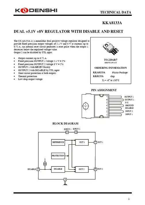
TECHNICAL DATAKK A8133ADUAL +5.1V +8V REGULATOR WITH DISABLE AND RESETTO-220AB/7HEPTAWAT ORDERING INFORMATIONKK A8133A Plastic PackageKK 8133A chipT J= -0° to 130°CThe KK A8133A is a monolithic dual positive voltage regulator designed toprovide fixed precision output voltages of 5.1 V and 8 V at currents up to0.75 A. An internal reset circuit generates a reset pulse when the output 1decreases below the regulated voltage value.Output 2 can be disabled by TTL input.Output currents up to 0.75 A• • • • • • • • Fixed precision OUTPUT 1 voltage 5.1 V ± 2% Fixed precision OUTPUT 2 voltage 8 V ± 2% OUTPUT 1 with RESET facility OUTPUT 2 with DISABLE by TTL inputShort circuit protection at both outputsThermal protection Low drop output voltage PIN ASSIGNMENT1INPUT 1INPUT 2DISABLE GROUND N.C.OUTPUT 1OUTPUT 2234567BLOCK DIAGRAMDISABLE REFERENCE OUT 1OUT 1INPUT 1INPUT 2OUT 2OUT 2DISABLE 34176PROTECTION2MAXIMUM RATINGS *Symbol Parameter Min Max UnitV IN1DC Input Voltage Pin 1 20 V V IN2DC Input Voltage Pin 2 20 V V DIS Disable Input Voltage Pin 3 20 V I O1,2 SC Short Circuit Output Current V IN1 = 7 V, V IN2 = 10 V 1.6 AV IN1 = V IN2 = 16 V1.0 Tstg Storage Temperature-65 150 °C T JJunction Temperature150°C*Maximum Ratings are those values beyond which damage to the device may occur. Functional operation should be restricted to the Recommended Operating Conditions.RECOMMENDED OPERATING CONDITIONSSymbol Parameter Min Max UnitV IN1DC Input Voltage Pin 1 7.0 14 V V IN2DC Input Voltage Pin 2 10 14 V V DIS Disable Input Voltage Pin 3 0 7.0 V I O1,2Output Currents 1.0 A T JJunction Temperature130°CTHERMAL DATASymbol Parameter Vlalue UnitRth (j-c) Maximum Thermal Resistance Junction-case 6 o C/W Rth (j-a)Maximum Thermal Resistance Junction-ambient60oC/WELECTRICAL CHRACTERISTICS(V IN1 = 7 V, V IN2 = 10 V, T J = 25°C, unless otherwise specified)Guaranteed Limit Symbol Parameter TestConditionsMin MaxUnitV O1Output Voltage V IN1 = 7 V, V IN2 = 10 V,V DIS = 2.0 V, I O1= -10 mA5.0 5.2 V7 V ≤ V IN2 ≤ 14 V,-5 mA ≤ I O1 ≤ -750 mA, V DIS = 2.0 V4.95.3V O2Output Voltage V IN1 = 7 V, V IN2 = 10 V,I O2= -10 mA7.84 8.16 V10 V ≤ V IN2 ≤ 14 V,-5 mA ≤ I O1 ≤ -750 mA,V DIS = 2.0 V, V IN1 = 7 V7.7 8.3∆ V O1 LI Line Regulation 7 V ≤ V IN2 ≤ 14 V, I O1 = -200 mA, V DIS= 2.0 V, V IN2 = 10 V 50mV∆ V O2 LI10 V ≤ V IN2 ≤ 14 V, I O2 = -200 mA,V DIS = 2.0 V, V IN1 = 7 V80∆ V O1 LO Load Regulation V IN1 = 7 V, V IN2 = 10 V, -5 mA ≤ I O1 ≤ -0.6 mA, V DIS = 2.0 V 100mV∆ V O2 LO V IN1 = 7 V, V IN2 = 10 V,-5 mA ≤ I O2 ≤ -0.6 mA, V DIS = 2.0 V160 V IO1,2Dropout Voltage I O1,2 = -750 mA, V DIS = 2.0 V 1.4 VI O1,2 = -1.0 mA, V DIS = 2.0 V 2.0I Q Quiescent Current V IN1 = 7 V, V IN2 = 10 V,V DIS = 0.8 V, I O1= -10 mA 2.0mAI DIS Disable Bias Current 0 V ≤ V DIS ≤ 7 V,V IN1 = 7 V, V IN2 = 10 V-100 2.0 µAV DISH Disable Voltage High(out 2 active)V IN1 = 7 V, V IN2 = 14 V 2 VV DISL Disable Voltage Low(out 2 disabled)V IN1 = 7 V, V IN2 = 14 V 0.8 VTYPICAL APPLICATIONINPUT 1 (01)OUTPUT 1 (07)OUTPUT 2 (06)NC (05)DISABLE (03) GROUND (04)C3C4C2KK A8133AC1INPUT 2 (02)C1 to C4 = 10 MfTO-220 AB/7。