重庆一中陈国君共26页文档
- 格式:ppt
- 大小:2.44 MB
- 文档页数:26
本文部分内容来自网络整理,本司不为其真实性负责,如有异议或侵权请及时联系,本司将立即删除!== 本文为word格式,下载后可方便编辑和修改! ==第一中文网篇一:第一中文网网站简介网站简介第一中文网是免费小说阅读网站。
成立于201X年,经过短短1年时间努力。
本网大力发展推理小说的创作。
提供最新最好看的小说,包含玄幻魔法,武侠仙侠,都市言情,网游动漫,科幻灵异,历史军事等上万本小说免费在线阅读和小说txt下载,没有影响阅读的弹框广告,力争做最优秀的绿色和谐小说网站。
第一中文网定位于广大书友爱好者,所有用户及内容都来自于对小说的执着、热爱。
热爱和关注小说的人们。
本站力于打造纯正的免费网络小说社区,为广大小说爱好者提供良好的阅读平台、分享平台。
网站特色第一中文网提供:玄幻魔法,武侠仙侠,都市言情,历史军事,侦探推理,网游动漫,科幻小说,恐怖灵异,其他小说等全本小说、连载小说阅读和txt小说下载。
我们以最优质的服务,给你舒适的阅读享受!网站宗旨以广大书友的方便为目标,以广大书友的方便为核心,以绿色无烦人广告为导向,只要你想看的,告诉我们!我们会以最快的速度给予更新!宣传内容都市小说、言情小说、修真小说、玄幻小说、灵异小说、武侠小说、恐怖小说、历史小说、军事小说、科幻小说、侦探小说、推理小说等全本小说、连载小说的免费小说阅读和小说txt等各方面小说综合发展。
做最好的免费小说阅读网站!网站帮助如何成为会员第一步,点击网站首页的注册链接。
第二步,填写相关资料。
第三步,完成注册,成为会员。
如何成为作者一,首先您必须是第一中文网的注册用户,在注册会员资料填写完成后可以直接申请成为作者。
二,当您拥有自己的注册账号时想自己创作作品的话可点击用户中心左上方的作者申请,阅读相关协议并同意后可以申请成为作者。
三,点击完成后将自己的作品抽出一小部份填进内容里面方便后台编辑的审核,一旦通过审核您就能成为本站作者。
投稿内容一,作品必须不能含有色情,暴力,政治因素的题材。
新教材第2课时集合的表示学习目标 1.初步掌握集合的两种表示方法——列举法、描述法,感受集合语言的意义和作用.2.会用集合的两种表示方法表示一些简单集合.知识点一列举法把集合的所有元素一一列举出来,并用花括号“{}”括起来表示集合的方法叫做列举法.知识点二描述法一般地,设A是一个集合,把集合A中所有具有共同特征P(x)的元素x所组成的集合表示为{x∈A|P(x)},这种表示集合的方法称为描述法.思考不等式x-2<3的解集中的元素有什么共同特征?答案元素的共同特征为x∈R,且x<5.1.由1,1,2,3组成的集合可用列举法表示为{1,1,2,3}.(×)2.集合{(1,2)}中的元素是1和2.(×)3.集合A={x|x-1=0}与集合B={1}表示同一个集合.(√)4.{x|x>1}与{y|y>1}是不同的集合.(×)一、列举法表示集合例1用列举法表示下列集合:(1)不大于10的非负偶数组成的集合;(2)方程x2=2x的所有实数解组成的集合;(3)直线y=2x+1与y轴的交点所组成的集合;(4)由所有正整数构成的集合.解(1)因为不大于10是指小于或等于10,非负是大于或等于0的意思,所以不大于10的非负偶数集是{0,2,4,6,8,10}.(2)方程x2=2x的解是x=0或x=2,所以方程的解组成的集合为{0,2}.(3)将x=0代入y=2x+1,得y=1,即交点是(0,1),故交点组成的集合是{(0,1)}.(4)正整数有1,2,3,…,所求集合为{1,2,3,…}.反思感悟 用列举法表示集合应注意的两点(1)应先弄清集合中的元素是什么,是数还是点,还是其他元素;(2)若集合中的元素是点时,则应将有序实数对用小括号括起来表示一个元素.跟踪训练1 用列举法表示下列给定的集合:(1)大于1且小于6的整数组成的集合A ;(2)方程x 2-9=0的实数根组成的集合B ;(3)一次函数y =x +2与y =-2x +5的图象的交点组成的集合D .解 (1)因为大于1且小于6的整数包括2,3,4,5,所以A ={2,3,4,5}.(2)方程x 2-9=0的实数根为-3,3,所以B ={-3,3}.(3)由⎩⎪⎨⎪⎧ y =x +2,y =-2x +5,得⎩⎪⎨⎪⎧x =1,y =3,所以一次函数y =x +2与y =-2x +5的交点为(1,3),所以D ={(1,3)}.二、描述法表示集合例2 用描述法表示下列集合:(1)正偶数集;(2)被3除余2的正整数集合;(3)平面直角坐标系中坐标轴上的点组成的集合.解 (1)偶数可用式子x =2n ,n ∈Z 表示,但此题要求为正偶数,故限定n ∈N *,所以正偶数集可表示为{x |x =2n ,n ∈N *}.(2)设被3除余2的数为x ,则x =3n +2,n ∈Z ,但元素为正整数,故n ∈N ,所以被3除余2的正整数集合可表示为{x |x =3n +2,n ∈N }.(3)坐标轴上的点(x ,y )的特点是横、纵坐标中至少有一个为0,即xy =0,故平面直角坐标系中坐标轴上的点的集合可表示为{(x ,y )|xy =0}.反思感悟 利用描述法表示集合应关注五点(1)写清楚该集合代表元素的符号.例如,集合{x ∈R |x <1}不能写成{x <1}.(2)所有描述的内容都要写在花括号内.例如,{x ∈Z |x =2k },k ∈Z ,这种表达方式就不符合要求,需将k ∈Z 也写进花括号内,即{x ∈Z |x =2k ,k ∈Z }.(3)不能出现未被说明的字母.(4)在通常情况下,集合中竖线左侧元素的所属范围为实数集时可以省略不写.例如,方程x2-2x+1=0的实数解集可表示为{x∈R|x2-2x+1=0},也可写成{x|x2-2x+1=0}.跟踪训练2下列三个集合:①A={x|y=x2+1};②B={y|y=x2+1};③C={(x,y)|y=x2+1}.(1)它们是不是相同的集合?(2)它们各自的含义分别是什么?解(1)不相同.(2)集合A={x|y=x2+1}的代表元素是x,且x∈R,所以{x|y=x2+1}=R,即A=R;集合B ={y|y=x2+1}的代表元素是y,满足条件y=x2+1的y的取值范围是y≥1,所以{y|y=x2+1}={y|y≥1}.集合C={(x,y)|y=x2+1}的代表元素是(x,y),是满足y=x2+1的数对.可以认为集合C是由坐标平面内满足y=x2+1的点(x,y)构成的.三、集合表示法的综合应用例3集合A={x|kx2-8x+16=0},若集合A中只有一个元素,求实数k的值组成的集合.解(1)当k=0时,方程kx2-8x+16=0变为-8x+16=0,解得x=2,满足题意;(2)当k≠0时,要使集合A={x|kx2-8x+16=0}中只有一个元素,则方程kx2-8x+16=0有两个相等的实数根,所以Δ=64-64k=0,解得k=1,此时集合A={4},满足题意.综上所述,k=0或k=1,故实数k的值组成的集合为{0,1}.延伸探究1.本例若将条件“只有一个元素”改为“有两个元素”,其他条件不变,求实数k的值组成的集合.解由题意可知,方程kx2-8x+16=0有两个不等实根,故k≠0,且Δ=64-64k>0,即k<1,且k≠0.所以实数k组成的集合为{k|k<1,且k≠0}.2.本例若将条件“只有一个元素”改为“至少有一个元素”,其他条件不变,求实数k的取值范围.解由题意可知,方程kx2-8x+16=0至少有一个实数根.①当k=0时,由-8x+16=0得x=2,符合题意;②当k≠0时,要使方程kx2-8x+16=0至少有一个实数根,则Δ=64-64k≥0,即k≤1,且k≠0.综合①②可知,实数k的取值范围为{k|k≤1}.反思感悟(1)若已知集合是用描述法给出的,读懂集合的代表元素及其属性是解题的关键,如例3集合A中的元素就是所给方程的根,由此便把集合的元素个数问题转化为方程的根的个数问题.(2)在学习过程中要注意数学素养的培养,如本例中用到了等价转化思想和分类讨论的思想.1.用列举法表示集合{x|x2-2x-3=0}为()A.{-1,3} B.{(-1,3)}C.{x=1} D.{x2-2x-3=0}答案 A2.一次函数y=x-3与y=-2x的图象的交点组成的集合是()A.{1,-2} B.{x=1,y=-2}C.{(-2,1)} D.{(1,-2)}答案 D3.设A={x∈N|1≤x<6},则下列正确的是()A.6∈A B.0∈A C.3∉A D.3.5∉A答案 D4.第一象限的点组成的集合可以表示为()A.{(x,y)|xy>0} B.{(x,y)|xy≥0}C.{(x,y)|x>0且y>0} D.{(x,y)|x>0或y>0}答案 C5.下列集合不等于由所有奇数构成的集合的是()A.{x|x=4k-1,k∈Z}B.{x|x=2k-1,k∈Z}C.{x|x=2k+1,k∈Z}D.{x|x=2k+3,k∈Z}答案 A1.知识清单:(1)描述法表示集合的理解.(2)用列举法和描述法表示集合.(3)两种表示法的综合应用.2.方法归纳:等价转化、分类讨论.3.常见误区:点集与数集的区别.1.用列举法表示集合{x|x2-2x+1=0}为()A.{1,1} B.{1}C.{x=1} D.{x2-2x+1=0}答案 B解析方程x2-2x+1=0有两个相等的实数解1,根据集合元素的互异性知B正确.2.已知集合A={x|x(x-1)=0},那么下列结论正确的是()A.0∈A B.1∉A C.-1∈A D.0∉A答案 A解析∵A={x|x(x-1)=0}={0,1},∴0∈A.3.如果A={x|x>-1},那么()A.-2∈A B.{0}∈A C.-3∈A D.0∈A答案 D解析∵0>-1,故0∈A,选D.4.下列集合中,不同于另外三个集合的是()A.{x|x=1} B.{x|x2=1}C.{1} D.{y|(y-1)2=0}答案 B解析{x|x2=1}={-1,1},另外三个集合都是{1},故选B.5.下列命题中正确的是()A.集合{x∈R|x2=1}中有两个元素B.集合{0}中没有元素C.13∈{x|x<23}D.{1,2}与{2,1}是不同的集合答案 A解析{x∈R|x2=1}={1,-1};集合{0}是单元素集,有一个元素,这个元素是0;{x|x<23}={x|x<12},13>12,13∉{x|x<23};根据集合中元素的无序性可知{1,2}与{2,1}是同一个集合.6.能被2整除的正整数的集合,用描述法可表示为________________________.答案{x|x=2n,n∈N*}解析正整数中所有的偶数均能被2整除.7.已知集合A={x|2x+a>0},且1∉A,则实数a的取值范围是________________.答案{a|a≤-2}解析∵1∉{x|2x+a>0},∴2×1+a≤0,即a≤-2.8.已知-5∈{x|x2-ax-5=0},则集合{x|x2-4x-a=0}中所有元素之和为________.答案 2解析由-5∈{x|x2-ax-5=0},得(-5)2-a×(-5)-5=0,所以a=-4,所以{x|x2-4x+4=0}={2},所以集合中所有元素之和为2.9.用适当的方法表示下列集合:(1)一年中有31天的月份的全体;(2)大于-3.5小于12.8的整数的全体;(3)梯形的全体构成的集合;(4)所有能被3整除的数的集合;(5)方程(x-1)(x-2)=0的解集;(6)不等式2x-1>5的解集.解(1){1月,3月,5月,7月,8月,10月,12月}.(2){-3,-2,-1,0,1,2,3,4,5,6,7,8,9,10,11,12}.(3){a|a是梯形}或{梯形}.(4){x|x=3n,n∈Z}.(5){1,2}.(6){x|x>3}.10.已知集合A={a+3,(a+1)2,a2+2a+2},若1∈A,求实数a的值.解①若a+3=1,则a=-2,此时A={1,1,2},不符合集合中元素的互异性,舍去.②若(a+1)2=1,则a=0或a=-2.当a=0时,A={3,1,2},满足题意;当a=-2时,由①知不符合条件,故舍去.③若a2+2a+2=1,则a=-1,此时A={2,0,1},满足题意.综上所述,实数a的值为-1或0.11.设集合A={1,2,3},B={4,5},M={x|x=a+b,a∈A,b∈B},则M中元素的个数为() A.3 B.4 C.5 D.6答案 B解析1,2,3与4,5分别相加可得5,6,6,7,7,8,根据集合中元素的互异性可得集合M中有4个元素.12.已知A={1,2,3},B={2,4},定义集合A,B间的运算A*B={x|x∈A且x∉B},则集合A*B 等于()A.{1,2,3} B.{2,4} C.{1,3} D.{2}答案 C解析因为属于集合A的元素是1,2,3,但2属于集合B,所以A*B={1,3}.13.已知集合A={-1,0,1},集合B={y|y=|x|,x∈A},则B=________.答案{0,1}解析∵x∈A,∴当x=-1时,y=|x|=1;当x=0时,y=|x|=0;当x=1时,y=|x|=1.∴B ={0,1}.14.若一数集的任一元素的倒数仍在该集合中,则称该数集为可倒数集,则集合A ={-1,1,2}________(填“是”或“不是”)可倒数集.试写出一个含三个元素的可倒数集________.(答案不唯一)答案 不是 ⎩⎨⎧⎭⎬⎫1,2,12 解析 由于2的倒数12不在集合A 中,故集合A 不是可倒数集.若一个元素a ∈A ,则1a∈A .若集合中有三个元素,故必有一个元素a =1a ,即a =±1,故可取的集合有⎩⎨⎧⎭⎬⎫1,2,12,⎩⎨⎧⎭⎬⎫-1,3,13等.15.设集合A ={0,1,2},则集合B ={x -y |x ∈A ,y ∈A }中元素的个数是( )A .1B .3C .5D .9答案 C解析 因为A ={0,1,2},又集合B 中元素为x -y 且x ∈A ,y ∈A ,所以x 的可能取值为0,1,2;y 的可能取值为0,1,2.当x =0时,y =0或1或2,此时对应的x -y 的值为0,-1,-2.当x =1时,y =0或1或2,此时对应的x -y 的值为1,0,-1.当x =2时,y =0或1或2,此时对应的x -y 的值为2,1,0.综上可知,集合B ={-2,-1,0,1,2},所以集合B 中的元素的个数为5.16.设集合B =⎩⎪⎨⎪⎧⎭⎪⎬⎪⎫x ∈N ⎪⎪ 62+x ∈N . (1)试判断元素1和2与集合B 的关系;(2)用列举法表示集合B .解 (1)当x =1时,62+1=2∈N ;当x =2时,62+2=32∉N , 所以1∈B,2∉B .(2)因为62+x∈N ,x ∈N , 所以2+x 只能取2,3,6, 所以x 只能取0,1,4, 所以B ={0,1,4}.。
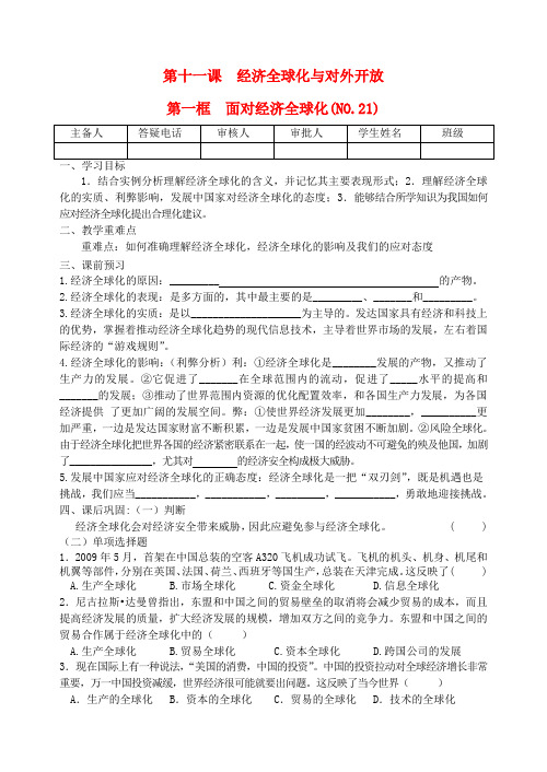
第十一课经济全球化与对外开放第一框面对经济全球化(NO.21)1.结合实例分析理解经济全球化的含义,并记忆其主要表现形式;2.理解经济全球化的实质、利弊影响,发展中国家对经济全球化的态度;3.能够结合所学知识为我国如何应对经济全球化提出合理化建议。
二、教学重难点重难点:如何准确理解经济全球化,经济全球化的影响及我们的应对态度三、课前预习1.经济全球化的原因:_________ 的产物。
2.经济全球化的表现:是多方面的,其中最主要的是_________、_______和_________。
3.经济全球化的实质:是以____________________为主导的。
发达国家具有经济和科技上的优势,掌握着推动经济全球化趋势的现代信息技术,主导着世界市场的发展,左右着国际经济的“游戏规则”。
4.经济全球化的影响:(利弊分析)利:①经济全球化是________发展的产物,又推动了生产力的发展。
②它促进了_______在全球范围内的流动,促进了_____水平的提高和_______的发展;③推动了世界范围内资源的优化配置效率,和各国生产力发展,为各国经济提供了更加广阔的发展空间。
弊:①使世界经济发展更加________,__________更加严重,一边是发达国家财富不断积累,一边是发展中国家贫困不断加剧。
②风险全球化。
由于经济全球化把世界各国的经济紧密联系在一起,使一国的经波动不可避免的殃及他国,加剧了________________,尤其对的经济安全构成极大威胁。
5.发展中国家应对经济全球化的正确态度:经济全球化是一把“双刃剑”,既是机遇也是挑战,我们应当___________,___________,_________,___________,勇敢地迎接挑战。
四、课后巩固:(一)判断经济全球化会对经济安全带来威胁,因此应避免参与经济全球化。
( ) (二)单项选择题1.2009年5月,首架在中国总装的空客A320飞机成功试飞。
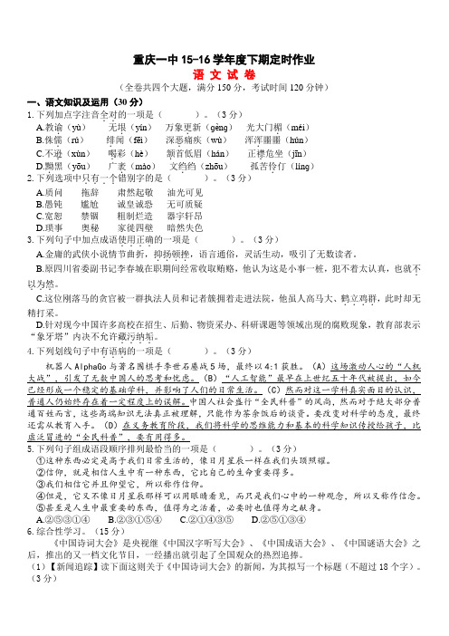
重庆一中15-16学年度下期定时作业 语 文 试 卷 (全卷共四个大题,满分150分,考试时间120分钟) 一、语文知识及运用(30分) 1.下列加点字注音全对..的一项是( )。(3分) A.教谕.(yù) 无垠.(yín) 万象更.新(ɡènɡ) 光大门楣.(méi) B.侏儒.(rú) 绯.闻(fēi) 深恶.痛疾(wù) 浑浑.噩噩(hún) C.不逊.(xùn) 喝.彩(hè) 颔.首低眉(hán) 正襟.危坐(jīn) D.黝.黑(yōu) 广袤.(mào) 文绉.绉(zhōu) 孤苦伶.仃(línɡ) 2.下列选项中只有一个....错别字的是( )。(3分)
A.质问 拖辞 肃然起敬 油光可见 B.愚钝 尴尬 诚皇诚恐 无可质疑 C.宽恕 禁锢 粗制烂造 器宇轩昂 D.琐事 奥秘 家徙四壁 暗然失色 3.下列句子中加点成语使用正确....的一项是( )。(3分)
A.金庸的武侠小说情节曲折,抑扬顿挫....,语言通俗,灵活生动,吸引了无数读者。 B.原四川省委副书记李春城在职期间经常收取贿赂,他认为这是小事一桩,犯不着太认真,也就不.
以为然...。
C.这位刚落马的贪官被一群执法人员和记者簇拥着走进法院,他虽人高马大、鹤立鸡群....,此时却无精打采。 D.针对现今中国许多高校在招生、后勤、物资采办、科研课题等领域出现的腐败现象,教育部表示“象牙塔”内决不允许藏污纳垢....。
4.下列划线句子中有语病...的一项是( )。(3分) 机器人AlphaGo与著名围棋手李世石鏖战5场,最终以4:1获胜。(A)这场激动人心的“人机大战”,引发了无数中国人的思考和忧虑。(B)“人工智能”最早在上世纪五十年代被提出,如今已经形成一个稳定的基础学科,并影响了人们的日常生活。(C)然而对这一学科真实面目的认识,普通人仍始终存在着一定程度上的误解。中国人社会盛行“全民科普”的风尚,然而对于绝大部分普通百姓而言,这些高端知识无法真正被理解,只能作为茶余饭后的谈资。要改变对科学的态度,最终还需从教育入手。(D)在义务教育阶段,我们将科学的思维能力和基本的科学知识传授给孩子,比虚泛冒进的“全民科普”,要有用得多。 5.下列句子组成语段顺序排列最恰当的一项是( )。(3分) ①这种东西必定是高于我们日常生活的,像日月星辰一样在我们头顶照耀。 ②信仰,就是相信人生中有一种东西,它比自己的生命重要得多。 ③我们相信它并且仰望它,所以称作信仰。 ④但是,它又不像日月星辰那样可以用眼睛看见,而只是我们心中的一种观念,所以又称作信念。 ⑤甚至是人生中最重要的东西,值得为之活着,必要时也值得为之献身。 A.②⑤③①④ B.②③①⑤④ C.②①④③⑤ D.②⑤①③④ 6.综合性学习。(15分) 《中国诗词大会》是央视继《中国汉字听写大会》、《中国成语大会》、《中国谜语大会》之后,推出的又一档文化节目,一经播出就引起了全国观众的热烈追捧。 (1)【新闻追踪】读下面这则关于《中国诗词大会》的新闻,为其拟写一个标题(不超过18个字)。(3分) 凤凰网讯 在央视《中国诗词大会》2月12日的第一期节目中,来自四川攀枝花市米易县的“无臂考生”彭超作为首期节目四个攻擂者之一,表现出色,一举夺得了首期擂主。 在2月12日晚,央视播出的《中国诗词大会》第一期中,当穿着绿色衬衫、袖管卷起的彭超一出场,便赢得全场热烈的掌声。彭超的故事曾激励了无数处在逆境中的人们,他幼年失去双臂,连续两次参加高考,去年以603分的成绩被四川大学法学院录取。在擂主争夺赛中,彭超迎战北大理工科的博士陈更,两人进入抢答环节。起初,陈更连续4次抢答成功,而彭超则开始落后。不过,在2比4落后,大家都以为彭超获胜无望的情况下,彭超却越战越勇,开始逆袭,最终以5比4反转获胜,成为擂主。
SURFACEVEHICLESTANDARD SAE Technical Standards Board Rules provide that: “This report is published by SAE to advance the state of technical and engineering sciences. The use of this report isentirely voluntary, and its applicability and suitability for any particular use, including any patent infringement arising therefrom, is the sole responsibility of the user.”SAE reviews each technical report at least every five years at which time it may be reaffirmed, revised, or cancelled. SAE invites your written comments and suggestions. Copyright © 2004 SAE InternationalAll rights reserved. No part of this publication may be reproduced, stored in a retrieval system or transmitted, in any form or by any means, electronic, mechanical, photocopying, recording, or otherwise, without the prior written permission of SAE.TO PLACE A DOCUMENT ORDER: Tel: 877-606-7323 (inside USA and Canada)Tel: 724-776-4970 (outside USA)2.2Related PublicationsThe following publications are for information purposes only and are not a required part of this document.2.2.1ASTM P UBLICATIONSAvailable from ASTM, 100 Barr Harbor Drive, West Conshohocken, PA 19428-2959.ASTM D 412—Test Methods for Rubber Properties in TensionASTM D 4000—Classification System for Specifying Plastic MaterialsASTM D 4066—Specification for Nylon Injection and Extrusion Materials3.Installation, Assembly, and Handling Recommendation3.1End FittingsEnd fittings can be assembled to the tubing providing that they do not cause mechanical damage to the tubing that results in decreased performance. Assemblies manufactured with tubing described in this document and end fittings must meet all of the requirements of SAE J2045.3.2Support and RoutingWhen installed in a vehicle this tubing shall be routed and supported so as to:a. Prevent chafing, abrasion, kinking, or other mechanical damage.b. Be protected against road hazards by installation in a protected location or by providing adequateshielding in vulnerable areas.c. Be protected from heat by proper clearance or the addition of insulation and/or heat shielding (refer toSAE J2027), for use in applications where temperatures exceed the upper limits of 115 °C.3.3HandlingTubing ends should be protected during handling and storage to prevent internal contamination.4.ConstructionTubing shall consist of an extrudate of one or more layers within the body of the wall. The dimensions and tolerances of the one or various layers shall be expressed in millimeters and the material name should be called out on the drawing.4.1MaterialsThe requirements of this document apply to the tubing as a whole and not necessarily to the individual materials used in the construction of the tubingF or monowall tubing, the material used must meet all applicable exposure criteria described in this document.4.2.2.3 A single construction of multilayer tubing in which one layer is regrind must be qualified. Oncequalified, the thickness and position of the regrind layer is fixed but any blend of regrind less than the amount qualified may be used in the regrind layer.4.2.2.4Qualification of a regrind/virgin resin blend applies only to the manufacturer who developed theregrind blend and tubing construction and obtained the qualification.4.2.3R EGRIND G UIDELINES4.2.3.1If single resin regrind is used to produce monowall tubing or the inner or outer wall of multilayerconstructions the amount of regrind in the blend shall be limited to 10% max.4.2.3.2Use of regrind might have an effect on the long term capability of tubing to resist exposure tolong term heat aging or zinc chloride. The end user should be consulted to determine if moreaggressive testing is necessary than listed in this document.4.3ColorThe outside layer of the tubing constructions is usually black although, alternative colors are permissible, if necessary, for purposes of color-coding. The following criteria must be met:a. The tubing color and the label color must be such that there is sufficient contrast to achieve easyreadability.b. Material used in outside layer of the MLT or as the material of the monowall tubing should be U.V.stabilized to withstand expected exposure (either with an additive or by the inherent characteristics of the material). Requirements necessary to adequately resist sunlight exposure will depend strongly on the application. The end user must be consulted for specific standards to be met. As a general guideline, also refer to SAE J1960.4.4Identification4.4.1The following minimum information, in the order listed, is required. Additional information and/oranother lay line may be added: SAE J2260 – L-D-Type-XX/YY-P.a. L refers to the construction of the tubing: (S for single layer and M for more than one layer)b. D refers to the reference size in mm from Tables A1 located in the Appendix.c. TYPE refers to the type of tube as indicated by two descriptions.1. The first description (xx) refers to conductivity and has 2 options:C: This is a tubing that is conductive as defined by Section 7.9N: This is a tubing that is non-conductive (the requirements of section 7.9 do not have to bemet)2. The second description is (YY) refers to pressure application and has 3 options:HPF: This is a type of tubing described in the scope as high-pressure liquid fuel line.LPF: This is a type of tubing described in the scope as low-pressure liquid fuel line.V: This is a type of tubing described in the scope as one that handles fuel vapor orevaporative emissions.These two descriptions are included by printing them with a “slash” line separating them. Two examples of this “type” as printed on the tubing would be:C/HPF and N/Vd. P refers to the permeation category as determined by the procedures described in 7.10. It shall be asingle digit that is identified from 7.10.5.If it is not practical to print on the outside of the tubing (convoluted tubing or tubing with an outside surface that is not smooth, for example), then the labeling will be done by a tag or loop of tape permanently attached to the outside circumference of the tubing. Such labeling must be repeated every 500 mm or less along the entire length.For convoluted or corrugated tubing, the necessary printing can be done by the labeling or tagging procedure that is described. An acceptable alternative is to print the necessary wording only on each straight end section.4.4.2E XAMPLES OF IDENTIFICATIONThe following are examples of appropriate identification of a tubinga. SAE J2260 – M-8-C/HPF-2: This is a multilayer tubing construction with an 8mm nominal O.D. It isconductive and is targeted toward a high pressure liquid fuel application; permeation category is 2. b. SAE J2260 – M-28-C/LPF-1: This is a multilayer tubing construction with a 28mm nominal O.D. It isconductive and is targeted toward a low-pressure liquid fuel application; permeation category is 1.c. SAE J2260 – S-14-N/V-4: This is a monowall tubing with a 14mm nominal O.D. It is non-conductiveand is targeted toward a fuel vapor application; permeation category is 4.5.Dimensions5.1Tubing Sizes and Dimensions5.1.1D IAMETERSTubing diameters refer to outside diameter (O.D.); standard sizes and their tolerances are listed in Tables A1 and A2 in the Appendix.5.1.2W ALL T HICKNESSThere are numerous factors that can have an influence on the wall thickness that is selected; for example:a. The burst pressure of a given tube construction and diameter is a function of its wall thickness.b. As walls become thicker, the minimum bend radius increases for a given tube diameter (for a free-form bend).c. For MLT constructions with elastomeric covers, the critical dimension is the ID. The wall thickness isdetermined by the materials utilized and the requirements of the applicationd. Tubing wall thickness may differ for convoluted/corrugated wall (refer to Section 6.3)The result of all these factors is that the end user must be consulted to determine all requirements. The wall thickness is then determined by those requirements and the materials selected for the various layers of the multilayer tubing or for the monowall tubing.Details on available standard wall thicknesses and their tolerances are found in Tables A1 and A2.5.3.2C ONNECTORS,P LUGS,M ANDRELSFor the various tests that are done, there are a variety of connectors, plugs, and mandrels that are used for the various exposure testing. The material from which those are made shall be a type 300 stainless steel or equivalent (as agreed to by end user and producer).6.Convoluted or Corrugated Tubing (CVT)6.1CriteriaSome applications may require tubing with flexibility beyond the capability of straight wall tubing. Tubing with a wall that has a convoluted or corrugated configuration for all or portions of its length can resolve this concern. A CVT may not have the same performance level as the equivalent straight-wall tube but still it must meet the pertinent acceptance criteria for all sections of this specification appropriate to it’s end use.6.2Test ConsiderationsThe convoluted or corrugated shape of the wall can effect how the CVT is handled as the tests are conducted. Some of these are identified in section 6.4; some others are mentioned in the sections that discuss a particular test. They can have an effect on how specific tests are conducted or results are reported.6.3Dimensional Considerations for CVT6.3.1The CVT shall be identified by its nominal ID; this is the same as ID of the straight wall section ateach end (known as the cuff of the CVT), see Table A1). In most cases, the inner diameter of the straight-wall portion is not exactly the same as the inner diameter of the corrugated area. Due to the manner in which most CVT is produced (with the so called “over-pressure-technique”), the diameter of the corrugated area has an inner diameter which is a little bit smaller than the inner diameter of the cuff ends. If the diameter of the cuff ends and the corrugated area are exactly the same, the sealing plug can touch the inner surface of the cuff ends and causes scratches and core “smear-marks” which then can cause leaks (when the connectors are inserted). Therefore, the inner diameter of the convoluted area typically ends up being about 0.1 mm smaller than the inner diameter of the cuff ends. When the tubes are produced with the “vacuum-technique” the inner diameter of the straight-wall can be exactly the same as in the corrugated portion of the tube.6.3.2At each end of the convoluted or corrugated tubing, there will be a straight section (known as thecuff) used to join the tubing to connectors, nipples, and other attachment elements. The dimensions of this cuff will correspond to those identified on Tables A1and A2 unless a non standard size has been specified.6.3.3Wall thickness of the convoluted/corrugated portions of the tubing may differ from those indicatedin Table A1 due to the manufacturing process. Performance tests results will be used to establish that such “routinely occurring” variations in wall thickness are acceptable.NOTE—For dimensional considerations of sections 6.3 refer to tables A2-1 and A2-3 in Appendix.6.4Test Considerations for CVT6.4.1When a test is performed on CVT type tubing, the required procedure can be conducted on eitherthe convoluted portion of the tube or on the straight sections (cuff, for example). These tests are identified in each test description where it is appropriate.6.4.2Wherever possible, tests should focus on the convoluted sections of the tubing. This can be anapplication of the procedure directly to the convoluted or corrugated wall (example is cold impact and kink test). F or layer adhesion, the procedure of 7.13.2 should be followed using the CVT section for all testing after fuel exposures. F or determination of initial layer adhesion, the cuff section should be used. (Section 7.13.1)6.5Consideration for Liquid Fuel Line ApplicationsAny CVT used in liquid fuel applications must meet the conductivity requirements called for in 7.9. In addition, the end user must have the final application carefully tested to determine that unacceptable electrostatic charging is avoided (refer to SAE J1645) during usage and when it’s being tested (such as during fuel recirculation or during permeation measurements (SAE J1737).7.Performance Requirementsa. All tests described in this standard are to be performed on the completed product (tubing) that hasnot been formed (all tests are done on straight tubing). Differences in performance criteria between high pressure liquid fuel, low pressure liquid fuel, and fuel vapor applications are indicated in the procedure or acceptance criteria of each section. If no distinction is made, all types of tubing must meet the entire requirement as written.b. The dimensions and configurations of test specimens used must conform to the guidelines ofsections 5.3 and 6.3, unless there are specific length or other criteria identified for a specific test.c. Tubing shall be allowed to equilibrate at 23 °C and 50% Relative Humidity for a minimum of 24 h afterproduction before it is subjected to any tests.d. For all testing in this section, there shall be a quantity of test specimens used as shown in Table 1.The result of testing each specimen must meet the acceptance criteria. When comparison are made from one section to another, the numeric value used in those comparisons shall be the average of the values obtained for the number of specimens of the specific test procedure.e. All test temperatures specified may vary by ± 2 °C, unless otherwise specified. All times are minimumunless otherwise specified.f. For testing that is done involving flowing fuel (fuel exposure-testing and permeation measurements),there is a possibility of electrostatic charge build up. This is more likely when the wall of the tubing is corrugated or convoluted and/or the material used in the innermost layer is not conductive. Steps should be taken to minimize the occurrence of electrostatic charges. These steps can include (but are not limited to) the following:• reduce flow of fuel to a very low rate• substitute weight loss procedures where such alternative test methods are acceptable• use conductive fittings for the testing and bond them to the appropriate ground plane It is recommended that pertinent sections of the Recommended Practice SAE J1645 be consulted.7.1Room Temperature Burst Test7.1.1I NITIAL B URST T EST M EASUREMENTThe tubing specimens shall be stabilized for ½ to 3 hrs at 23 °C and tested by increasing pressure of a suitable liquid fluid inside the tubing at a rate of 7 MPa/min ± 1 MPa/min. Continue at that rate until tubing bursts. Any type of fitting can be used during this burst test as long as it does not effect the burst capability of the tubing and meets the criteria of 5.3. If the connectors blow out of the tubing before the required level of burst pressure is reached, the data from that particular sample should be discarded. Additional clamps over the existing connectors or fittings may be utilized, if necessary, to ensure that the tubing sample fails by bursting.The initial value for room temperature burst for 5 test specimens must be recorded. The average of those test results will be used as the baseline for comparison of burst tests done on tubing that has been subjected to certain procedures and test fluid exposures (see 7.1.2).7.1.2B URST T EST M EASUREMENTS A FTER E XPOSURESThere are 5 sections of the performance requirements that include a subsequent burst test measurement (7.4, 7.5, 7.7, 7.8, and 7.14). After each of the steps described in each section, the tubing specimen subjected to the particular procedure/exposure is tested by the room temperature burst procedure described in section 7.1.1.NOTE—If the connectors blow out of the “exposed” tubing before the required level of pressure is reached, the result of that particular test should be discarded. The sample can be used again (another connector inserted) to avoid having to conduct the exposure test all over again.7.1.3A CCEPTANCE C RITERIA7.1.3.1For all test specimens that are exposed under the 5 identified sections, the measured burst testresult shall not be less than 75% of the measured initial burst test result on unexposed tubing(initial value obtained in section 7.1.1.).7.1.3.2It is possible for a tube to have a decrease greater than the level indicated in section 7.1.3.1and still be acceptable. For that to be the case, the following criteria must to met:a. After the initial drop off of greater than 25%, the performance of the tube can be proven to level offand to not drop below the minimum burst pressure of section 7.2.1.1 for the expected life of the application.b. Acceptance of such a construction shall be by a specific end user and for a specific producer.(Acceptance by one end user does not imply acceptance by any other end user and acceptance for one producer does not imply acceptance for any other producer).7.2High Temperature Burst Test7.2.1The test procedure described in 7.1.1 shall be performed at a temperature of 115 °C. The tubingshall be stablized at the test temperature for 2 hours prior to conducting the test. A minimum of 5 test specimens are to be used; test results of those 5 will be averaged.FIGURE 3—COLD IMPACT TEST FIXTURE7.5.1P REFERRED P ROCEDUREExpose the test samples and the impact test apparatus to –40 °C for 4 h. Place each sample in the supporting platform of the apparatus and allow the impact head to fall on it. Impact should occur with both apparatus and specimens inside the cold chamber.7.5.2O PTIONAL P ROCEDUREIf the impact test cannot be done inside the cold chamber, the apparatus and the specimens can be removed from the chamber by the following procedure:a. The apparatus is removed from the chamber for up to a 3 min period. During that period, impacttests of several tubing specimens can be completed. At the end of the 3 min period, the apparatus is returned to the chamber for additional temperature soak (–40 °C) of at least 25 min duration. After the additional soak at temperature, the apparatus can be removed again for an additional set of cold impact of tubing specimens (within a 3 min period). This procedure is repeated until all testspecimens have been impacted properly.b. All test specimens are kept in the cold chamber until immediately before impact in the apparatus.When a tubing specimen is removed, it must be impacted in the apparatus within 5 s of its removal from the cold temperature environment.NOTE—The temperature of the ambient air where these impacts occur shall not be higher than 23 °C.7.5.3A CCEPTANCE C RITERIASeveral types of specimens are tested by this impact procedure (after exposures of sections 7.6, 7.7, 7.8, 7.12 and 7.14). In each case, after impact of a tubing specimen, it is allowed to return to 23 °C. The tubing specimen is then subjected to Room Temperature Burst per (see 7.1). All criteria of that section must be met. The sample must be free of visible cracks and fractures (after impact and before burst test).7.6Fuel Exposure-PreconditioningThis is a long-term fuel exposure procedure designed to provide a pre-conditioning step to test specimens that are used in sections 7.5 (cold impact), 7.13 (layer adhesion) and the “C” test fluid exposure for section 7.9 (electrical resistance).This procedure is not intended as a routinely required test because it takes too much time. It is for the initial qualification for each particular wall configuration of a given type of tubing.7.6.1The two test fluids for this procedure shall be “C” and “CE-10”, as described in SAE J1681.7.6.1.1For test fluid C, its composition should remain constant during the full time of exposure. Theimportant consideration is to maintain appropriate fluid levels.7.6.1.2F or test fluid CE-10, the composition of the fluid can change with time (especially alcoholcontent). Besides maintaining the appropriate fluid levels, the alcohol content must be maintained as described in sections 7.6.4.1 (recirculation method) and sections 7.6.4.2 (reservoir/tubing method).7.6.2The temperature of test fluid used in the exposure shall be 60 °C.7.6.3T EST S PECIMENS7.6.3.1For the recirculation method of 7.6.4.1, the tubing can be exposed to the test fluids before it iscut to length (as specified in 5.3.1) for the subsequent tests.7.6.3.2F or the reservoir method of 7.6.4.2, the length of test specimens being exposed to the testfluids shall be as specified in 5.3.1.7.6.3.3F or each specific, defined configuration of layers in the wall construction, only one diametershould be tested for a given wall thickness. Separate tests must be done on tubes having thesame ID, but wall thicknesses or layer configurations that are different.7.6.4P ROCEDURESThere are two procedures described here for exposing the test specimens to each of the two test fluids: Recirculation method (7.6.4.1) and Reservoir/tubing method (7.6.4.2) The procedure of section 7.6.4.1 shall be followed for tubing intended for high pressure liquid fuel applications. For tubing intended for low pressure liquid fuel applications and fuel vapor applications, the procedure of 7.6.4.1 is recommended; however, the optional procedure of section 7.6.4.2 may be followed.7.6.4.1Recirculation Method7.6.4.1.1For test fluid C, follow the recirculation procedure of SAE J1737.7.6.4.1.2For test fluid CE-10, the same procedure of SAE J1737 is followed; however steps must betaken to maintain the alcohol content as described in the following paragraph.Composition of the fuel should be measured and adjusted periodically to ensure that thealcohol content of the fuel is maintained at 10% ± 2% (frequency of the checking of thecomposition is determined primarily by the size of the liquid fuel reservoir used in therecirculation process). Alcohol content shall be measured every day after the start of testuntil it is established that the rate of alcohol content change is less than + 2% over a longerperiod of time. The frequency of checking alcohol content can then be decreased. If thesetests are done frequently and a history of how often the alcohol should be checked can besubstantiated from previous test specimens, then that established schedule can be utilized.Alcohol content shall always be checked at least once per week. If the alcohol content of thefuel goes outside of the limits, the test fuel must be replaced with a new mixture with thecorrect level or alcohol.7.6.4.2Reservoir/Tubing Method7.6.4.2.1For test fluid “C”, follow the procedure as described in SAE J2663.7.6.4.2.2For test fluid CE-10, follow the procedure as described in SAE J2663. Steps must be takento maintain the alcohol content of the test fluid (7.6.4.1.2 procedure can be followed).7.6.5P ROCEDURES7.6.5.1For “C” Test Fluid7.6.5.1.1Using recirculation method continuously expose a length of tubing (1.0 meters or more) toASTM fuel C for 1000 hrs @ 60 °C. At the end of the exposure, five (5) specimens are cut tolength (200mm minimum) and used in the procedure of section 7.9.7.6.5.1.2Using reservoir method, continuously expose a minimum of 5 test specimens to ASTM fuel Cfor 1000 hrs @ 60 °C. At the end of that period, the other 5 specimens (200 mm minimumlength) are used in the procedures of section 7.9 (electrostatic charge procedures).7.8Resistance to Auto-Oxidized Fuel7.8.1The fuel exposure and preconditioning steps of section 7.6 shall be followed for the followingconditions:Test temperature 40 °CTest exposure time 1000 hrs.Test fluid Auto oxidized test fluid uses a base fuel of ASTM Fuel C and has a concentration of 50 millimols/1 of tertiary-butyl-hydroperoxide (TBHP) (using copper additive)as described in SAE J1681. The concentration must be maintained ±millimols/liter throughout the entire exposure. A technique similar to themaintenance of alcohol percentage in 7.6.4.1.2 or 7.6.4.2.2 (whichever ispertinent) should be followed.Test specimens Quantity needed depends number of layer interfaces that are in the MLT being tested (refer to section 5.3 as well as 7.6.3 for details). The specimens can beexposed individually or in a full- length, then cut-to-size as needed.Subsequent procedures on tubing that have been exposed to auto-oxidized test fluid for the full 1000 hrs @ 40 °C.•Five (5) test specimens are needed to test for cold impact resistance per 7.5 (including the burst test).The cold soak must be started immediately after emptying the tubing of the sour gas fuel (to avoid any drying out of the tubing).•Test for layer adhesion per section 7.13.2 (need 5 test specimens for each layer interface).7.8.2A CCEPTANCE C RITERIAAll criteria of sections 7.5 and 7.13 shall be met for all tubing tested.7.9Conductive TubingLiquid carrying fuel tubes (both high pressure and low pressure) designated as conductive per section 4.4 of this document shall have a conductive inner layer and meet the conductivity requirements of this test method. For monowall tubing, the whole tubing all meet those conductivity requirements.For tubing used in fuel vapor and evaporative emissions systems, electrostatic charge is not an issue, so section 7.9 is not required for those applications. (Refer to SAE J1645 for details about this).7.9.1R EFERENCE D OCUMENT FROM SAESAE J1645 is a Recommended Practice that addresses the issue of electrostatic charge that may develop in a flowing liquid fuel system. It gives guidelines that should be followed on liquid tube and how it should be integrated into a fuel system to minimize the adverse effects that can develop from an electrostatic charging condition. These guidelines include such matters as configuration of the tube, assembly issues, and bonding to the vehicle ground. When developing a system to carry liquid fuel, care must be taken to consider all aspects of the system from an electrostatic charge perspective7.9.4T ESTING A FTER E XPOSURES7.9.4.1There are 3 sections in this specification where tubing samples have been subjected to othertests or preconditioning and then are to be tested to determine if they maintain their performance levels adequately.Section 7.4—Kink Procedure: After two kinking steps are done, the surface resistivity is determined. (No subsequent burst test is done in this particular case)Section 7.5—Cold Temperature Impact: After the tubing specimen has been impacted per section 7.5, it is allowed to return to 23 °C. (No subsequent burst test is done in thisparticular case)Section 7.6—F uel Exposure: After exposure to ASTM fuel C for 1000 hrs @ 60 °C as described in section 7.6.5, the surface resistivity of the 5 exposed test specimens isdetermined. NOTE: The test fluid used in this fuel exposure part of the testing does notcontain any alcohol for reasons described in SAE J1645 (sections 5.3 and Appendix A1.7).7.9.4.2Test ProcedureFor testing after exposures, the procedure of section 7.9.3. is used. For the fuel exposed specimens of section 7.6.5, the measurements shall be taken within 2 hours after the exposure fuel has been removed from the exposed test specimens. Acceptance criteria of section 7.9.5 applies to both procedures.7.9.5A CCEPTANCE C RITERIASurface Resistivity Level—The surface resistivity determined from measured resistance values measured on test specimens both before and after exposure testing shall not be greater than 106Ω/square.7.10Permeation Test Procedure7.10.1T EST C ONDITIONSThe test fluid shall be CE-10 as described in SAE J1681. For that test fluid, the temperature the test shall be 60 °C and the pressure of the circulating test fluid shall be 2 bar.7.10.2T EST S PECIMENSThe tubing used in this procedure shall conform to the requirements of SAE J1737 and the criteria of section 5.3 of this document.7.10.3P ROCEDUREThe permeation measurement shall be done using the recirculation method of SAE J1737 and refer to section 7.6.4.4.2 for the reservoir tube method). The test shall be until steady state is achieved (as described in SAE J1737).7.10.4R EPORTING R ESULTSThe steady state permeation measurement results shall be recorded; all measurements are to be recorded in grams/meter2·day of tubing.。