
模拟量模块使用
- 格式:ppt
- 大小:5.03 MB
- 文档页数:40
HOLLiAS MACS -K系列模块2014年5月B版HOLLiAS MAC-K系列手册- K-AI01 8通道模拟量输入模块使用说明书重要信息危险图标:表示存在风险,可能会导致人身伤害或设备损坏件。
警告图标:表示存在风险,可能会导致安全隐患。
提示图标:表示操作建议,例如,如何设定你的工程或者如何使用特定的功能。
目录1.概述 (1)2.接口说明 (3)2.1模块单元示意图 (3)2.2IO-BUS (4)2.3模块的防混淆设计 (6)2.4模块地址跳线 (7)2.5现场接口电路原理 (8)3.状态灯说明 (11)4.其他特殊功能说明 (13)4.1抗220V AC功能 (13)4.2二线制外供电保护 (14)4.3诊断功能 (15)4.4冗余功能 (17)5.工程应用 (18)5.1底座选型说明 (18)5.2应用注意事项 (19)6.尺寸图 (20)7.技术指标 (20)K-AI018通道模拟量输入模块1.概述K-AI01为K系列8通道模拟量通道隔离输入模块,测量范围0~22.7mA模拟信号(默认出厂量程4~20mA),可以按1:1冗余配置使用。
无需跳线就可以设置为配电或不配电工作方式,可以接二线制仪表或四线制仪表。
K-AI01模块具备强大的过流过压保护功能,误接±30VDC和过电流都不会损坏。
同时,配合增强型底座还可以做到现场误接220V AC不损坏。
K-AI01模块支持带点热插拔、支持冗余配置,具备完善断线、短路、超量程诊断功能,面板设计有丰富的LED指示灯,除指示模块电源、故障、通讯信息外,每个通道也有指示灯,可以方便指示各通道的断线、短路、超量程等信息。
K-AI01模块每个通道可设置不同的滤波参数以适应不同的干扰现场。
可以根据工艺需要,配合主控制器的不同运算周期,组成可快可慢的控制回路。
K-AI01模块采用双冗余IO-BUS、双冗余供电工作方式,任意断一根IO-BUS,不会影响其正常工作。

DVP-0280130-01 20211108………………………………………………………………… ENGLISH …………………………………………………………………Thank you for choosing Delta’s DVP series PLC. DVP04AD-E2 analog input module receives external 4 points of analog input signals (voltage or current) and converts them into 16-bit digital signals. You can select voltage input or current input by the wiring. In addition, you can access the data in the module by applying FROM/TO instructions or read the average value of channels directly by using MOV instruction (Please refer to allocation of special registers D9900 ~ D9999).EN DVP04AD-E2 is an OPEN-TYPE device. It should be installed in a control cabinetfree of airborne dust, humidity, electric shock and vibration. To preventnon-maintenance staff from operating DVP04AD-E2, or to prevent an accident from damaging DVP04AD-E2, the control cabinet in which DVP04AD-E2 isinstalled should be equipped with a safeguard. For example, the control cabinet in which DVP04AD-E2 is installed can be unlocked with a special tool or key. EN DO NOT connect AC power to any of I/O terminals, otherwise serious damagemay occur. Please check all wiring again before DVP04AD-E2 is powered up. After DVP04AD-E2 is disconnected, Do NOT touch any terminals in a minute. Make sure that the ground terminal on DVP04AD-E2 is correctly grounded in order to prevent electromagnetic interference.FR DVP04AD-E2 est un module OUVERT. Il doit être installé que dans une enceinteprotectrice (boitier, armoire, etc.) saine, dépourvue de poussière, d’humidité, de vibrations et hors d’atteinte des chocs électriques. La protection doit éviter que les personnes non habilitées à la maintenance puissent accéder à l’appareil (par exemple, une clé ou un outil doivent être nécessaire pour ouvrir a protection). FR Ne pas appliquer la tension secteur sur les bornes d’entrées/Sorties, ou l’appareilDVP04AD-E2 pourra être endommagé. Merci de vérifier encore une fois lecâblage avant la mise sous tension du DVP04AD-E2. Lors de la déconnection de l’appareil, ne pas toucher les connecteurs dans la minute suivante. Vérifier que la terre est bien reliée au connecteur de terre afin d’éviter toute interférence électromagnétique.Product Profile & DimensionUnit:mmExternal WiringNote 1: When performing analog input, please isolate other power wirings.Note 2: When the A/D module is connected to current signals, make sure you short-circuit “V+” and “I+” terminals.Note 3: If the noise is too significant, please connect FE to the grounding terminal.Note 4: Please connect the terminal on both the power module and A/D module to the system earth point and ground the system contact or connect it to the cover of power distribution cabinet. Note 5: If the ripples at the loaded input terminal are too significant that causes noise interference on the wiring, connect the wiring to 0.1 ~ 0.47μF 25V capacitor.I/O Terminal LayoutElectrical SpecificationsAnalog / Digital module (04A/D)Power supply voltage 24VDC (20.4VDC ~ 28.8VDC) (-15% ~ +20%)Analog / Digital module (04A/D)Max. rated powerconsumption1W, supplied by external power sourceConnector European standard removable terminal block (Pin pitch: 5mm)Operation/storage temperature Operation: 0°C~55°C (temp.), 5~95% (humidity), Pollution degree2 Storage: -25°C~70°C (temp.), 5~95% (humidity)Vibration/shock immunity International standards: IEC61131-2, IEC 68-2-6 (TEST Fc)/ IEC61131-2 & IEC 68-2-27 (TEST Ea)Series connection to DVP-PLC MPU The modules are numbered from 0 to 7 automatically by their distance from MPU. Max. 8 modules are allowed to connect to MPU and will not occupy any digital I/O points.Functions SpecificationsAnalog / Digital module Voltage input Current inputAnalog input channel 4 channels / each moduleRange of analog input ±10V ±5V ±20mA 0 ~ 20mA 4 ~ 20mA Range of digitalconversion±32,000 ±32,000 ±32,000 0 ~ 32,000 0 ~ 32,000Max./Min. range of digital data ±32,384 ±32,384 ±32,384 -384~+32,384-384~+32,384Hardware Resolution 14 bits 14 bits 14 bits 13 bits 13 bits Input impedance ≧1MΩ250ΩRange of absolute input ±15V ±32mAOverall accuracy ±0.5% when in full scale (25°C, 77°F)±1% when in full scale within the range of 0 ~ 55°C (32 ~ 131°F)Response time 400μs / each channel Digital data format 2’s complement of 16 bitsAverage function Supported. Available for setting up sampling range in CR#8 ~ CR#11. Range: K1 ~ K100.Self-diagnosis Upper and lower bound detection in all channelsIsolation method Optical coupler isolation between digital circuits and analog circuits. No isolation among analog channels.500VDC between digital circuits and Ground500VDC between analog circuits and Ground500VDC between analog circuits and digital circuits500VDC between 24VDC and GroundControl RegisterCR# Attrib. Register name Explanation#0 O R Model name Set up by the system:DVP04AD-E2 model code = H’0080#1 O R Firmware version Display the current firmware version in hex.#2 O R/W CH1 input mode setting Input mode: Default = H’0000.Take CH1 for example:Mode 0 (H’0000): Voltage input (±10V) Mode 1 (H’0001): Voltage input (±5V)Mode 2 (H’0002): Voltage input (0 ~ +10V) Mode 3 (H’0003): Voltage input (0 ~ +5V) Mode 4 (H’0004): Current input (±20mA) Mode 5 (H’0005): Current input (0 ~ +20mA) Mode 6 (H’0006): Current input (+4~ +20mA) Mode -1 (H’FFFF): Channel 1 unavailable#3 O R/W CH2 input mode setting #4 O R/W CH3 input mode setting #5 O R/W CH4 input mode setting#8 O R/W CH1 sampling range Set sampling range in CH1 ~ CH4: Range = K1 ~ K100 Default = K10#9 O R/W CH2 sampling range #10 O R/W CH3 sampling range #11 O R/W CH4 sampling range #12 X R CH1 average input value Average value of input signals at CH1 ~ CH4#13 X R CH2 average input value #14 X R CH3 average input value #15 X R CH4 average input value #20 X R CH1 present input value Present value of input signals at CH1 ~ CH4#21 X R CH2 present input value #22 X R CH3 present input value #23 X RCH4 present input value#28 O R/W Adjusted Offset value of CH1 Set the adjusted Offset value of CH1 ~ CH4. Default = K0Definition of Offset in DVP04AD-E2:The corresponding voltage (current) input value when the digital output value = 0. #29 O R/W Adjusted Offset value of CH2 #30 O R/W Adjusted Offset value of CH3 #31 O R/W Adjusted Offset value of CH4 #34 O R/W Adjusted Gain value of CH1 Set the adjusted Gain value in CH1 ~ CH4. Default = K16,000Definition of Gain in DVP04AD-E2:The corresponding voltage (current) input value when the digital output value = 16,000.#35 O R/W Adjusted Gain value of CH2 #36 O R/W Adjusted Gain value of CH3 #37 O R/W Adjusted Gain value of CH4Adjusted Offset Value, Adjusted Gain Value:Note1: When using Mode 6 for input, the channel do NOT provide setups for adjusted Offset or Gainvalue. Note2: When input mode changes, the adjusted Offset or Gain value automatically returns to defaults.#40 O R/WFunction: Set value changingprohibited Prohibit set value changing in CH1 ~ CH4.Default= H’0000.#41 X R/WFunction: Save all the setvalues Save all the set values, Default =H’0000 #43 X R Error statusRegister for storing all error status. Refer to table of error status for more information.#100 O R/WFunction: Enable/Disable limitdetectionUpper and lower bound detection, b0~b3corresponds to Ch1~Ch4 (0: Enable/1:Disable). Default= H’0000.#101 X R/W Upper and lower bound statusDisplay the upper and lower bound status (0: Not exceed /1: Exceeds upper or lower bound value), b0~b3 corresponds toCh1~Ch4 for lower bound detection result; b8~b11 corresponds to CH1~CH4 for upper bound detection result. #102 O R/W Set value of CH1 upper boundSet value of CH1~CH4 upper bound. Default = K32000. #103 O R/W Set value of CH2 upper bound #104 O R/W Set value of CH3 upper bound #105 O R/W Set value of CH4 upper bound #108 O R/W Set value of CH1 lower bound Set value of CH1~CH4 lower bound. Default = K-32000.#109 O R/W Set value of CH2 lower bound #110 O R/W Set value of CH3 lower bound#111 O R/W Set value of CH4 lower boundSymbols:O: When CR#41 is set to H’5678, the set value of CR will be saved. X: set value will not be saved.R: able to read data by using FROM instruction. W: able to write data by using TO instruction. ※ CR#43: Error status value. See the table below:Descriptionbit0 K1 (H’1) Power supply error bit6K64 (H’40)CH4 Conversion error bit1 K2 (H’2) Reservedbit9 K512(H’0200)Mode setting errorbit2 K4 (H’4) Upper/lower bound error bit10 K1024(H’0400) Sampling range error bit3 K8 (H’8)CH1 Conversion errorbit11 K2048(H’0800) Upper / lower bound setting error bit4K16 (H’10) CH2 Conversion errorbit12 K4096(H’1000)Set value changing prohibitedbit5 K32 (H’20) CH3 Conversion errorbit13 K8192(H’2000) Communicationbreakdown on nextmoduleNote: Each error status is determined by the corresponding bit (b0 ~ b13) and there may be morethan 2 errors occurring at the same time. 0 = normal; 1 = error※ Module Reset (Available for firmware v1.10 or above): When modules need reset, write H’4352 inCR#0 then disconnect and turn on the power again. The resetting initializes parameter setups to provide normal functions for other modules. Connect to only one module during reset, wait 1 second before disconnecting the power.Explanation on Special Registers D9900~D9999When DVP-ES2 MPU is connected with modules, registers D9900~D9999 will be reserved for storing values from modules. You can apply MOV instruction to operate values in D9900~D9999.When DVP-ES2 MPU is connected with DVP04AD-E2, the configuration of special registers is as below:Module #0Module #1 Module #2 Module #3 Module #4 Module #5 Module #6 Module #7DescriptionD1320 D1321 D1322 D1323 D1324 D1325 D1326 D1327 Model Code D9900 D9910 D9920 D9930 D9940 D9950 D9960 D9970CH1 averageinput value D9901 D9911 D9921 D9931 D9941 D9951 D9961 D9971CH2 averageinput value D9902 D9912 D9922 D9932 D9942 D9952 D9962 D9972CH3 averageinput value D9903 D9913 D9923 D9933 D9943 D9953 D9963 D9973CH4 averageinput value Note 1: D9900 ~ D9999 are average input values of CH1 ~ CH4 and the sampling range is K1 ~ K100.When the sampling range is set to K1, the values displayed in D9900~D9999 are current values. You can use: 1. ES_AIO Configuration Function of WPLSoft or 2. FROM/TO instructions (CR#8 ~ CR#11) to set the sampling range as K1.Adjust A/D Conversion CurveUsers can adjust the conversion curves according to the actual needs by changing the Offset value (CR#28 ~ CR#31) and Gain value (CR#34 ~ CR#37).Gain: The corresponding voltage/current input value when the digital output value = 16,000.Offset: The corresponding voltage/current input value when the digital output value = 0.Equation for voltage input Mode0 / Mode2: 0.3125mV = 20V/64,000 = 10V/32,000()Offset Gain Offset V V X Y -⎪⎪⎭⎫⎝⎛-⨯⨯=320001016000)()(Y=Digital output, X=Voltage input Equation for voltage input Mode1 / Mode3: 0.15625mV = 10V/64,000 = 5V/32,000()Offset Gain Offset V V X Y -⎪⎪⎭⎫ ⎝⎛-⨯⨯=32000516000)()(Y=Digital output, X=Voltage input Equation for current input Mode4 / Mode5: 0.625μA = 40mA/64,000 = 20mA/32,000 ()Offset Gain Offset mA mA X Y -⎪⎪⎭⎫⎝⎛-⨯⨯=320002016000)()(Y=Digital output, X=Current input Equation for current input Mode6: 0.5μA = 16mA/32,000Adopt the Equation of current input Mode4/Mode5, substitute Gain for 19200(12mA) and Offset for 6400 (4mA)()6400192006400320002016000-⎪⎪⎭⎫⎝⎛-⨯⨯=)()(mA mA X YY=Digital output, X=Current inputMode 0:Mode 1:Mode 0 of CR#2 ~ CR#5 -10V ~ +10V ,Gain = 5V (16,000),Offset = 0V (0) Mode 1 of CR#2 ~ CR#5 -5V ~ +5V ,Gain = 2.5V (16,000), Offset = 0V (0) Range of digital conversion -32,000 ~ +32,000 Max./Min. range of digital conversion-32,384 ~ +32,384Mode 2:Mode 3:Mode 4:Mode 4 of CR#2 ~ CR#5-20mA ~ +20mA, Gain = 10mA (16,000), Offset = 0mA (0) Range of digital conversion -32,000 ~ +32,000 Max./Min. range of digital conversion-32,384 ~ +32,384Mode 5:Mode 6:Mode 5 of CR#2 ~ CR#5 0mA ~ +20mA, Gain = 10mA (16,000), Offset = 0mA (0) Mode 6 of CR#2 ~ CR#5 +4mA ~ +20mA, Gain = 12mA (19,200), Offset = 4mA (6,400) Range of digital conversion 0 ~ +32,000 Max./Min. range of digital conversion-384 ~ +32,384……………………………………………………………… 繁體中文 …………………………………………………………………………感謝您採用台達DVP 系列產品。

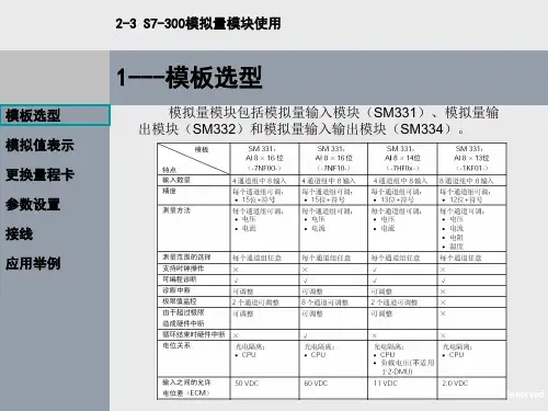
模拟量信号模块是一种用于采集、转换和传输模拟量信号的装置。
模拟量信号通常指连续变化的电压或电流信号,常见于各种传感器输出的信号,如压力、温度、流量等。
模拟量信号模块的主要作用是将这些模拟信号转换成计算机或其他控制器能够处理的数字信号,以便进行进一步的数据处理、分析和控制。
模拟量信号模块通常包括模拟量输入模块(AI模块)和模拟量输出模块(AO 模块)。
模拟量输入模块负责将外部传感器输出的模拟信号转换为数字信号,供计算机或控制器进行读取和处理。
模拟量输出模块则将计算机或控制器输出的数字信号转换为模拟信号,以驱动外部执行机构,如电机、阀门等。
模拟量信号模块广泛应用于工业自动化、环境监测、医疗设备等领域。
在工业自动化领域,模拟量信号模块可用于实现设备的远程监控和控制,提高生产效率和产品质量。
在环境监测领域,模拟量信号模块可用于采集和传输环境参数,如温度、湿度、气压等,为环境保护和气象预报提供数据支持。
在医疗设备领域,模拟量信号模块可用于监测患者的生理参数,如心电图、血压等,为医疗诊断和治疗提供依据。
总之,模拟量信号模块是工业自动化和控制系统中的重要组成部分,是实现数据采集、转换和传输的关键装置。

模拟量输入模块 AI2xSG 4/6 线制 HS使用入门7MH4134-6LB00-0DA0 / 测力模块、高速SiemensIndustryOnlineS i e m e n s c o p y r i g h t 2021 A l l r i g h t s r e s e r v e dThis entry is from the Siemens Industry Online Support. The general terms of use (/terms_of_use ) apply.Security informa-tionSiemens provides products and solutions with industrial security functions that support the secure operation of plants, systems, machines and networks. In order to protect plants, systems, machines and networks against cyber threats, it is necessary to implement – and continuously maintain – a holistic, state-of-the-art industrial security concept. Siemens’ products and solutions only form one element of such a concept.Customer is responsible to prevent unauthorized access to its plants, systems, machines and networks. Systems, machines and components should only be connected to the enterprise network or the internet if and to the extent necessary and with appropriate security measures (e.g. use of firewalls and network segmentation) in place.Additionally, Siemens’ guidance on appropriate security measures should be taken into account. For more information about industrial security, please visit /industrialsecurity .Siemens’ products and solutions undergo continuous development to make them more secure. Siemens strongly recommends to apply product updates as soon as available and to always use the latest product versions. Use of product versions that are no longer supported, and failure to apply latest updates may increase customer’s exposure to cyber threats.To stay informed about product updates, subscribe to the Siemens Industrial Security RSS Feed under /industrialsecurity .S i e m e n s c o p y r i g h t 2021 A l l r i g h t s r e s e r v e d目录1概述 ...................................................................................................................... 4 1.1 简介 ...................................................................................................... 4 1.2 参考文档 ............................................................................................... 4 1.3 主要概念和功能介绍 ............................................................................. 4 1.3.1 模块参数设置方法: ............................................................................. 4 1.3.2 采样方式 ............................................................................................... 4 1.3.3 滤波器 ................................................................................................... 5 1.3.4 输入锁定 ............................................................................................... 5 1.3.5 输入信号和模拟量数值对应关系 ........................................................... 5 1.3.6 输入范围的表示 .................................................................................... 6 1.3.7 地址空间 ............................................................................................... 6 2使用 (8)2.1 接线 ...................................................................................................... 8 2.2 参数设置 ............................................................................................... 8 2.2.1 通过硬件组态设置参数 ......................................................................... 8 2.2.2CPU 运行中设置参数 .......................................................................... 12 2.3 测量值读取 ......................................................................................... 12 2.4 模块控制 ............................................................................................. 13 2.5 细分采样使用 .. (13)S i e m e n s A G c o p y r i g h t 2021 A l l r i g h t s r e s e r v e d1概述1.1简介AI 2×SG 4/6线制 HS 模块是一款集成在ET200SP 中的测量力或力矩的模拟量输入模块,可以连接4线制或6线制的全桥应变片式传感器,具有两个模拟量输入通道,信号最小采样分辨率可以达到100μs 。