
蝶阀选型手册
- 格式:pdf
- 大小:312.88 KB
- 文档页数:4
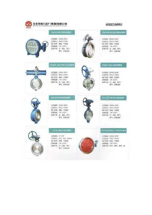

对夹( 单夹) 式蝶阀
使
用
说
明
书
中核苏阀科技实业股份有限公司
一.用途
本蝶阀适用于石油、化工、食品、医药、造纸、水电、船舶、供、排水、冶炼和能源等系统管路上, 可在多种腐蚀性、非腐蚀性气体、液体、半流体以及固体粉末管线和容器上为调节和截流设备使用。
二.性能规范
注: 适用温度和适用介质是根据不同阀座、阀体、阀板的材料配对而确定的, 见表1和表2:
主要零部件材质表1
阀座的性能表2
三.产品符合标准
1.该产品符合BS EN 593: 1984 《INDUSTRIAL VALVES-METALLIC BUTTERFLY VALVES》标
准要求。
2.法兰连接尺寸符合BS EN 1092-1、 BS EN 1092-2、 BS 4504: SECTION
3.3:1989《FLANGES
AND THEIR JOINTS-CIRCULAR F LANGES FOR PIPES, VALVES , FITTINGS AND ACCESSORIES,。

General• Size: 2”–12”• Outer Body: Glass-fi lled PP• Material: PVC, CPVC, PROGEF® Standard PP, ABS, SYGEF® Standard PVDF• Seals: EPDM, FPM, PTFE/FPM• Stem: 316 stainless steel• Voltage: 100-230VAC, 24VAC/DC• Connection: Both ANSI 150 and DIN 2501• Actuator Housing: Glass-fi lled PP• Manual Override: Integrated• End Stops: Open, close, programmable middle position• Position Indicator: LED, optical, integrated• Position Feedback: Open, close, middle• Heater: 10 position adjustable Specifi cationThe Type 145 Electrically Actuated Butterfl y Valve shall be wafer style compatible with both ANSI B16.5 150 lb and DIN 2501 fl ange patterns. The disk operation shall utilize double eccentric design principles. The shaft shall be non-wetted by a bushing assembly with double O-ring seals and fi xed at both ends. The face seal shall be a Q-ring compatible with fl at and serrated fl ange adapters. The face, disk and shaft seals shall operate independently. The wetted body and disk shall be of like materials. Valves shall be rated for bidirectional use. The operator mounting fl ange shall be comply with ISO standards. All valves shall be tested in accordance to ISO9393 and designed to ISO16136 standards. All valves shall be manufactured under ISO9001 for Quality and ISO14001 for Environmental Management. Following assembly, every valve shall be tested and certified bubble tight exceeding Class VI standards.2Electric ActuatorIntermediate KitType 567 Butterfl y ValveOptional Features• Positioner : Current, voltage • Network : Profi bus DP• Fail Safe Return : Battery back up, externally powered board • Smart Module : Cycle monitoring, cycle counter, cycle exten-sion, motor current monitoring• Manual Loading Station : Local control box • Protection Class : IP67 with conduit connection • Stem Extension : Two piece stainless steel • Shaft : Titanium, Hastelloy-C• Hardware : Alternatives available upon request • Cleaned : Silicone free/oil freeMaterial Specifi cationPVC valves shall meet ASTM D1784 cell classifi cation 12454 standards. CPVC valves shall meet ASTM D1784 cell classifi -cation 23447-B standards. PP valves shall meet ASTM D5847-14 cell classifi cation PP0510B66851 standards. ABS valves shall meet ASTM D3965 cell classifi cation 42222 standards. PVDF valves shall be type 1, grade 2 according to ASTM D3222 standards. Valves of all materials shall be RoHS compliant.Actuator Certifi cations/Compliance• Machinery Directive 2006/42/EC, Annex II B • EMV Directive CE 2004/108/CE • EMV VDE 0843 Section 20• Low Voltage Directive CE 2006/95/CE • Vibration Testing EN 60068-2-6• Interface ISO 5211• Actuators for Inustrial Valves EN 15714-2ComponentsKey Valve Certifi cations• NSF 61: PVC and CPVC• FDA CFR 21 177.1520: PP and PVDF • FDA CFR 21 177.2600: EPDM and FPM • FDA CFR 21 177.1550: PTFE • ABS : All materials• USP Class VI (physiological non-toxic): EPDM, FPM, PTFE,PP and PVDFActuator Technical Data(1) Overload protection of the motor is dimension e d so that the motor and the power supply board are protected. As soon as the load is within the torque range, the actuator will begin operating again.CPVC PVCPressure Temperature CurvesThe following graphs are based on a 25 year lifetime water or similar media applicationTechnical DataVacuum ServicePressure-TemperatureMaterial Temperature Range (ºF)Max Pressure (psi)PVC32 to 140150CPVC32 to 176 150PP32 to 176150ABS-40 to 140150PVDF-4 to 284150The Type 145 is rated for full vacuum service. Maximumdiff erential pressure of 15psi at 122ºF.45DimensionsThe following tables are shown in inches unless otherwise specifiedAll Materials without Manual Overrideinch d2 D D1 H H1 H2 H3 L L1 L2 L3 Q 1 Q 2 26.30.75 4.7515.71 3.03 5.287.4 1.77 4.87.09 6.5 1.57-2½7.090.75 5.516.18 3.27 5.517.4 1.81 4.87.097.17 2.13 1.3837.680.75616.65 3.5 5.757.4 1.93 4.87.098.27 2.64 1.9748.90.757.518.15 4.17 6.577.4 2.2 4.87.099.45 3.46 2.91510.160.98.519.29 4.767.137.4 2.52 4.87.0910.71 4.45 3.82611.180.99.520.08 5.247.447.4 2.83 4.87.0911.81 5.47 4.84813.430.911.7522.72 6.268.278.19 2.87 4.87.0914.177.01 6.651016.22 1.014.2526.658.0710.398.19 4.45 4.87.0917.328.278.151218.981.01728.629.2111.228.194.454.87.0920.0810.089.96GF Piping SystemsTel. (714) 731-8800, Toll Free (800) 854-4090, Fax (714) 731-6201us.ps @georgfi , #1334-54 (2/15)© 2015 Georg Fischer LLCPrinted in USAAll Materials with Manual Overrideinch d2 D D1 H H1 H2 H3 H4 L L1 L2 L3 L4 Q 1 Q 2 2 6.30.75 4.7515.71 3.03 5.287.4 2.36 1.77 4.87.09 6.57.87 1.57-2½7.090.75 5.516.18 3.27 5.517.4 2.36 1.81 4.87.097.177.87 2.13 1.3837.680.75616.65 3.5 5.757.4 2.36 1.93 4.87.098.277.87 2.64 1.9748.90.757.518.15 4.17 6.577.4 2.36 2.2 4.87.099.459.84 3.46 2.91510.160.98.519.29 4.767.137.4 2.36 2.52 4.87.0910.719.84 4.45 3.82611.180.99.520.08 5.247.447.4 2.36 2.83 4.87.0911.819.84 5.47 4.84813.430.911.7522.726.268.278.192.362.874.87.0914.179.847.016.65。
蝶阀使用说明书1.范围本说明书包括了公称通径DN50mm~1600mm(2”~64”)、公称压力PN1.0MPa~4.0MPa(ANSI CLASS150~300)法兰和对夹连接的手动、齿轮传动、电动和气动操作蝶阀。
2.用途2.1主要用于开启或关闭管道和设备的介质用,作调节、截流和止回使用。
2.2根据介质选用阀门的材质。
2.2.1碳钢阀门适用于水、蒸汽、油品等介质。
2.2.2不锈钢阀门适用于腐蚀性介质。
2.2.3铸铁阀门适用于水、气体介质。
2.3适用温度取决于阀座的材质。
PTFE(聚四氟乙烯)≤130℃不锈钢+复合体≤425℃橡胶≤85℃3.结构3.1蝶阀基本结构见图13.2易损件填料采用聚四氟乙烯或柔性石墨,密封可靠。
4.操作4.1手动操作阀门采用手柄或齿轮传动装置、电动或气动蝶阀由电动装置或气动装置驱动,使蝶板旋转90°开启或关闭阀门。
4.2对于手动(包括驱动装置的手轮)或扳手操作的蝶阀,除订货合同另有规定外,当面向手轮或扳手时,顺时针方向转动手轮或扳手阀门应为关。
4.3电动、气动蝶阀的开启、关闭指示由电动装置、气动装置上的位置指示器标识。
5.保管、保养、安装和使用5.1阀门应存放在干燥,通风的室内,阀门通道两端应堵塞。
5.2长期存放的阀门应定期检查,清除污物。
应特别注意密封面的清洁,防密封面的损坏。
5.3安装前应仔细核对阀门标志是否与使用要求相符。
5.4安装前应检查阀门通道和密封面,如有污垢,应使用清洁布擦拭干净。
5.5安装前检查填料是否压紧,应确保填料的密封性,同时不应妨碍阀杆的转动。
5.6安装时拧紧连接螺栓的拧紧力应均匀合适。
5.7本蝶阀可以安装水平、垂直的管道上,安装位置应保证使用维修更换方便。
5.8手动阀门在开启或关闭操作时,应使用手柄开、关,不得借用辅助杠杆或其它工具。
5.9阀门使用应定期检查,检查密封面有无磨损及垫片填料。
若损坏失效,应及时修理或更换。
5.10电动、气动阀门的传动装置,其保管、保养、安装和使用,请见“阀门电动装置使用说明书”及“阀门气动装置使用说明书”。

蝶阀使用说明书1.范围本说明书包括了公称通径DN50mm~1600mm(2”~64”)、公称压力PN1.0MPa~4.0MPa(ANSI CLASS150~300)法兰和对夹连接的手动、齿轮传动、电动和气动操作蝶阀。
矚慫润厲钐瘗睞枥庑赖賃軔。
2.用途2.1主要用于开启或关闭管道和设备的介质用,作调节、截流和止回使用。
2.2根据介质选用阀门的材质。
2.2.1碳钢阀门适用于水、蒸汽、油品等介质。
2.2.2不锈钢阀门适用于腐蚀性介质。
2.2.3铸铁阀门适用于水、气体介质。
2.3适用温度取决于阀座的材质。
PTFE(聚四氟乙烯)≤130℃不锈钢+复合体≤425℃橡胶≤85℃3.结构3.1蝶阀基本结构见图13.2易损件填料采用聚四氟乙烯或柔性石墨,密封可靠。
4.操作4.1手动操作阀门采用手柄或齿轮传动装置、电动或气动蝶阀由电动装置或气动装置驱动,使蝶板旋转90°开启或关闭阀门。
聞創沟燴鐺險爱氇谴净祸測。
4.2对于手动(包括驱动装置的手轮)或扳手操作的蝶阀,除订货合同另有规定外,当面向手轮或扳手时,顺时针方向转动手轮或扳手阀门应为关。
残骛楼諍锩瀨濟溆塹籟婭骒。
4.3电动、气动蝶阀的开启、关闭指示由电动装置、气动装置上的位置指示器标识。
5.保管、保养、安装和使用5.1阀门应存放在干燥,通风的室内,阀门通道两端应堵塞。
5.2长期存放的阀门应定期检查,清除污物。
应特别注意密封面的清洁,防密封面的损坏。
5.3安装前应仔细核对阀门标志是否与使用要求相符。
5.4安装前应检查阀门通道和密封面,如有污垢,应使用清洁布擦拭干净。
5.5安装前检查填料是否压紧,应确保填料的密封性,同时不应妨碍阀杆的转动。
5.6安装时拧紧连接螺栓的拧紧力应均匀合适。
5.7本蝶阀可以安装水平、垂直的管道上,安装位置应保证使用维修更换方便。
5.8手动阀门在开启或关闭操作时,应使用手柄开、关,不得借用辅助杠杆或其它工具。
5.9阀门使用应定期检查,检查密封面有无磨损及垫片填料。