DF9-40柔性薄膜压力传感器规格书
- 格式:pdf
- 大小:2.06 MB
- 文档页数:4

MLH SeriesAll Metal Pressure SensorsDESCRIPTIONMLH Series pressure sensors combine Application Specific Integrated Circuit (ASIC) technology with a media isolated, metal diaphragm design. This digitally compensated sensor offers value and performance, making it the ideal pressure sensing solution for demanding applications. Fully temperature compensated, calibrated and amplified, the MLH is available in 50 psi to 8,000 psi pressure ranges.MLH sensors deliver ±0.25% full scale accuracy Best Fit Straight Line (BFSL) and as low as 2% total error over a temperature range of -40 °C to 125 °C [-40 °F to 257 °F]. Industry standard connectors and process ports are offered for enhanced reliability and user flexibility.The MLH has seven standard output options:A. 0.5 Vdc to 4.5 Vdc ratiometric output from 5 Vdc excitationB. 4 mA to 20 mA current from 9.5 Vdc to 30 Vdc excitationC. 1.0 Vdc to 6.0 Vdc regulated output from 8 Vdc to30 Vdc excitationD. 0.25 Vdc to 10.25 Vdc regulated output from 14 Vdc to30 Vdc excitationE. 0.5 Vdc to 4.5 Vdc regulated output from 7 Vdc to30 Vdc excitationF. 0 mV to 50 mV from 5 Vdc excitationG. 1 Vdc to 5 Vdc output from 8 Vdc to 30 Vdc excitationFEATURES• All metal wetted parts for use in wide variety of fluidapplications• No internal elastomeric seals mean no o-ring compatibilityissues• Amplified outputs eliminate cost of external amplifiers • Input reverse voltage and output short circuit protectionsguard against mis-wiring• Less than 2 ms response time provides accurate, highspeed measurement• Rated IP65 or better for protection from harsh environmentsPOTENTIAL APPLICATIONS • Compressors• Refrigeration and HVAC/R • General industrial • General hydraulics• Multiple transportation applications including braking andalternate fuels • MedicalMLH Series2 /sensingTable 1. Pressure Range Specifications 1(At 25 °C [77 °F] and at rated excitation unless otherwise specified.)psiPressure 50 100 150 200 250 300 500 1000 2000 3000 5000 8000 Proof pressure 150 300 450 600 750 900 1500 2000 4000 6000 7500 12000 Burst pressure 500 1000 1500 2000 2500 3000 5000 10000 20000 30000 30000 30000barPressure 6 10 16 25 40 60 100 160 250 350 500 550 Proof pressure 18 30 48 75 80 120 200 320 500 700 750 825 Burst pressure60 100 160 250 400 600 1000 1600 2068 2068 2068 2068Note:1. Comparable metric units follow same proof and burst specifications.Table 2. Physical and Environmental SpecificationsParameter Characteristic Material in contact with media stainless steel 300 series and Haynes 214 alloy, Hastelloy C22 sensor available (contact factory) Housing material black plastic – Amodel AS-4133 HS – PPA Weight 57.0 g [2.0 oz] (typical for Packard MetriPak and 1/8 NPT port) Shock 100 g peak [11 ms] Vibration MIL-STD-810C, Figure 514.2-5, Curve AK, Table 514.2-V, Random Vibration Test [overall g rms =20.7 min.]Compensated, operating and storage temperature range-40 °C to 125 °C [-40 °F to 257 °F]Table 3. Electrical Specifications (At 25 °C [77 °F] and at rated excitation unless otherwise specified.) Parameter Ratiometric(A)1 Current (B) Regulated(C) Regulated(D) Regulated(E) mV (F) Regulated(G) Zero output 0.5 Vdc4.0 mA1.0 Vdc0.25 Vdc0.5 Vdc0 ±2.5 mV1.0 VdcFull scale span (FSS) 4.0 Vdc (0.5 to 4.5 Vdc) 16 mA (4 to 20 mA) 5.0 Vdc (1.0 to 6.0 Vdc) 10.0 Vdc (0.25 to 10.25 Vdc) 4.0 Vdc (0.5 to4.5 Vdc) 50 mV (0 to 50 mV) 4.0 Vdc (1.0 to 5.0 Vdc)Excitation 5 Vdc (6.0 Vdc max.) 9.5 Vdc to 30.0 Vdc 8.0 Vdc to 30.0 Vdc 14.0 Vdc to 30.0 Vdc 7.0 Vdc to 30.0 Vdc5.0 Vdc (6.0 Vdc max.)8.0 Vdc to 30.0 VdcSupply current 4.0 mA typical (8 mA max.)N/A 5.0 mA typical (17 mA max.)5.0 mA typical (17 mA max.)5.0 mA typical (17 mA max.) 8.0 mA typical (17 mA max.) 5.0 mA typical (17 mA max.)Source (nominal) 1.0 mA N/A 1.0 mA 1.0 mA 1.0 mA N/A 1.0 mA Sink(nominal) 1.0 mA at zero outputN/A 1.0 mA at zero output1.0 mA at zero output1.0 mA at zero outputN/A 1.0 mA at zero outputSupplyrejection ratio 90 db 90 db 90 db 90 db 90 db N/A90 dbOutput impedance25 Ω max.N/A25 Ω max.25 Ω max.25 Ω max.2000 Ω 25 Ω max.Note:1. Maintains ratiometricity at 5 ±0.25 Vdc excitation. Product can tolerate 6 Vdc excitation without damage.All Metal Pressure SensorsHoneywell Sensing and Control 3Table 4. Performance Specifications (At 25 °C [77 °F] and at rated excitation unless otherwise specified.)Parameter Characteristic Response time <2 msAccuracy 1:>100 psi<100 psi±0.25% FSS ±0.50% FSS Total error band 2:Gage:<300 psig>300 psigSeal gage:>300 psisSeal gage without L, M, P termination:100 psis to 299 psis (-40 °C to 85 °C [-40 °F to 185 °F])100 psis to 299 psis (>85 °C to 125 °C [>185 °F to 257 °F])>300 psis (-40 °C to 125 °C [-40 °F to 257 °F])Seal gage with L, M, P termination:100 psis to 299 psis (-40 °C to 65 °C [-40 °F to 149 °F])100 psis to 299 psis (>65 °C to 125 °C [>149 °F to 257 °F])>300 psis (-40 °C to 65 °C [-40 °F to 149 °F])>300 psis (>65 °C to 125 °C [>149 °F to 257 °F])±3% FSS ±2% FSS ±2% FSS ±3% FSS ±10% FSS ±2% FSS ±10% FSS ±15% FSS ±5% FSS ±15% FSS Notes:1. Includes pressure non-linearity (BFSL), pressure hysteresis and non-repeatability. Thermal errors are not included.2. Includes zero error, span error, thermal effect on zero, thermal effect on span, thermal hysteresis, pressure-non-linearity,pressure hysteresis and non-repeatability.1Sensing and Control Honeywell1985 Douglas Drive North Golden Valley, MN 55422 /sensing 008118-5-EN IL50 GLO Printed in USAJanuary 2009Copyright © 2009. Honeywell International Inc. All rights reserved.Figure 2. Mounting Dimensions (For reference only. mm/(in).)Pin and Wire Codes (Option B – Packard)Pin Voltage Current a + Excitation + Excitation b Output - Excitation c Common No ConnectionA variety of pressure ports and electricaltermination connection options are available. Refer to the “How to Order” on previous page for possible combinations. Contact your Honeywell representative for details.WARNINGMISUSE OF DOCUMENTATION• The information presented in this product sheet is forreference only. Do not use this document as a product installation guide.• Complete installation, operation, and maintenanceinformation is provided in the instructions supplied with each product.Failure to comply with these instructions could result in death or serious injury.WARRANTY/REMEDYHoneywell warrants goods of its manufacture as being free of defective materials and faulty workmanship. Honeywell’s standard product warranty applies unless agreed to otherwise by Honeywell in writing; please refer to your order acknowledgement or consult your local sales office for specific warranty details. If warranted goods are returned to Honeywell during the period of coverage, Honeywell will repair or replace, at its option, without charge those items it finds defective. Theforegoing is buyer’s sole remedy and is in lieu of all other warranties, expressed or implied, including those of merchantability and fitness for a particular purpose. In no event shall Honeywell be liable for consequential, special, or indirect damages.While we provide application assistance personally,through our literature and the Honeywell web site, it is up to the customer to determine the suitability of the product in the application.Specifications may change without notice. Theinformation we supply is believed to be accurate and reliable as of this printing. However, we assume no responsibility for its use.WARNINGPERSONAL INJURYDO NOT USE these products as safety or emergency stop devices or in any other application where failure of the product could result in personal injury.Failure to comply with these instructions could result in death or serious injury.SALES AND SERVICEHoneywell serves its customers through a worldwide network of sales offices, representatives and distributors. For application assistance, current specifications, pricing or name of the nearest Authorized Distributor, contact your local sales office or:E-mail:*********************Internet: /sensingPhone and Fax: Asia Pacific +65 6355-2828 +65 6445-3033 Fax Europe +44 (0) 1698 481481 +44 (0) 1698 481676 Fax Latin America +1-305-805-8188 +1-305-883-8257 F ax USA/Canada +1-800-537-6945 +1-815-235-6847 +1-815-235-6545 F ax。
GPD3压力传感器使用说明书煤炭科学研究总院沈阳研究院2010年5月第1版GPD3压力传感器使用说明书1、概述1.1产品特点本传感器采用精密压力敏感元件,可实现自动温度补偿,可以避免因温度变化引起的测量误差。
为尽量避免由外围元器件漂移引起的误差,所以采用很少的外围处理电路。
传感器结构简单,功能强大。
可以测量正压、负压、及压差。
1.2用途及适用范围1.2.1用于测量煤矿井下通风巷道压力。
1.2.2瓦斯抽放管道等有甲烷和煤尘爆炸危险环境的压力。
1.3型号含义1.4使用环境条件工作环境应避免淋水。
1.5工作条件1.5.1环境温度:0~40℃1.5.2相对湿度:≤98%(25℃时) 1.5.3大气压力:80~110 kPa2、安全特征2.1本传感器为矿用本质安全型。
2.2防爆标志为:Exib Ⅰ。
2、结构及工作原理图1:GY3压力传感器外型示意图G P D 3主参数:测量范围0~3.0kPa 主参数:测量范围 产品特征代号:压力差式 产品类别代号:传感器3、技术特征3.1测量范围:0~3.00kPa3.2供电电源:12~21VDC3.3电流:≤70mA3.4供电距离:1500m(电缆截面为0.43m㎡)3.5输出频率信号:200~1000Hz (负载≤600Ω)4、尺寸及重量4.1仪器外型尺寸(mm):210×130×554.2重量(kg):25、安装、调试5.1、本传感器可挂在煤矿井下需要检测压力的地方,使用时垂直悬挂。
5.2、传感器连接电缆,电缆选用四芯型矿用阻燃电缆,传感器三根引出线接法为:5.3、测量负压时,接右侧,测量取压管可选用PU管或橡胶管;当有一个取压嘴时,既可以测量正压,也可以测量负压。
注意:(1)安装取压管时,不得使传感器取压嘴的压力,超过传感器测量最大值的3倍。
(2)当有两个取压嘴时,不得用负压嘴测量正压。
5.4、电缆取压管连接无误后,给传感器送电,10秒后传感器进入稳定测量,显示所测压力的数值。
电应普超声波传感器规格书全文共四篇示例,供读者参考第一篇示例:电应普超声波传感器规格书一、产品概述电应普超声波传感器是一种先进的传感器,通过发射和接收超声波来测量物体与传感器之间的距离。
它具有高精度、高稳定性和高可靠性的特点,广泛应用于工业自动化、智能家居、智能车载等领域。
二、技术参数1. 工作频率:40kHz2. 测量范围:0.2m-5m3. 分辨率:1mm4. 工作温度:-20℃~70℃5. 输出方式:模拟电压信号/数字信号6. 工作电压:5V7. 防护等级:IP678. 重复性误差:±1mm9. 防干扰能力:工业级10. 尺寸:Φ16mm*75mm三、产品特点1. 高精度:采用先进的超声波技术,测量精度高达1mm,满足各种精密测量需求。
2. 高稳定性:具有优异的稳定性,工作过程中不受外界干扰影响,保证测量结果准确可靠。
3. 高可靠性:采用优质材料和先进工艺制造,具有长期稳定的性能和使用寿命。
4. 多种输出方式:可选模拟电压信号输出或数字信号输出,适用于不同的应用场景。
5. 强大的防干扰能力:具有工业级防干扰能力,可在复杂的电磁环境下稳定工作。
6. 小巧的尺寸:体积小巧,安装方便,适用于各种空间有限的场合。
四、应用领域电应普超声波传感器广泛应用于以下领域:1. 工业自动化:用于机器人、流水线等设备的距离测量和障碍检测。
2. 智能家居:用于智能门锁、智能照明等设备的距离控制和智能化操作。
3. 智能车载:用于车载倒车雷达、车位检测等系统的距离测量和安全预警。
4. 仓储物流:用于货架高度检测、自动导航车的导航等应用。
第二篇示例:电应普超声波传感器规格书一、产品概述电应普超声波传感器是一种广泛应用于测距、检测和定位的传感器,它利用声音的反射原理来实现测距和探测物体的目的。
本传感器具有高精度、快速响应、稳定性好等特点,能够适用于各种工业自动化领域。
二、产品特点1. 采用电应普最新一代超声波传感技术,性能稳定可靠。

霍尼韦尔压力传感器型号霍尼韦尔压力传感器 142PC01D,142PC02D,142PC03D,142PC05D,142PC15D,142PC30D,142PC15A,142PC30A,142PC30G,141PC01D,141PC02D,141PC03D,141PC05D,141PC15D,141PC30D,143PC01D,143PC02D,143PC03D,143PC05D,143PC15D,143PC30D,141PC01G,141PC02G,141PC05G,142PC01G,142PC02G,142PC03G,142PC05G,142PC15G,163PC01D36,163PC01D48,163PC01D75,164PC01D76,163PC01D37,163PC01D76,161PC01D36,162PC01D36,164PC01D36,189PC15GM,189PC100GM,189PC150GM,ASCX01DN,ASCX05DN,ASCX15AN,ASCX15DN,ASCX30AN,ASCX30DN,ASCX100AN,ASCX100DN,ASCX150DN,ASCX150AN,ASDX015A24R,ASDX030A24R,ASDX100A24R,ASDX001G24R,ASDX005G24R,ASDX015G24R,ASDX020G24R,ASDX100G44R,ASDX001D44R,ASDX005D44R,ASDX015D44R,ASDX030D44R,ASDX100D44R,40PC001G2A, 40PC015G2A, 40PC100G2A, 40PC150G2A, 40PC250G2A, 40PC500G2A, 4040 PC001G2A, 4040PC015G2A, 4040PC100G2 A, 4040PC150G2A, 4040PC250G2A, 4040PC500G2A. 微压传感器 CPCL04DC,CPCL10DC,CPCL04DTC,CPCL10DTC,CPXL04DTC,CPXL10DTC,CPXL01DC,CPXL10DC,XPCL04DC,XPCL10DC,XPCL04DTC,XPCL10DTC,XPX50D,XPXL04DC,XPXL10DC,XPXL04DTC,XPXL10DTC,XSXL04D,XSXL10D,XSCL04DC,XSCL10DC,SDXL005D4,SDXL010D,SLP004D,SLP010D,DCXL01DN,DCXL05DN,DCXL10DN,DCXL20DN,DCXL30DN,DC001NDC4,DC002NDC4,DC005NDC4,DC010NDC4,DC020NDC4,DC030NDC4,DC001NDR4,DC002NDR4,DC005NDR4,DC010NDR4,DC020NDR4,DC030NDR4,DC001NDR5,DC002NDR5,DC005NDR5,DC010NDR5,DC020NDR5,DC030NDR5,DC2R5BDC4,DC005BDC4,DC075BDC4,DUXL01D,DUXL05D,DUXL10D,DUXL20D,DUXL30D。
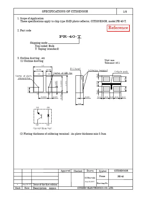
9. Precautions 9-1. Soldering(1) Manual Soldering1) Solder with silver content is recommended.2) As to CITISENSORs that have absorbed moisture by any chance, baking isrecommended prior or the soldering process to prevent CITISENSORs from the possible crack problem due to the absorbed moisture.3) The use of the soldering iron in less than 25W and the temperature of iron tip must be kept at no higher than 350°C.4) Force or stress must not be applied to the resin portion while soldering. 5) It is requested to solder each land within 3 seconds.6) It is requested that products should be handled after their temperature has dropped down to the normal room temperature.(2) Reflow soldering1) Following soldering paste is recommended Melting temperature: 178 ~ 192°C. Composition: Sn 63 %, Pb 37 %2) The temperature profile at the top surface of the parts is recommended as shown below.3) It is requested that products should be handled after their temperature has dropped down to the normal room temperature.(3) Lead free soldering1) Following soldering paste is recommended Melting temperature: 216 ~ 220°C.Composition: Sn 3.5Ag 0.75Cu2) The temperature profile at the top surface of the parts is recommended as shown below.3) It is requested that products should be handled after their temperature has dropped down to the normal room temperature.Reflow soldering of the above profile is allowed two times.ApprovedCheckedDrawnSymbol CITISENSORNamePR-40140~160°C4°C sec.Max10sec.Max240°C Max More than 1min.T e m p e r a t u r eTime4°C /sec.Max140sec160~180°C4°C /sec.MaxT e m p e r a t u r eTime4°C /sec.Max260°C Max 220°C60~70secReferenceAug.22,2007M.Okuwaki9-2. CleaningPerform the cleaning after soldering strictly in conformity to the following conditions:· Cleaning Agent : Alcohol· Temperature and Time: 30 seconds under the temperature below 50°C or 3 minutes below 30°C.· Ultrasonic Cleaning : 300W or less9-3. Other Precaution1) It is requested to avoid any stress added to the resin portion while heating.2) It is requested to avoid any friction by sharp metal nail etc. to the resin portion. 10. Precautions on Designing1) The Current limiting Resistor should be placed on the circuit to drive within the rating. Also the design should be done to avoid the reverse voltage (over-current) applied instantaneously when turned ON or OFF .2) When the Pulse Driving Current is applied, the average current consumptionshould be within the rating. Also the design should be done to avoid the reverse voltage applied when put off.3) Recommended Soldering Pattern<For Reflow Soldering>The above dimensions are recommended,but the mountability study should be conducted in advance at your site.4) When assembling the circuit board into the finished products, pay attention to avoid the component parts from touching with other parts.ApprovedChecked DrawnSymbol CITISENSORNamePR-40ReferenceAug.22,2007M.Okuwaki0.60.60.60.60.30.375。
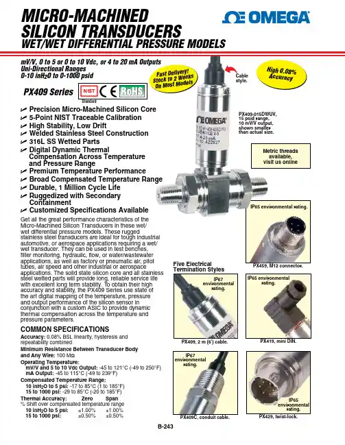
common SPEcIFIcATIonSAccuracy: 0.08% BSL linearity, hysteresis and repeatability combinedminimum Resistance Between Transducer Body and Any Wire: 100 M Ωoperating Temperature:mV/V and 5 to 10 Vdc output: -45 to 121°C (-49 to 250°F) mA output: -45 to 115°C (-49 to 239°F) compensated Temperature Range:10 inH 2o to 5 psi: -17 to 85°C (1 to 185°F) 15 to 1000 psi: -29 to 85°C (-20 to 185°F)Thermal Accuracy: Zero Span % Shift over compensated temperature range mV/V, 0 to 5 or 0 to 10 Vdc, or 4 to 20 ma outputs 0-10 inh 2U P recision micro-machined Silicon core U 5-Point nIST Traceable calibration U H igh Stability, Low Drift U W elded Stainless Steel construction U 316L SS Wetted Parts U Digital Dynamic Thermalcompensation Across Temperature and Pressure Range U P remium Temperature Performance U B road compensated Temperature Range U D urable, 1 million cycle Life U R uggedized with Secondary containment U c ustomized Specifications AvailableGet all the great performance characteristics of the Micro-Machined Silicon Transducers in these wet/wet differential pressure models. These ruggedstainless steel transducers are ideal for tough industrial automotive, or aerospace applications requiring a wet/wet transducer. They can be used in test benches, filter monitoring, hydraulic, flow, or water/wastewater applications, as well as factory or pneumatic air, pitot tubes, air speed and other industrial or aerospaceapplications. The solid state silicon core and all stainless steel wetted parts will provide long, reliable service life with excellent long term stability. T o obtain their high accuracy and stability, the PX409 Series use state of the art digital mapping of the temperature, pressure and output performance of the silicon sensor in conjunction with a custom ASIC to provide dynamic thermal compensation across the temperature and pressure parameters.Five Electrical Termination StylesPX409, 2 m (6') cable.IP67environmentalrating.IP67environmentalrating.IP65 environmentalrating.IP65environmentalPX419, mini DIn.IP65 environmental rating.PX459, m12 connector.PX409 SeriesPX409-015DWUV, 15 psid range, 10 mV/V output, shown smaller than actual size.f a s t d e l i v e r y !S t o c k t o 2 we e k s o n M o s t Mo d e l s h i g h 0.08%a c c u r a c y metric threads available, visit us onlinecable style.UnI-DIREcTIonAL mV/V SPEcIFIcATIonSoutput: 10 mV/V ratiometricSupply Voltage:5 to 10 Vdc current Draw: 5 mA @ 10 Vdc Input Impedance: 1000 to 5000 Ωoutput Impedance: 5000 Ω ±10% typical Zero Balance: Ranges ≤ 2.5psi: ±1% typical (2% maximum) Ranges > 2.5psi: ±0.5% typical (1% maximum)Span Setting: Ordering Examples: PX409-100DWUV, 0 to 100 psi uni-directional wet/wet differential pressure range, 10 mV/V output, 0.08% accuracy, 1⁄4 NPT fittings, 2 m (6') cable.PX419-015DWUV, 0 to 15 psi uni-directional wet/wet differential pressure range, 10 mV/V output, 0.08% accuracy, 1⁄4 NPT fittings, mini DIN connector.PX429-10WDWUV, 0 to 10 inH 2O uni-directional wet/wet differential pressure range, 10 mV/V output, 0.08% accuracy, 1⁄4 NPT fittings, twist-lock connector plus PT06F10-6S, mating connector.PX409-030DWUV, 30 psid range, 10 mV/V output, shown smaller than actual size.f a s t d e l i v e r y !S t o c k t o 2 we e k so n M o s t Mo d e l s cable style.[*] Enter “5” for PX459 M12 connector or “2” for PX429 twist lock connector (mating PX429 connector sold separately).metric threads available, visit usonlinef a s td e l i v e S t o c k t o 2 w e o n M o s t M o d mini DIn style.metric threads available, visit us onlinePX419-100DWU5V, 100 psid range, 0 to 5 Vdcoutput shown smaller than actual size.weT/weT differenTialPreSSure ModelS uni-direcTionalrangeS wiTh 4 to 20 ma ouTPuTSUnI-DIREcTIonALmA SPEcIFIcATIonSoutput: 4 to 20 mASupply Voltage:9 to 30 Vdc;[9 to 20 Vdc above 105°C (229°F)]max Loop Resistance: (Vs-9) x 50 Ω Zero Balance:Ranges > 2.5psi: ±0.5% typical (1% maximum) Ranges ≤ 2.5psi: ±1% typical (2% maximum)Span Setting:Ordering Examples: PX409-100DWUI, 0 to 100 psi uni-directional wet/wet differential pressure range, 4 to 20 mA output, 0.08% accuracy, 1⁄4 NPT fittings, 2 m (6') cable.PX419-015DWUI, 0 to 15 psi uni-directional wet/wet differential pressure range, 4 to 20 mA output, 0.08% accuracy, 1⁄4 NPT fittings, mini DIN connector.PX429-10WDWUI, 0 to 10 inH 2O uni-directional wet/wet differential pressure range, 4 to 20 mA output, 0.08% accuracy, 1⁄4 NPT fittings, twist-lock connector plus PT06F10-6S, mating connector.f a s t d e l i v e r y !S t o c k t o 2 we e k so n M o s t Mo d e l s PX429-005DWUI, 5 psid range, 4 to 20 mA output, shown smaller thanactual size.Twist-lock style.metric threads available, visit us online[*] Enter “5” for PX459 M12 connector or “2” for PX429 twist lock connector (mating PX429 connector sold separately).。
高精度电流传感器规格书RIT 01深圳市航智精密电子有限公司RIT01 剩余电流传感器多点零磁通技术系统应用于现有高精度直流传感器技术之上,激励磁通闭环控制技术、自激磁通门技术及多闭环控制技术相结合,实现了对激励磁通、直流磁通、交流磁通的零磁通闭环控制,并通过构建高频纹波感应通道实现了对高频纹波的检测,从而使传感器在全带宽范围内拥有比较高的增益和测量精度。
产品图片核心技术性能特点◇激励磁通闭环控制技术◇原、副边隔离测量◇自激退磁技术◇出色的线性度和准确度◇多点零磁通技术◇极低的温漂◇多级量程自动切换技术◇极低的零漂◇温控补偿技术◇强抗电磁干扰能力◇宽频带和低响应时间应用领域◇工业控制◇医疗设备◇铁路◇电力、电网◇电测仪器仪表◇新能源电气性能项目符号测试条件最小值标称最大值单位原边额定电流I PN—0 0.1 — A 原边过载电流I P——200% I PN— A 工作电压V C—±14.2 ±15 ±15.8 V 功耗电流I PWR—±30 mA 输出电压V SN0 ±2 —V精度测量项目符号测试条件最小值标称最大值单位精准度X G输入直流,额定量程——0.2 % 线性度εL全范围——0.2 % 零点电压I OT全温度范围——±10 mV 反应时间t r上升至90%I PN—— 2 us 频带宽度(-3dB) F —0 —100 kHz安全特性项目符号测试条件数值单位隔离电压/ 原边与副边之间Vd 50Hz,1min 5 KV瞬态隔离耐压/ 原边与副边之间Vw 50us 10 KV爬电距离/ 原边与外壳之间dCp —11 mm电气间隙距离/ 原边与外壳之间dCi —11 mm 相比漏电起痕指数CTI IEC-60112 275 V一般特性项目符号测试条件最小标称最大单位工作温度范围T A—-40 —+85 ºC存储温度范围T S—-55 —+95 ºC相对湿度RH —20 80 —质量M ——350±10 —g运行状态说明◇正常运行时,绿灯常亮:设备上电后,当设备正常工作时,绿色指示灯常亮,D-Sub9接口的第3脚和第8脚导通。
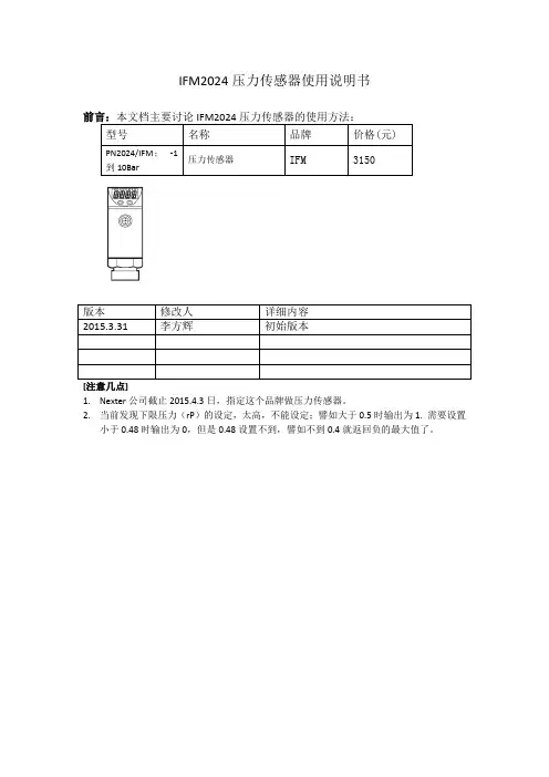
IFM2024压力传感器使用说明书
[注意几点]
1.Nexter公司截止2015.4.3日,指定这个品牌做压力传感器。
2.当前发现下限压力(rP)的设定,太高,不能设定;譬如大于0.5时输出为1. 需要设置
小于0.48时输出为0,但是0.48设置不到,譬如不到0.4就返回负的最大值了。
一、IFM2024按钮说明 (3)
1.1按钮说明 (3)
1.2.参数的修改: (4)
1.3.输出接线 (4)
1.4.参数设置锁定 (5)
一、IFM2024按钮说明
1.1 按钮说明
7—Output2输出指示;8 – Output1输出显示10:Set: 修改参数的值。
11:Mode/Enter: 选择参数、确认参数的修改。
按键顺序如下图:
1.持续按”Mode/Enter”,直到需要修改的参数出现。
2.一直按着”Set”按钮,当前参数值会闪烁5秒,5秒后参数值开始后改变,增加。
如果需要该值变小,那么需要按着该按钮,值增大到最大后,会从最小值开始。
3.按”Mode/Enter”,然后该值的修改就被确认下来。
1.3.输出接线
对于输出,我们一般设置一个SP,一个rP,大于SP时,输出为1,小于rP时,输出为0。
即(Hno模式)。
对于Output1,出厂默认就是这个模式,
参数设置完毕后,可以锁定参数的调整,锁定方法如下:
同时按” Mode/Enter”及”Set”键超过15秒,进行锁定或解锁。
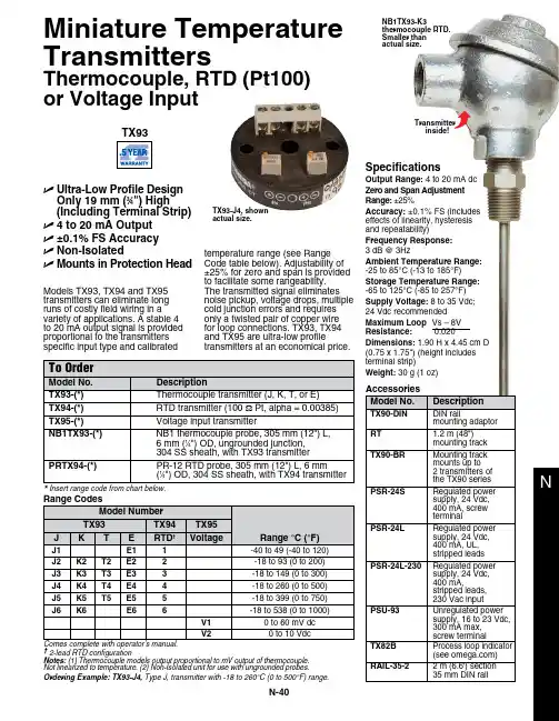
N-40NModels TX93, TX94 and TX95 transmitters can eliminate long runs of costly field wiring in a variety of applications. A stable 4 to 20 mA output signal is provided proportional to the transmitters specific input type and calibratedtemperature range (see Range Code table below). Adjustability of ±25% for zero and span is provided to facilitate some rangeability. The transmitted signal eliminates noise pickup, voltage drops, multiple cold junction errors and requires only a twisted pair of copper wire for loop connections. TX93, TX94 and TX95 are ultra-low profiletransmitters at an economical price.U Ultra-Low Profile Design Only 19 mm (3⁄4") High (Including Terminal Strip)U 4 to 20 mA Output U ±0.1% FS Accuracy U Non-IsolatedU Mounts in Protection HeadInsert range code from chart below.TX93-J4, shown actual size.Transmitter inside!Miniature Temperature Transmitters† 2-lead RTD configurationNotes: (1) Thermocouple models output proportional to mV output of thermocouple. Not linearized to temperature. (2) Non-Isolated unit for use with ungrounded probes.Ordering Example: TX93-J4, Type J, transmitter with -18 to 260°C (0 to 500°F) range.SpecificationsOutput Range: 4 to 20 mA dc Zero and Span Adjustment Range: ±25%Accuracy: ±0.1% FS (includes effects of linearity, hysteresis and repeatability)Frequency Response: 3 dB @ 3HzAmbient Temperature Range: -25 to 85°C (-13 to 185°F)Storage Temperature Range:-65 to 125°C (-85 to 257°F)Supply Voltage: 8 to 35 Vdc; 24 Vdc recommended Maximum Loop Vs – 8V Resistance: 0.020Dimensions: 1.90 H x 4.45 cm D (0.75 x 1.75") (height includes terminal strip)Weight: 30 g (1 oz)NB1TX93-K3thermocouple RTD. Smaller than actual size.Thermocouple, RTD (Pt100) or Voltage Input。
页次 1-11实业有限公司版次 1.0产品规格书日期 2013.目 录名 称 页 次目录 (1)产品图纸 (2)产品性能 (3)R-T表 (4)变更记录版次 变更日期 变更内容第1页 共11页24mm*0.31铜带热敏电阻备 注比 例重 量第 2 页图 样 标 记共 11 页名 称材 料 及 规 格温度传感器日期更改文件号签字数量实业有限公司1序号设计(审核)(工艺)处数标注23技术要求:1.表面光滑无毛剌;2.端子与导线连接紧固;4导线1铁氟龙管1 L铁氟龙管 mm 2客户确认56连接器端子C3-2Y白色C31271外胶内纤管 4 ∅L=90mm电子实业有限公司规格书R25℃=XXXKΩ±1% 页码:第3页共11页NTC负温度系数热敏电阻B25/50=XXX±1% 1.电气性能项目技术要求测试条件/测试方法测试仪器1.1 额定零功率电阻R25℃=100KΩ±2%环境温度范围25℃±0.1%放2小时测试仪表精度≤±0.2%测试功率≤±0.2mW1.2 B值B25/50=3950±1%B=Ln(R25/R50)/(1/273.15+50)-1/(273.15+25)环境温度: 25℃±0.1℃. 50℃±0.1℃测试仪表精度; ≤±0.2%1.恒温油槽宁波2. 水银温度计(北京玻璃研究院)3. LCR数字电桥1.3 耐压1500VDC/0.5mA.10S无击穿或飞弧现象耐压测试仪(南京长盛)1.4 绝缘电阻≥100ΜΩ/500VDC绝缘电阻测试仪(常州惠发电子有限公司)1.5 耗散系数δmax2.5mw/℃(静止空气中)δ=W/(T-T0)=l²R/(T-T0)1.6 时间常数τmax 10S (静止空气中)零功率状态下由一个特定温度向另一个特定温度突变时阻值变化63.2%所需时间1.7 工作温度-20℃--+200℃1.8 最大功率Pmax 5mw2.可靠性2.1 高温存放200℃环境中放置1000小时阻值变化不大于±2% 101-1型恒温干燥箱(设备有限公司)2.2 低温存放-20℃环境中放置1000小时阻值变化不大于±冰箱2.3 耐温热60℃95%RH存放1000小时阻值变化不大于±2%2.4 耐温度冲击-20℃30分钟—常温5分钟—70℃30分钟循环冲击3次后,阻值变化不大于±2%.101-1型恒温干燥箱(上海沪越实验设备有限公司)BCD-232容声冰箱2.5 引线强度引线沿轴向施加20N拉力并持续60S后,外观无损伤.阻值变化不大于±1%SLJ型拉力计(温州山度)VD9806型数字万用表2.6 振动元件经受加速10g,振幅1.5mm频率从10HZ到500HZ X.Y方向各15分钟后应无损伤,阻值变化不大于±2%VD9806型数字万用表2.7使用寿命正常使用电阻值年飘移率≤3‰3.其它性能3.1 外观无可见性损伤目测4.使用环境条件相对湿度: ≤±95%HK 振动频率: 10—500HZ 大气压力:40Kpa 加速度: 250m/S 贮存温度: -5℃--40℃R25=100KΩ 精度:±1% B25/50=3950K B25/85=4092K 精度:±1%(P182-6B2) 电阻(KΩ) 电阻精度(%) 温度精度(℃)温度(℃) 最小值 中心值 最大值 △R -△R △T -△T -55 20623.500 21986.100 23436.400 6.596 -6.197 0.715 -0.672 -54 17809.100 18957.600 20178.200 6.438 -6.058 0.712 -0.670 -53 15466.500 16440.600 17474.200 6.287 -5.924 0.709 -0.668 -52 13504.600 14335.400 15215.800 6.141 -5.795 0.706 -0.666 -51 11851.500 12564.000 13318.100 6.001 -5.671 0.703 -0.664 -50 10450.700 11064.900 11714.100 5.867 -5.551 0.699 -0.662 -49 9257.290 9789.400 10351.000 5.737 -5.435 0.696 -0.659 -48 8235.230 8698.310 9186.510 5.612 -5.323 0.692 -0.657 -47 7355.590 7760.350 8186.560 5.492 -5.215 0.689 -0.654 -46 6594.960 6950.200 7323.840 5.375 -5.111 0.685 -0.651 -45 5934.270 6247.250 6576.080 5.263 -5.009 0.681 -0.649 -44 5357.900 5634.670 5925.140 5.155 -4.911 0.678 -0.646 -43 4853.030 5098.620 5356.100 5.049 -4.816 0.674 -0.643 -42 4409.040 4627.670 4856.660 4.948 -4.724 0.670 -0.639 -41 4017.110 4212.340 4416.620 4.849 -4.634 0.666 -0.636 -40 3669.900 3844.740 4027.520 4.753 -4.547 0.662 -0.633 -39 3361.230 3518.250 3682.230 4.660 -4.462 0.657 -0.630 -38 3085.930 3227.300 3374.810 4.570 -4.380 0.653 -0.626 -37 2839.610 2967.200 3100.210 4.482 -4.300 0.649 -0.622 -36 2618.550 2733.970 2854.190 4.397 -4.221 0.644 -0.619 -35 2419.590 2524.220 2633.120 4.314 -4.145 0.640 -0.615 -34 2240.020 2335.070 2433.910 4.232 -4.070 0.635 -0.611 -33 2077.520 2164.020 2253.910 4.153 -3.997 0.631 -0.607-32 1930.090 2008.970 2090.850 4.076 -3.926 0.626 -0.603 -31 1796.020 1868.050 1942.780 4.000 -3.856 0.621 -0.599 -30 1673.800 1739.690 1808.000 3.926 -3.787 0.616 -0.594 -29 1562.140 1622.510 1685.040 3.854 -3.720 0.611 -0.590 -28 1459.910 1515.290 1572.610 3.783 -3.654 0.606 -0.585 -27 1366.120 1417.000 1469.610 3.713 -3.590 0.601 -0.581 -26 1279.910 1326.700 1375.060 3.645 -3.526 0.596 -0.576 -25 1200.520 1243.600 1288.100 3.578 -3.464 0.590 -0.571 -24 1127.280 1166.990 1207.980 3.512 -3.402 0.585 -0.567 -23 1059.590 1096.230 1134.020 3.447 -3.342 0.579 -0.562 -22 996.936 1030.770 1065.650 3.383 -3.282 0.574 -0.557 -21 938.848 970.126 1002.340 3.321 -3.224 0.568 -0.552 -20 884.914 913.850 943.637 3.259 -3.166 0.562 -0.546 -19 834.767 861.555 889.114 3.198 -3.109 0.557 -0.541 -18 788.078 812.895 838.409 3.138 -3.052 0.551 -0.536 -17 744.551 767.557 791.194 3.079 -2.997 0.545 -0.530R---T分度表 :- 传真:- 地址:15座4楼 网址:www..com 电子邮箱:@.comR25=100KΩ 精度:±1% B25/50=3950K B25/85=4092K 精度:±1%(P182-6B2) 电阻(KΩ) 电阻精度(%) 温度精度(℃)温度(℃) 最小值 中心值 最大值 △R -△R △T -△T -16 703.923 725.262 747.173 3.021 -2.942 0.539 -0.525 -15 665.955 685.759 706.082 2.963 -2.887 0.533 -0.519 -14 630.435 648.823 667.681 2.906 -2.834 0.526 -0.513 -13 597.168 614.249 631.756 2.850 -2.780 0.520 -0.507 -12 565.979 581.853 598.112 2.794 -2.728 0.514 -0.502 -11 536.711 551.468 566.575 2.739 -2.675 0.507 -0.496 -10 509.220 522.943 536.983 2.684 -2.624 0.501 -0.490 -9 483.374 496.140 509.192 2.630 -2.573 0.494 -0.483 -8 459.056 470.934 483.071 2.577 -2.522 0.488 -0.477 -7 436.156 447.211 458.499 2.524 -2.471 0.481 -0.471 -6 414.576 424.866 435.367 2.471 -2.421 0.474 -0.465 -5 394.224 403.803 413.574 2.419 -2.372 0.467 -0.458 -4 375.018 383.937 393.028 2.367 -2.322 0.460 -0.452 -3 356.881 365.185 373.645 2.316 -2.274 0.453 -0.445 -2 339.742 347.475 355.348 2.265 -2.225 0.446 -0.438 -1 323.538 330.738 338.065 2.215 -2.177 0.439 -0.431 0 308.207 314.913 321.731 2.165 -2.129 0.432 -0.425 1 293.697 299.940 306.285 2.115 -2.081 0.425 -0.418 2 279.954 285.767 291.671 2.066 -2.034 0.417 -0.411 3 266.934 272.345 277.838 2.017 -1.986 0.410 -0.404 4 254.590 259.627 264.737 1.968 -1.940 0.402 -0.396 5 242.884 247.572 252.325 1.919 -1.893 0.395 -0.389 6 231.778 236.139 240.559 1.871 -1.847 0.387 -0.382 7 221.236 225.293 229.402 1.823 -1.800 0.379 -0.374 8 211.226 214.999 218.817 1.776 -1.754 0.371 -0.367 9 201.717 205.225 208.772 1.728 -1.709 0.364 -0.359 10 192.681 195.941 199.236 1.681 -1.663 0.356 -0.352 11 184.092 187.121 190.180 1.634 -1.618 0.348 -0.344 12 175.925 178.737 181.576 1.588 -1.573 0.340 -0.336 13 168.157 170.767 173.400 1.541 -1.528 0.331 -0.328 14 160.766 163.187 165.628 1.495 -1.483 0.323 -0.320 15 153.731 155.976 158.237 1.449 -1.439 0.315 -0.312 16 147.034 149.114 151.208 1.404 -1.394 0.306 -0.304 17 140.657 142.582 144.520 1.358 -1.350 0.298 -0.296 18 134.582 136.364 138.155 1.313 -1.306 0.289 -0.287 19 128.794 130.442 132.097 1.268 -1.262 0.280 -0.279 20 123.279 124.800 126.328 1.224 -1.219 0.271 -0.270 21 118.021 119.425 120.834 1.179 -1.175 0.262 -0.261 22 113.009 114.303 115.600 1.135 -1.132 0.252 -0.251 23 108.229 109.420 110.614 1.090 -1.089 0.240 -0.240R---T分度表 :- 传真:- 地址:15座4楼 网址:www..com 电子邮箱:@.com。
电阻式压力传感器用户使用说明书V1.0深圳市中科鸥鹏智能科技有限公司2010年11月目录1.简介 (3)2.技术参数 (3)3.注意事项 (4)4.安装方法及软件 (5)1.简介FSR402是著名Interlink Electronics 公司生产的一款重量轻,体积小,感测精度高,超薄型电阻式压力传感器。
这款压力传感器是将施加在FSR传感器薄膜区域的压力转换成电阻值的变化,从而获得压力信息。
压力越大,电阻越低。
其允许用在压力100g-10kg的场合。
可用于机械夹持器末端感测有无夹持物品,仿生机器人足下地面感测,哺乳类动物咬力测试生物实验,应用范围及其广泛。
但是由于压力检测不是非常精确,因此不建议使用需要精确检测压力的场合。
2.技术参数●工作电压:5VDC@165mA●传感器感应面积:直径12.7mm●传感器类型:被动式可变电阻●压力感应范围:100g ~ 10 kg●使用寿命:>100万次挤压图1压力感应电阻是弯曲压力传感器的一种,简称FSR,FSR是一种随着有效表面上压力增大而输出阻值减小的高分子薄膜,FSR并不是测压元件或形变测量仪,尽管他们有着相似的性能。
而且这类压力感测电阻不适用于精密测量,但是FSR却是一款灵敏度较高的传感器。
图2图3这是它的性能曲线3.注意事项FSR的厚度为0.2mm—1.25mm,这款传感器的厚度为0.3mm。
压力敏感范围是从100g 到10kg.。
声压灵敏度是从0.1kg/cm²到10 kg/cm²。
在安装时有几个注意事项:●要尽量选择稳固,光滑且平坦的安装表面;●当你的安装表面是曲面时,你安装FSR时势必会弯曲它,这样一来FSR就会受力,就会一定程度上影响到FSR的精确度,所以要注意尽量不要将FSR的有效表面安装在曲面上(注:是圆形有效表面不可弯曲,而长尾部可以弯曲);●要保持接触表面的清洁;●受力不要超过它的额定值;●尽量不要将它焊接到万用板或没有属于它的特定封装的电路板上,以免尾部会受热变形;●若用导线将其接入电路,注意最好要用热缩管将尾部两部分隔开。
B-61THIN-FILM PRESSURE TRANSDUCER FOR OIL WELL LOGGING TOOLSULTRA-HIGH LONG-TERM STABILITYPX3400 SeriesmV/V Output0-1000 to 0-20,000 psi absolute 0-70 to 0-1400 bar absolute1 bar = 14.5 psi1 kg/cm 2= 14.22 psi1 atmosphere = 14.7 psi = 29.93inHg = 760.2 mmHg = 1.014 barPX3425-0004, $1395,shown smaller thanactual size.ߜVibration Resistance ߜOutstanding Stability at High Temperatures ߜSmall 19 mm (0.75")Body Diameter ߜHigh OperatingTemperature—Up To 177°C (350°F)ߜSolid State Reliability ߜGaged Diaphragm for Accurate Data and Fast Warm-UpߜBuilt-In Temperature Sensor for Thermal CorrectionߜStainless Steel Wetted PartsߜAvailable with Inconel ®Wetted Parts for Wells with Sour Gas or for Brine-Induced WellsOMEGA’s PX3400 Series pressure transducers have earned areputation for high performance,reliability, and stability in tough, real-world applications. They are particularly useful in deep well tools,with a narrow body diameter of 19mm (0.75") and pressure ranges up to 20,000 psi (1400 bar). Two models are available: the PX3425operates at up to 121°C (250°F),and the high-temperature PX3435 operates at up to 177°C (350°F). These outstanding transducers use OMEGA’s advanced sputtered thin-film sensor technology.Thousands of them are used on oil well logging tools throughout the world.Stability in such operations is critical. A transducer that shifts during a logging cycle invalidates costly data. The PX3400 Series uses thin-film strain gages, sputter deposited on a metal diaphragm.This advanced-technology gage system provides superior stability,especially at the high temperatures often found in oil wells.The diaphragm is machined from vacuum-remelted 17-4 PH stainless steel with elaborate annealing,aging, and stress-relieving processes to ensure a stable system. Thegaged-diaphragm design minimizes the number of components and welds in the transducer, increasing the reliability and precision oflogging data. The heat-sink effect of the diaphragm and the high bridge resistance reduce gage self-heating,decrease warm-up time, andconserve battery power. A built-in platinum resistance temperature element (RTD) provides data for correcting temperature effects using an external microprocessor. OMEGA’s PX3400 Series transducer can be modified to meet your design requirements. A broad selection of optional features is available,including pressure and electrical connections, special testing,additional thermal compensation,and 200°C (400°F) operating temperatures.DISCONTINUEDDISCONTINUEDDISCONTINUEDCANADA www.omega.ca Laval(Quebec) 1-800-TC-OMEGA UNITED KINGDOM www. Manchester, England0800-488-488GERMANY www.omega.deDeckenpfronn, Germany************FRANCE www.omega.frGuyancourt, France088-466-342BENELUX www.omega.nl Amstelveen, NL 0800-099-33-44UNITED STATES 1-800-TC-OMEGA Stamford, CT.CZECH REPUBLIC www.omegaeng.cz Karviná, Czech Republic596-311-899TemperatureCalibrators, Connectors, General Test and MeasurementInstruments, Glass Bulb Thermometers, Handheld Instruments for Temperature Measurement, Ice Point References,Indicating Labels, Crayons, Cements and Lacquers, Infrared Temperature Measurement Instruments, Recorders Relative Humidity Measurement Instruments, RTD Probes, Elements and Assemblies, Temperature & Process Meters, Timers and Counters, Temperature and Process Controllers and Power Switching Devices, Thermistor Elements, Probes andAssemblies,Thermocouples Thermowells and Head and Well Assemblies, Transmitters, WirePressure, Strain and ForceDisplacement Transducers, Dynamic Measurement Force Sensors, Instrumentation for Pressure and Strain Measurements, Load Cells, Pressure Gauges, PressureReference Section, Pressure Switches, Pressure Transducers, Proximity Transducers, Regulators,Strain Gages, Torque Transducers, ValvespH and ConductivityConductivity Instrumentation, Dissolved OxygenInstrumentation, Environmental Instrumentation, pH Electrodes and Instruments, Water and Soil Analysis InstrumentationHeatersBand Heaters, Cartridge Heaters, Circulation Heaters, Comfort Heaters, Controllers, Meters and SwitchingDevices, Flexible Heaters, General Test and Measurement Instruments, Heater Hook-up Wire, Heating Cable Systems, Immersion Heaters, Process Air and Duct, Heaters, Radiant Heaters, Strip Heaters, Tubular HeatersFlow and LevelAir Velocity Indicators, Doppler Flowmeters, LevelMeasurement, Magnetic Flowmeters, Mass Flowmeters,Pitot Tubes, Pumps, Rotameters, Turbine and Paddle Wheel Flowmeters, Ultrasonic Flowmeters, Valves, Variable Area Flowmeters, Vortex Shedding FlowmetersData AcquisitionAuto-Dialers and Alarm Monitoring Systems, Communication Products and Converters, Data Acquisition and Analysis Software, Data LoggersPlug-in Cards, Signal Conditioners, USB, RS232, RS485 and Parallel Port Data Acquisition Systems, Wireless Transmitters and Receivers。
薄膜压电模组产品规格书编辑历史目录1产品简介 (4)1.1产品特点 (4)1.2产品业务形态 (4)1.3产品形态说明 (5)2薄膜压电模组主要参数规格 (5)2.1薄膜压电各个模块功能参数 (5)3非功能需求 (6)3.1规则变更需求 (6)3.2产品服务需求 (7)1产品简介本薄膜压电模组具有轻质超薄、抗电磁干扰、防水、防止假触摸、超低功耗、价格低廉以及经久耐用等特性,可广泛应用于家电控制、可穿戴设备、医疗电子等领域。
本薄膜压电模组主要包含几部分:电源、控制电路(数据采集、处理与输出)、薄膜压电传感器及压感输出电路,本模块可以任意接入客户产品中。
1.1产品特点➢轻质超薄:WPE-500S型号压感区域直径5.60mm,厚度0.25mm。
➢抗干扰能力强: 可抗EMI电磁干扰,可防水。
➢抗假触摸:可防止假触摸错误。
➢超低功耗: 分压电路中电源<6V、电流<1mA。
➢价格低廉:可根据客户需求定制,低廉价格。
➢经久耐用:可长时间使用。
➢可扩展性强:产品模块较小,可以轻易接入客户产品中。
1.2产品业务形态图示薄膜压电模组分压电路图1.3产品形态说明采用电阻分压设计,由于薄膜压电模组受到压力变化而阻值发生变化,因此薄膜压电模块所承受压力大小会直接影响到输出电压Vout, 我们根据输出电压Vout可直接体现按压大小,从而通过按压大小进行相关控制操作。
模组主要由电阻分压电路、抗干扰电路、前置输出判断电路、主控电路、引脚输出控制等模块组成。
2薄膜压电模组主要参数规格2.1薄膜压电各个模块功能参数型号ST XXXXXXXXXXXXXXXX薄膜压电传感器压电类型电阻型型号WPE-500/WPE-500SWPE-501/WPE-501SWPE-6003非功能需求3.1规则变更需求定制、深度合作需求变更升级等。
3.2产品服务需求售后、长期合作等。
苏州能斯达电子科技有限公司
DF9-40系列规格书REV2.1Jan-191/4
✓已通过ROHS认证
柔性薄膜压力传感器
DF9-40
系列
超薄,厚度小于0.3mm
响应速度快
寿命长,通过100万次以
上按压测试检测电路简单,易于集成应用可定制传感器外形可定制传感器量程参数DF9-40系列柔性薄膜压力传感器是苏州能斯达拥有自主知识产权的柔性压力传感技术在柔韧轻薄材料上印刷附着力强、耐弯折、灵敏度高的柔性纳米功能材料,使其实现对压力的高灵敏度检测。
柔性薄膜压力传感器是一种电阻式传感器,输出电阻随施加
在传感器表面压力的增大而减小,通过特定的压力-电阻关系,可
测量出压力大小。适用于柔性面的压力测量场景,可广泛应用于
智能家居、消费电子、汽车电子、医疗设备、工业控制、智能机
器人等领域。
DF9-40系列目前有500g、2kg、5kg、10kg、20kg等不同
量程型号产品。
尺寸规格
标识尺寸(mm)
长度40.0
敏感区外径10.0
敏感区内径7.5
Pin脚距离2.54
公差0.2
尺寸表
尺寸图
产品特点产品描述
苏州能斯达电子科技有限公司
DF9-40系列规格书REV2.1Jan-192/4
性能指标
型号DF9-40@500gDF9-40@2kgDF9-40@5kgDF9-40@10kgDF9-40@20kg
量程500g2kg5kg10kg20kg
厚度<0.3mm
外观尺寸见尺寸表
响应点20g20g150g150g200g
重复性<±9.7%(60%负载)
一致性±10%(同一型号批次)
迟滞+10%(RF+-RF-)/RF+
耐久性>100万次
初始电阻>10MΩ(无负载)
响应时间<1ms
恢复时间<15ms
测试电压典型值DC3.3V
工作温度-20℃-60℃
电磁干扰EMI不产生
静电释放ESD不敏感
力敏特性
以下为DF9-40系列各型号柔性薄膜压力传感器的压力-电阻值曲线图。左侧图表显示了
全部电阻范围内的压力-电阻值关系;右侧图表为左侧图标的局部细节展示,显示了电阻值
在30kΩ以下的压力-电阻关系。
注意:
图表中曲线是在特定条件下测得的数据绘制而成,曲线关系仅供参考,实际数据请根据
具体应用情况安装后测试。
DF9-40@500g
DF9-40@2kg
苏州能斯达电子科技有限公司
DF9-40系列规格书REV2.1Jan-193/4
DF9-40@5kg
DF9-40@10kg
DF9-40@20kg
苏州能斯达电子科技有限公司
DF9-40系列规格书REV2.1Jan-194/4
参考电路
参考电路一:
采用分压方式测量。将压力变化在传感器
上产生的电阻值的变化,转换为电压的变
化,Vout为输出电压,可接到后端电路。
根据实际情况选择R1,通常可取47k
Ω~1MΩ;
无压力时,传感器阻值在10MΩ以上,
等效于断路。
参考电路二:
在分压测量的基础上,增加运算放大器电
路,可提高电压测量分辨率;增大驱动电
流。
根据实际情况选择电路参数;
无压力时,传感器阻值在10MΩ以上,
近似断路。
注意事项
传感器使用时尽量使所受负载均匀,避免尖锐物体直接接触传感器;
超量程使用会降低传感器性能甚至破坏传感器;
力敏特性曲线仅供参考;
传感器端子为铜镀锡材质,可根据需求自行焊接引线。需注意,焊接温度不宜太高,建议不超
过300℃,接触时间不超过1秒,以免高温使薄膜衬底融化变形。