信号与系统Matlab实验作业.doc
- 格式:doc
- 大小:1.29 MB
- 文档页数:50


实验一 典型连续时间信号和离散时间信号
一、实验目的
掌握利用Matlab 画图函数和符号函数显示典型连续时间信号波形、典型时间离散信号、连续时间信号在时域中的自变量变换。
二、实验内容
1、典型连续信号的波形表示(单边指数信号、复指数信号、抽样信号、单位阶跃信号、单位冲击信号)
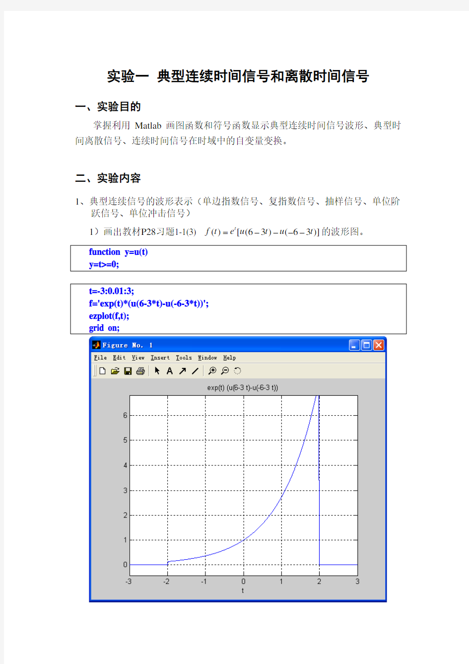
1)画出教材P28习题1-1(3) ()[(63)(63)]t f t e u t u t =----的波形图。 function y=u(t) y=t>=0;
t=-3:0.01:3;
f='exp(t)*(u(6-3*t)-u(-6-3*t))';
ezplot(f,t);
grid on;
2)画出复指数信号()()j t f t e σω+=当0.4, 8σω==(0 波形图。 t=0:0.01:10; f1='exp(0.4*t)*cos(8*t)'; f2='exp(0.4*t)*sin(8*t)'; figure(1) ezplot(f1,t); grid on; figure(2) ezplot(f2,t); grid on; t=-10:0.01:10; f='sin(t)/t'; ezplot(f,t); grid on; t=0:0.01:10; f='(sign(t-3)+1)/2'; ezplot(f,t); grid on; 5)单位冲击信号可看作是宽度为∆,幅度为1/∆的矩形脉冲,即t=t 1处的冲击信号为 11111 ()()0 t t t x t t t other δ∆⎧<<+∆⎪=-=∆⎨⎪⎩ 画出0.2∆=, t 1=1的单位冲击信号。 t=0:0.01:2; f='5*(u(t-1)-u(t-1.2))'; ezplot(f,t); grid on; axis([0 2 -1 6]); 2、典型离散信号的表示(单位样值序列、单位阶跃序列、实指数序列、正弦序 列、复指数序列) 编写函数产生下列序列: 1)单位脉冲序列,起点n0,终点n f,在n s处有一单位脉冲。 2)单位阶跃序列,起点n0,终点n f,在n s前序列值为0,在n s后序列值为1。 对于1)、2)小题,最后以参数n0= -10,n f=10,n s= -3为例,画出各自 波形。 、 n0=-10;nf=10;ns=-3;n=n0:nf; x1=[zeros(1,ns-n0),1,zeros(1,nf-ns)]; figure(1); stem(n,x1); title('单位脉冲序列'); x2=[zeros(1,ns-n0),1,ones(1,nf-ns)]; figure(2); stem(n,x2); title('单位阶跃序列'); 3)画出教材P21图1-26,即[][]n x n a u n =当a =1.2, 0.6, -1.5, -0.8的单边指数序列(-2≤n ≤5)。 n=-2:5; subplot(2,2,1) x1=1.2.^n.*u(n);stem(n,x1); title('1.2^n*u(n)'); subplot(2,2,2) x2=0.6.^n.*u(n);stem(n,x2); title('0.6^n*u(n)'); subplot(2,2,3) x3=(-1.5).^n.*u(n);stem(n,x3); title('(-1.5)^n*u(n)'); subplot(2,2,4) x4=(-0.8).^n.*u(n);stem(n,x4); title('(-0.8)^n*u(n)'); 4)画出教材P21图1-27,即00[]sin(), 7x n n π =ΩΩ=的正弦序列(-7≤n ≤14)。 n=-7:14; x=sin(pi/7*n); stem(n,x); title('x[n]=sin(\Omega_0n) 正弦序列'); 5)画出复指数序列/6[]j n x n e π=和3[]j n x n e =的实部和虚部(-50≤n ≤50)。 n=-50:50; figure(1) x1=cos(pi/6*n);stem(n,x1); title('cos(n\pi/6) 实部'); figure(2) x2=sin(pi/6*n);stem(n,x2); title('sin(n\pi/6) 虚部'); figure(3) x3=cos(3*n);stem(n,x3); title('cos(3*n) 实部'); figure(4) x4=sin(3*n);stem(n,x4); title('sin(3*n) 虚部'); 3、信号的自变量变换 1)编写程序(函数),画出教材P10图1-13(a)即f(t)的波形(-6 2)利用1)中建立的函数,通过自变量替换方式依次画出图1-13(b)、(c)、 (d)即f(t+5)、f(-t+5)、f(-2t+5)的波形(-6 syms t; f='u(t)-u(t-2)'+(1+t)*'u(t+1)-u(t)'; subplot(2,2,1);ezplot(f,[-2,3]); axis([-2 3 -0.2 1.2]);title('f(t)');grid on; f1=subs(f,t,t+5); subplot(2,2,2);ezplot(f1,[-7,-2]); axis([-7 -2 -0.2 1.2]);title('f(t+5)');grid on; f2=subs(f,t,-t+5); subplot(2,2,3);ezplot(f2,[2,7]); axis([2 7 -0.2 1.2]);title('f(-t+5)');grid on; f3=subs(f,t,-2*t+5); subplot(2,2,4);ezplot(f3,[-1,4]); axis([-1 4 -0.2 1.2]);title('f(-2t+5)');grid on;