PMSM控制方式FOC_MTPA_弱磁简介
- 格式:pptx
- 大小:873.17 KB
- 文档页数:16


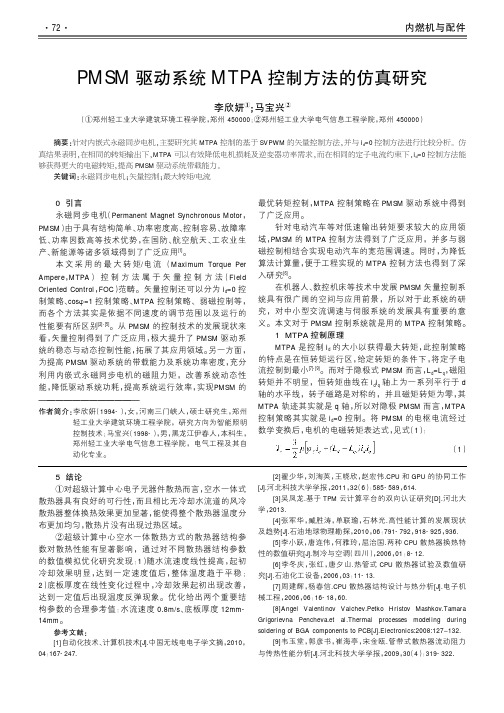
0引言永磁同步电机(Permanent Magnet Synchronous Motor,PMSM)由于具有结构简单、功率密度高、控制容易、故障率低、功率因数高等技术优势,在国防、航空航天、工农业生产、新能源等诸多领域得到了广泛应用[1]。
本文采用的最大转矩/电流(Maximum Torque Per Ampere,MTPA)控制方法属于矢量控制方法(Field Oriented Control,FOC)范畴。
矢量控制还可以分为i d=0控制策略、cosφ=1控制策略、MTPA控制策略、弱磁控制等,而各个方法其实是依据不同速度的调节范围以及运行的性能要有所区别[2]-[5]。
从PMSM的控制技术的发展现状来看,矢量控制得到了广泛应用,极大提升了PMSM驱动系统的稳态与动态控制性能,拓展了其应用领域。
另一方面,为提高PMSM驱动系统的带载能力及系统功率密度,充分利用内嵌式永磁同步电机的磁阻力矩,改善系统动态性能,降低驱动系统功耗,提高系统运行效率,实现PMSM的最优转矩控制,MTPA控制策略在PMSM驱动系统中得到了广泛应用。
针对电动汽车等对低速输出转矩要求较大的应用领域,PMSM的MTPA控制方法得到了广泛应用,并多与弱磁控制相结合实现电动汽车的宽范围调速。
同时,为降低算法计算量,便于工程实现的MTPA控制方法也得到了深入研究[6]。
在机器人、数控机床等技术中发展PMSM矢量控制系统具有很广阔的空间与应用前景,所以对于此系统的研究,对中小型交流调速与伺服系统的发展具有重要的意义。
本文对于PMSM控制系统就是用的MTPA控制策略。
1MTPA控制原理MTPA是控制i d的大小以获得最大转矩,此控制策略的特点是在恒转矩运行区,给定转矩的条件下,将定子电流控制到最小[7]-[9]。
而对于隐极式PMSM而言,L d=L q,磁阻转矩并不明显,恒转矩曲线在i d i q轴上为一系列平行于d 轴的水平线,转子磁路是对称的,并且磁矩转矩为零,其MTPA轨迹其实就是q轴,所以对隐极PMSM而言,MTPA 控制策略其实就是i d=0控制。

PMSM单电流调节器弱磁控制策略研究摘要在PMSM的数学模型基础上,研究了其基于单电流调节器的两种不同弱磁控制方法,即变交轴电压法和电压角度法,分析了其控制原理,可以看出两种控制方法都具有很好的鲁棒性;对其控制原理进行了比较,可知两种控制方法在直轴电压和交轴电压获取方式不同;分别采用以上两种方法对PMSM进行Matlab/Simulink建模与仿真。
结果表明,电压角度法具有更好的带载能力或升速能力,变交轴电压法具有更加平稳的转速波形且电流波形更佳。
关键词单电流调节器变交轴电压电压角度弱磁控制永磁同步电机0 引言随着稀土永磁材料的发展使得永磁同步电机(Permanent Magnet Synchronous Motor,简称PMSM)逐渐在一些方面取代了上述两种交流电机,永磁同步电机是用永磁体代替电励磁同步电机的转子,使其具有与异步电机相同的结构简单的优点,而同时又兼顾了电励磁同步电机功率因数高、效率高的优点,基于矢量控制的永磁同步电动机以其优良的控制性能、高功率密度和高效率,越来越多地用于各种高性能伺服系统及其它领域。
PMSM基速以下的矢量控制有cosφ=1控制、id=0控制、MTPA控制等,基速以上采用弱磁控制,为的是能够获得更宽的调速范围。
传统的弱磁控制方法中都有两个电流调节器,分别为id和iq调节器,在进行弱磁控制时,由于电机输入电压达到了极限值,随着电机转速的不断升高,使得控制电路中的直轴和交轴电流调节器饱和,相互之间耦合增强,结果导致电机的电流、转矩和转速难以较好地跟踪给定值,电机的动态性能逐渐变差,更有甚者,使整个系统失去稳定,为此,徐隆亚教授和Song Chi博士提出了一种新颖的弱磁控制策略,该策略中保留直轴电流调节器,而弃掉了与之对应的交轴电流调节器,所以称之为单电流调节器控制。
在PMSM单电流调节器控制的发展过程中,又出现了基于单电流调节器弱磁控制的多种控制方法,每一种控制方法都具有各自的优点,对其中的变交轴电压单电流调节器弱磁控制方法(SCR-VQVC)和电压角度单电流调节器弱磁控制方法(SCR-V AC)分别进行分析研究,得到各自的在PMSM弱磁控制中的优缺点,并运用Matlab/Simulink 对其进行了建模与仿真以验证分析结果。

本文档是针对PMSM 电机FOC 控制驱动请注意区别42永磁同步电机(PMSM )引线说明电机相线黄U绿V蓝W传感器接口1GND电源地2VCC电源正(5V)3PW+霍尔传感器W4PV-V5PU+U6PZ+编码器Z+7PB+B+8PA+A+9NC无信号10NC11NC12NC13PZ-编码器Z-14PB-B-15PA-A-传感器接口引脚顺序定义42永磁同步电机(PMSM)参数供电电压24 V额定功率63W额定力矩0.2 N.M峰值力矩0.6 N.M额定转速3000 RPM 额定电枢电流 3.13 A力矩系数0.057 N.M/A 反电势系数 4.13 V/KRPM 磁极8(4对极)编码器1000线相电阻0.89±10%Ω相电感0.62±20%mH电机驱动板与PMSM 电机接线说明序号驱动板接口功能说明电机引脚1U 电机接口直流无刷电机动力线注意这里实际是将蓝线(W)和黄线(U)对调蓝电机粗线2V 绿3W 黄4VCC 外部电源外部24V 电源供电,驱动板允许接入电源范围:18~36V 直流电源5GND15V 电压输出,可以为外部设备供电PMSM 电机传感器专用接口霍尔传感器接口电机动力线&电源注意:请使用带电压电流保护的24V 电源供电,一般设置电源为24V 2A 输出,空载时候,电机正常运转时总电流大概是200mAPMSM 电机不使用该端子接口,直接使用驱动板左上角VGA 接口的传感器接口注意:调试时候严禁直接使用锂电池供电,必须使用带保护的电源供电。
这里电机的U(黄)线实际接驱动板的W接口;电机的W(蓝)线实际接驱动板的U接口。
注意:1.调试时候需要把开发板上的跳线帽都去掉,防止信号干扰,无刷电机例程都不需要跳线帽的2.开发板需要单独外部供电,使用USB线或者外部电源供电,如下图:霍尔传感器模式FOC控制例程连线方法对应以下例程:YSF1_PMSM-005. FOC v4.2_HallSensor_42PMSM YSF1_PMSM-008. FOC v2.0_HallSensor_42PMSM无刷电机驱动板与YS-F1Pro开发板接线说明序号模块引脚功能说明开发板引脚2U霍尔传感器霍尔传感器接口PC84V PC7 6W PC6 8U线电流电机驱动臂电流采集PC110V PC2 12W PC3 13V_BUS外部电源电压检测(过压、欠压保护)PC5 14温度环境温度检测(高温保护)PC0 15PU_H梯形方波驱动信号正弦波(SVPWM)驱动信号PA816PU_L PB1317PV_H PA918PV_L PB1419PW_H PA1020PW_L PB1522SD ShutDown引脚,停机,高电平有效与GND连接或者悬空21GND电源线开发板和驱动板至少需要连接一根GND线。
基于MTPA的电动汽车用同步磁阻电机控制随着环保意识的不断增强和电动汽车的普及,同步磁阻电机逐渐成为电动汽车的主要驱动电机之一。
基于磁通定向控制(MTPA)的同步磁阻电机控制技术,可以实现对电动汽车驱动系统的精准控制,提高电动汽车的整体性能和能效。
一、同步磁阻电机技术介绍同步磁阻电机是一种利用磁场产生力矩来驱动电机旋转的电机。
它通过控制磁场的方向和强度,使电机按照一定规律进行旋转。
同步磁阻电机具有结构简单、效率高、功率密度大等优点,因此在电动汽车领域具有广阔的应用前景。
二、磁通定向控制(MTPA)技术原理磁通定向控制(MTPA)是一种用来控制同步磁阻电机的技术,通过改变电机磁通的方向和强度,使电机按照期望的轨迹进行旋转。
MTPA技术是一种高级的磁场控制技术,可以在不同负载条件下,实现最优的磁通定向,从而最大限度地提高电机的性能和效率。
三、基于MTPA的同步磁阻电机控制策略基于MTPA的同步磁阻电机控制策略,主要包括磁场定向控制、电流控制和速度控制。
通过对电机磁场的定向控制,可以实现最佳的磁通分布,从而最大限度地提高电机的输出功率和效率。
通过对电机电流和速度的控制,可以实现对电机的精准调节,使其在不同工况下都能够保持最佳的性能。
四、基于MTPA的同步磁阻电机控制系统基于MTPA的同步磁阻电机控制系统由控制器、传感器和执行器组成。
控制器通过对传感器采集的数据进行处理,生成相应的控制信号,并通过执行器对电机的磁场、电流和速度进行调节,实现对电机的精准控制。
控制器还可以通过通信接口与电动汽车的整车控制系统进行通信,实现对电机的整体协调控制。
六、基于MTPA的同步磁阻电机控制在电动汽车领域的应用基于MTPA的同步磁阻电机控制技术已经在众多电动汽车中得到应用,并取得了显著的效果。
通过采用MTPA技术,电动汽车可以实现更高的驱动效率和更好的动力性能,提高了整车的性能和能效。
基于MTPA的同步磁阻电机控制技术还可以有效地降低电动汽车的能源消耗和排放,符合现代社会对环保和可持续发展的要求。
基于FOC的PMSM速度控制系统的研究根据磁场定向控制理论以及永磁同步电动机调速控制系统的控制方案建立仿真模型,并对永磁同步电动机的调速过程进行仿真。
仿真结果较好地反映了永磁同步电动机的调速运行过程,对进一步开发永磁同步电动机速度控制系统具有重要意义。
l近年来,随着控制理论、永磁材料和电力电子技术的发展,基于磁场定向控制的永磁同步电动机(PMSM)以其优良的控制性能、高功率密度和高效率,广泛应用于各种高性能伺服系统及其他领域。
本文对永磁同步电动机的磁场定向控制(FOC)系统进行了理论研究与分析,并运用Matlab/Simulink对其调速系统进行建模与仿真。
2永磁同步伺服电动机的模型是一个多变量、非线性、强耦合系统。
为了实现动态过程的矢量控制,首先要实现解耦。
转子磁场定向控制是一种常用的解耦控制方法。
转子磁场定向控制实际上是将Odq同步旋转坐标系放在转子上,随转子同步旋转。
其d轴(直轴)与转子的磁场方向重台(定向),q轴(交轴)逆时针超前d轴90°电角度,如图1所示。
图l(图中转子的磁极对数为1)表示转子磁场定向后,定子三相不动坐标系A、B、c与转子同步旋转坐标系Odq的位置关系。
定子电流矢量is在Odq坐标系上的投影id、iq可以通过对iA、iB、iC的Clarke变换(3/2变换)和Park变换(交/直变换)求得,因此id、iq是直流量。
三相永磁同步伺服电动机的转矩方程为:式中,ψd、ψq——定子磁链在d、q轴的分量;ψf——转子磁钢在定子上的耦合磁链,它只在d轴上存在;p——转子的磁极对数;Ld、Lq——永磁同步电动机d、q轴的主电感。
式(1)说明转矩由两项组成,括号中的第一项是由三相旋转磁场和永磁磁场相互作用所产生的电磁转矩;第二项是由凸极效应引起的磁阻转矩。
对于嵌入式转子,Ld<Lq,电磁转矩和磁阻转矩同时存在。
可以灵活有效地利用这个磁阻转矩,通过调整和控制β角,用最小的电流幅值来获得最大的输出转矩。
Abstract —This paper presents a simplified fuzzy logic based speed control scheme of an interior permanent synchronous motor (IPMSM). The proposed FLC is designed based on conventional max torque per ampere below the rated speed and flux weakening control above the rated speed. The simplified fuzzy logic controller is suitable for real time implementation because of the less computational burden. The application MATLAB Simulink was used for simulations of the FLC based IPMSM drive. The efficacy of the proposed simplified fuzzy logic controller base drive of the IPMSM with flux weakening is verified by the simulation.I.I NTRODUCTIONIn the recent years the interior permanent magnet synchronous motor (IPMSM) has gained the increasing popularity for various industrial drive applications. IPMSM has a mechanically robust rotor construction, a rotor saliency, and the low effective air gap. These features permit control of the machine not only in constant torque region but also in constant power region up to a high speed by means of flux weakening [1-15].In most previous studies the performance of IPMSM drive system in the extended speed region was strongly dependent on the motor parameters because the model of IPMSM, especially stator voltage equation of the motor, is basically used for the flux weakening control [1]. And, the improper tuning of the parameters of IPMSM drive may result in reduced torque capability and stability problems, especially in flux weakening mode [5]. In fuzzy logic controller, the system control outputs are based on a human logic model. The FLC is more robust than the conventional controllers; it can handle many nonlinear systems. Thus, recently, the fuzzy logic controller is being used for motor control purpose. As compared to the conventional PID controllers, the FLC has no dependency on the parameters of the IPMSM [7].It is found that the proposed FLC is insensitive to temperature changes, parameters variations and load torque disturbances [14]. This simplified FLC could be a suitable replacement for the conventional PI controller for high performance drive systems.II.M ATHEMATICAL MODEL OF THE IPMSMThe mathematical model of an IPMSM drive can be described by the following equations in a synchronously rotating rotor d-q reference frame for assumed sinusoidal stator excitation as: qd s d q q q di u R i L L i dtω=+− (1) q q s q qd d f di u R i L L i dtωωψ=+++ (2)3()2em n f q d q d q T p i L L i i ψ⎡⎤=+−⎣⎦ (3) rem L r d T T B J dtΩ=+Ω+ (4) Where f ψis flux linkage due to permanent magnet excitation,d L and q L are d-q-axis inductance, d i and q i ared-q-axis current, respectively; d u and q u are d-q-axis stator voltage.n p is the number of poles pairs. It is also to be notedthat the torque (3) is nonlinear because of the reluctance torque [4].III.D ESIGN OF S IMPLIFIED FLC FOR IPMSMThe IPMSM speed control system need consider the voltage and the current limitation. The maximum voltage that the inverter can supply to the machine is limited by DC link voltage which defined as dc V ,also the maximum current lim i is determined by the inverter and the motor. Therefore thevoltage and the current of the motor have the following limits:d V ≤(5) limi ≤ (6)ωek k ωd dtFig.1. block diagram of the proposed control systemThe block diagram of the proposed FLC based IPMSM drive system is show in figure 1.The full operating range of the IPMSM can be divided into two regions: below the rated speed where the torque is maintained constant, above the ratedspeed where the power is maintained constant. As the speed ofthe motor is the only signal which contains the information of Simplified Fuzzy Logic Based Flux Weakening Speed Control of IPMSMDriveHuangyuan Wu, Shuanghong Wang ,Chenglin GuState Key Laboratory of Advanced Electromagnetic Engineering and TechnologyHuazhong University of Science and TechnologyWuhan Hubei P.R.China E-mail: whynot1006@the operating region. So the inputs of the controller should contain the speed error, the acceleration, the rotor speed. The output of the controller are selected as d and q axis current to control the torque and the flux. The main challenge of the controller is to design the membership functions between the inputs and the outputs [2].A. Design of FLC for Constant Torque RegionAs the IPMSM has a saliency, the reluctance is available. Thus, in order to increase the whole efficiency of the IPMSM drive system, the reluctance torque should be properly utilized. Below the rated speed, the maximum torque per ampere (MTPA) curve could be achieved by differentiating (3) and setting is to zero.2()3()02d q q em f d q d q d L L i dT P L L i di i ψ⎡⎤−=+−−=⎢⎥⎢⎥⎣⎦(7) 222q s di I i =− (8)From (7) and (8), the d-q-axis components of the currentvector for the MTPA are derived as:2()f d d q i L L ψ−=−− (9) with the load increase. At the rated load and speed conditions, it will touch the current limit circle. The real-time complication of the drive system becomes complex using the expression (9). The relationship between the d -q -axis currentcan be simplified using the Maclaurin series as: 3243()()d q d q d q q ffL L L L i i i ψψ−−=−−⋅⋅⋅Using the parameters that are given in the Appendix, it isfound that the ()1d q f L L ψ−<<. Although with the increase on the order of q i , the value of the corresponding term increases, the values are very low, thus, the sixth-order and higher order terms of q i can be neglected. Hence, the simplified equation can be written as:3243()()d q d q d q q ffL L L L i i i ψψ−−=−(10)As show in figure 2, the simplified equation curve is almost the same as the non-simplified one. Thus, in the real-timeimplementation, this simplified equation can be utilized as a basis function of d i below the rated speed. In the FLC design, the scaling factor for q i (iqk ) is selected by trial and error in such a way that the motor at rated condition, then the scaling factor for d i (id k ) will be as2422(())()iq iq d q f d q f k k L L L L ψψ+−− (11)Therefore, the current point at the steady status will be right on the MTPA curve with the required torque.Fig.2. MTPA control in constant torque regionB. Design of FLC for Constant Power RegionAbove the rated speed, the magnetic flux could be weakened by the armature reaction. Below the rated speed, the operatingpoint will move alone the trajectory of the MTPA, and above the rated speed, it will follow the voltage limit curve of the corresponding speed, as show in figure 3. Finally, it will reachthe intersection point of voltage curve with the required torque curve. The relationship between d-q-axis current in flux weakening region considering the voltage constrained is (12): f d di Lψ=− (12) In order to reduce the complication burden of the drive system, this equation could also be simplified. At first, the speed c ω is defined as:limc fu ωψ=Then, write the rotor speed as per unit calculation:pu cωωω=Like the constant torque region, using Maclaurin seriesexpansion and the d i expression is:22f f q q pu d q d d pu d f L L i i L L L ψψωωψ=−+−(13) As show in figure 3, the error between curves of equation (13) and equation (12) is very small. Therefore, the simplified equation (13) can be utilized as a basis function of d i abovethe rated speed.Fig.3. Flux weakening control in power constant regionC Design of FLC ruleIn this work, the fuzzy logic theory introduced by Zadeh[17]. Once the basis equation is chosen, the next step is to design the fuzzy rules of the controller. The membership functions between the inputs and outputs are shown in Fig.4. The rules used for the proposed FLC algorithm are as follows:1) If ωΔis positive high (PH), then q i is positive high (PH).2) If ωΔis positive middle (PM), then q i is positive middle (PM).3) If ωΔis positive small, then q i is positive small (PS).4) If ωΔis ZE (zero), then q i is not changed (NC). 5) If ωΔis negative high (NH), then q i is negative high (NH). 6) If ωΔis negative middle (NM), then q i is negative middle (NM).7) If ωΔis negative small (NS), then q i is positive small (NS).8) If ω is positive above rated (POR), then q i is positive small (PS).9) If ωis negative above rated (NOR), then q i isnegative small (NS).Δ ω(a) Member ship for ωΔω(b) Member ship for ωI s(c) Member ship for q i Fig.4. Member ship functionIV.S IMULATION R ESULTSThe performance of the simplified FLC based flux weakening speed control of IPMSM drive has been proved by the computer simulation and the experiments. The speed andcurrent responses are observed under difference operating conditions, such as, various command speeds, differentloading conditions in both operating regions. From theobtained results, it is obvious that the FLC based IPMSM drive has been found superior to the conventional PI-controllerbased system. time in secendsFig.6. Simulation speed response at load 2N-m with MTPAtime in secendsFig.7. simulation speed response at load 2N-m with FWtime in secendsc u r r e n t i n a m p e r eFig.8. experiment currents response at load 2N-m with MTPA1200r/mtime in secendsc u r r e n t i n a m p e r eFig.9.simulation currents response at load 2N-m with FW3600r/pV. C ONCLUSIONThis paper presents a simplified FLC based wide speedrange operation of IPMSM drive system. The control scheme utilized MTPA in the constant torque region and flux weakening in the constant power region where have been presented a simplified FLC and relatively simpler expressions of d-q-axis currents, thus it requires less computing capacity. The application MATLAB Simulink was used for simulations of the FLC based IPMSM drive; the parameters were the same as the appendix. The results indicate that the simplified FLC is robust and suitable for IPMSM drive applications.APPENDIXThe parameters of the motor used in simulation and experiment are d L =27mH, d L =67mH, number of poles=4, input DC voltage=300V, a rated current of 4A and permanent magnate flux linkage is 0.272Wb.VI.R EFERENCES[1] Morimoto S ,Takeda Y .Expansion of operating limits for permanentmagnet motor by current vector control considering inverter capacity [J].IEEE Transactions on Industry Applications ,1990,26(5):866-871. [2] Macminn SR ,Jahns T.M .Control techniques for improved high-speedperformance of interior [J].IEEE Transactions on Industry Applications ,1991,27(5):997-1004.[4] JTae-Suk Kwon ,Gi-Young, Choi .Novel Flux-Weakening Control of anIPMSM for Quasi-Six-Step Operation [J].IEEE Transactions on Industry Applications ,2008,44(6):1722-1731.[5] Morimoto S ,Sanada M..Wide-speed operation of interior permanent magnetsynchronous motors with high-performance current regulator [J].IEEE Transactions on Industry Applications ,1994,30(4):920-926. [6] Jung-Woo Park ,Dae-Hyun Koo .Improvement of control characteristics ofinterior permanent-magnet synchronous motor for electric vehicle [J].IEEE Transactions on Industry Applications ,2001,36(6):1754-1760. [7] Uddin, M. N.,Rahman, M. A .Fuzzy logic based speed control of an IPMsynchronous motor drive [J].IEEE Transactions on Industry Applications ,1999,3(3):1259-1264.[8] Soong, W L ,Ertugrul, N .Field-weakening performance of interiorpermanent-magnet motors [J].IEEE Transactions on Industry Applications ,2002,38(5):1251-1258.[9] Uddin, M. N.,Radwan, T. S ,Rahman, M. A .Performance of interiorpermanent magnet motor drive over wide speed range [J].IEEE Transactions on Energy Conversion ,2002,17(1):79-84.[10] Cerruto E ,Consoli A ,Raciti, A ,Fuzzy adaptive vector control ofinduction motor drives [J]. IEEE Transactions on Industry Applications ,1997,12(6):1028-1040.[11] S Bolognani , M. Zigliotto .Hardware and software effectiveconfigurations for multi-input fuzzy logic controllers [J].IEEE Transactionon Fuzzy Systems ,1998,12(6): 173-179.[12] Butt C B , Hoque M A ,Rahman M A..Simplified fuzzy-logic-basedMTPA speed control of IPMSM drive [J].IEEE Transaction on Industry Applications ,2004,40(6): 1529-1533.[13] M Nasir Uddin , M Azizur Rahman .High-Speed Control of IPMSMDrives Using Improved Fuzzy Logic Algorithms [J].IEEE Transaction on Industrial Electronics ,2007,54(1): 190-199.[14] Uddin M N., Chy, M. M. I..A Novel Fuzzy-Logic-Controller-BasedTorque and Flux Controls of IPM Synchronous Motor [J].IEEE Transaction on Industrial Electronics ,2010,46(3): 1220-1229.[15] Hossain, M. S., Hossain, M. J..Performance analysis of a novel fuzzylogic and MTPA based speed control for IPMSM drive with variable d- and q-axis inductances [J].Computers and Information Technology .2009: 361-366.[16] Rahman, M. A , Milasi, R. M ,Lucas, C .Implementation of EmotionalController for Interior Permanent-Magnet Synchronous Motor Drive [J].IEEE Transactions on Industry Applications ,2008,44(5): 1466-1476. [17] Tursini, M ,Chiricozzi, E.,Petrella R .Feedforward Flux-WeakeningControl of Surface-Mounted Permanent-Magnet Synchronous Motors Accounting for Resistive Voltage Drop [J].IEEE Transactions on Industry Applications ,2008,57(1): 440-448.[18] Cheol, Jo ,Ji-Yun, Seol ,In-Joong, Ha .Flux-Weakening Control of IPMMotors With Significant Effect of Magnetic Saturation and StatorResistance[J].IEEE Transactions on Industrial Electronics ,2008,55(3): 1330-1340.[19] Dutta R ,Rahman M. F .A Comparative Analysis of Two Test Methods ofMeasuring dq -Axes Inductances of Interior Permanent Magnet Machine [J].IEEE Transactions on Magnetics ,2006,42(11): 3712-3718.。