8 6000系列设备初始化
- 格式:ppt
- 大小:1.92 MB
- 文档页数:37
准备工作
1. 具备串口的终端电脑(USB to serial).
2. 使用标记为“180-055”灰色适配器(3par自带).
3. 标准RJ45网线(使用自带蓝色线).
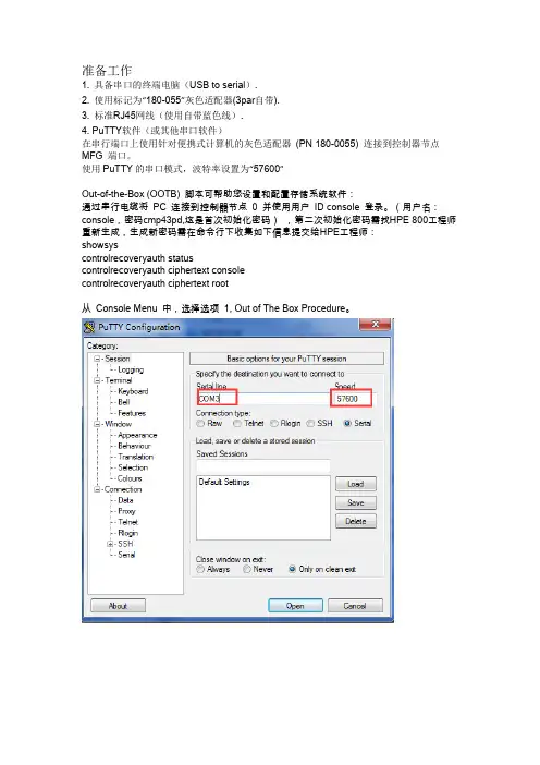
4. PuTTY软件(或其他串口软件)
在串行端口上使用针对便携式计算机的灰色适配器(PN 180-0055) 连接到控制器节点MFG 端口。
使用PuTTY的串口模式,波特率设置为“57600”
Out-of-the-Box (OOTB) 脚本可帮助您设置和配置存储系统软件:
通过串行电缆将PC 连接到控制器节点0 并使用用户ID console 登录。
(用户名:console,密码cmp43pd,这是首次初始化密码),第二次初始化密码需找HPE 800工程师重新生成,生成新密码需在命令行下收集如下信息提交给HPE工程师:
showsys
controlrecoveryauth status
controlrecoveryauth ciphertext console
controlrecoveryauth ciphertext root
从Console Menu 中,选择选项1, Out of The Box Procedure。
如第二次初始化:选8.Perform a deinstallation(重新执行安装),自动重启后再执行1;
Totp:时间戳console密码,失效时间一般是半小时到一小时Cipher:密文方式,console密码不过期。

FANUCS 系列数字式主轴驱动器的参数初始化与设定在数字式主轴驱动器的维修过程中,有时会出现由于偶然性干扰或误操作引起驱动器内部参数的混乱或丢失,在这种情况下,需要进行参数的重新设定与参数的初始化操作进行恢复。
此外,在驱动器出现“A”、“AL~17”等有关CPU、ROM 的原因不明的偶发性报警时,通过参数的初始化操作,往往可以排除故障,恢复驱动器的正常工作。
A06B-6059 系列数字式主轴驱动器参数的初始化操作与参数设定的方法如下:(1)参数的初始化操作FANUCA06B-6059 系列数字式主轴驱动器参数的初始化操作按以下步骤进行:1)切断驱动器电源,将设定端S1 置TEST(在1S~3S 软件版本13B 前将SH 置SET)。
2)接通驱动器电源。
3)同时按住MODE、UP、DOWN、DA TASET4 个键,并保持1s 以上。
4)当显示器由全暗变为“FFFFF”后,松开全部键。
5)同时按住MODE、UP 键,使参数显示FC-22。
6)按住DA TASET 键 1 秒以上,显示器显示“GOOD”,标准参数写入完成。
7)切断驱动器电源,将S1(SH)重新置“DRIVE”。
8)如需要,在接通电源后再进行其他参数的调整和设定。
通过以上操作,可以使参数F41~F53 恢复到出厂设定值,同时清除有关CPUROM 的原因不明的偶发性故障。
(2)参数的显示与写入操作当驱动器参数需要检查或调整时,可以按照以下步骤进行:1)接通驱动器电源。
2)时按住MODE、UP、DOWN、DA TASET 四个键,并保持1s 以上。
3)当显示器由全暗变为“FFFFF”后,松开全部键。
4)同时按住MODE、UP 键,参数号增加:同时按住MODE、DOWN 键,参数号减少。
5)松开MODE、UP(DOWN)键后,显示参数值。
6)在松开MODE 键10s 后,显示回到转速显示方式。
参数的修改步骤如下:1)按以上第1~5 步骤选择需要修改的参数显示。

P/N: 1802086000011 *1802086000011*ioPAC 8600 Series Quick Installation GuideVersion 1.1, October 2020Technical Support Contact Information/supportMoxa Americas:Toll-free: 1-888-669-2872 Tel: 1-714-528-6777 Fax: 1-714-528-6778 Moxa China (Shanghai office): Toll-free: 800-820-5036 Tel: +86-21-5258-9955 Fax: +86-21-5258-5505 Moxa Europe:Tel: +49-89-3 70 03 99-0 Fax: +49-89-3 70 03 99-99 Moxa Asia-Pacific:Tel: +886-2-8919-1230 Fax: +886-2-8919-1231 Moxa India:Tel: +91-80-4172-9088 Fax: +91-80-4132-10452020 Moxa Inc. All rights reserved.IntroductionThe ioPAC 8600 modular programmable controller supports CPU, power, backplane, and I/O modules, giving users greater flexibility for selecting the best module for different applications. The controllers have 5, 9, or 12 I/O slots and support both 85M series and 86M series modules. The ioPAC 8600 supports C/C++ and IEC 61131-3 programming capability,rail-level surge and ESD protection, a -40 to 75°C operating temperature range, anti-vibration, hot-swappability of modules, as well as two 10/100 Mbps Ethernet ports with two MACs (Port Trunking ready) or Ethernet bypass function with one MAC. With Moxa’s MX-AOPC UA Suite, the ioPAC 8600 series provides a comprehensive solution for data acquisition and control applications in harsh environments.Package Checklist• 1 x ioPAC 8600 CPU module• 1 x console cable• 1 x quick installation guide (printed)AppearanceioPAC 8600 CPU ModuleioPAC 8600 Power ModuleInstallationWall-mounting KitSTEP 1: Use screws to attach the wall-mounting kit to the back of the ioPAC 8600, as shown below:STEP 2: Use screws to fix the wall mounting kit to a wall.Module Installation (Power-Off)The module’s PCB should align with the edge of theframe. Push the module into the slot and make surethe module is plugged into the backplane. Fasten thetwo screws using 3.5±0.5 kgf-cm of torque.Module Installation (Power-On)The module’s PCB should align with the edge of the frame. Push the module into the slot and make sure the module is plugged in to the backplane. Fasten the two screws using 3.5±0.5 kgf-cm of torque. It could take about ten seconds for the system to recognize and activate the module, at which point the module’s LED will turn green.Connecting the PowerA 24 to 110 VDC input power is applied to the positive(V1+ and V2+) and negative (V1- and V2-) terminals onthe connector.SD Card Installation1.Remove the screw holding the microSD card cover in place.2.Insert the microSD card into the microSD card slot.e the holding screw to fasten the cover in place.LED IndicatorsCategory Label Usage DescriptionSystem PWR CPU PowerOn: Power OnOff: Power OffRDYSystem Ready(Kernel)Green: System ReadyGreen Blinking: SystemBooting-upRed: System Error/ExecutingFactory DefaultRed Blinking: TriggeringFactory DefaultFirmwareUpgrade Mode(rotary switchmode 9)Green: Firmware UpgradeSuccessGreen Blinking: UpgradingFirmwareRed Blinking: FirmwareUpgrade ErrorC/C++ Version LED1,LED2User-defined User-definedIEC Version R/S Run/Stop ModeGreen: The CPU is runningOff: The CPU is idleERR ErrorRed: System, I/O, or ServiceErrorOff: No ErrorCommunication LAN1,LAN2EthernetCommunicationGreen: 100 MbpsAmber: 10 MbpsBlinking: Transmitting DataOff: DisconnectedRotary SwitchRotary Switch Position Mode ofOperation DescriptionIEC Version: 0 RUN mode RUN mode is the default operation mode. Use this mode for most tasks and configurations. The CPU will run automatically in this mode (this function should be enabled in RTUxpress).IEC Version: 1 STOP mode Stop the CPU (this function should be enabled in RTUxpress).C/C++ Version: 0 to 4IEC Version: 2 to 8ReservedRotary Switch Position Mode ofOperation DescriptionC/C++ Version: 5 to 8 User-defined9 Firmwareupgrade mode(only availablewhen booting up)Use this mode to update thefirmware from the SD card.1. Save the firmware file inthe root folder of the microSDcard. The filename must bertu.hfm.Note: For detailedinformation, see the sectionUpgrading the Firmwarefrom the SD Card in theioPAC 8600 SW User'sManual.2. Stop the ioPAC and insertthe SD card.3. Turn the rotary switch toposition 9 and then power upthe ioPAC.4. When the upgrade iscomplete, turn the rotaryswitch to 0 and reboot theioPAC.Note: The microSD cardshould be FAT32 format.Connecting to the ioPAC 8600 Series Controller Use the following configuration information to log in to the ioThinx 4530 Series controller:Port Default IP Subnet MaskLAN1 192.168.127.254 255.255.255.0LAN2 192.168.126.254 255.255.255.0 •Username: moxa•Password: moxaNOTE Be sure to configure the host PC’s IP address to use the same subnet as the unit. For example, 192.168.127.253 for LAN1 port. Ethernet ConnectionRJ45 Pin AssignmentContact Media Direct Interface Signal1 Tx+ (transmit)2 Tx- (transmit)3 Rx+ (receive)4 Not used5 Not used6 Rx- (receive)7 Not used8 Not usedM12 Pin AssignmentPin Connection 1 Tx+ 2 Rx+ 3 Tx- 4Rx-Serial ConnectionRemove the SD card cover and attach the 4-pin console cable to the console port.Serial Console Port Pin AssignmentPin Definition1 TxD2 RxD3 NC 4GNDSerial Console Settings Parameter ValueBaudrate 115200 bps Parity None Data bits 8 Stop bits 1 Flow Control None TerminalVT100Loading the Factory Default Settings1. Turn the rotary switch to position 0.2. When the system is booting up and the RDY LED is blinking GREEN,hold the reset button.3. Continue to hold the reset button until the “RDY” LED turns a solidRED, and then release the reset button. It will take around 90 seconds to complete the factory reset process.4. When the “RDY” LED starts blinking GREEN (indicating that the kernelis rebooting), the factory reset is completed.How to Download the SoftwareRelated software packages can be downloaded from the Moxa website. Step 1: Go to the following address:https:///en/supportStep 2: Select a product list from the drop-down box or type the model name in the search box. In the following screenshot, the ioLogik E1200 Series is used to illustrate.Step 3: Go to the Software & Documentation page to download the latest software for the product.SpecificationsInput Current 223 mA @ 24 VDCInput Voltage 24 to 110 VDCOperating Temperature -40 to 75°C (-40 to 167°F)Storage Temperature -40 to 85°C (-40 to 185°F)Moxa Inc.Fl.4, No. 135, Lane 235, Baoqiao Rd.Xindian Dist., New Taipei City, Taiwan R.O.C.。