
BMIE_DSP_Chap10_20151210
- 格式:pdf
- 大小:2.08 MB
- 文档页数:113

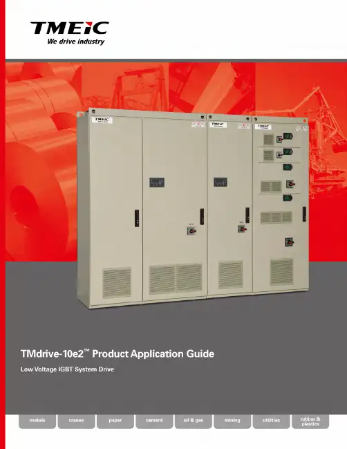
TMdrive-10e2 is anevolution in the familyof TMdrive® ac systemdrives offering:• High reliability• S imple configurationand maintenance• L ow cost of ownership• Compact designFeatures BenefitsState-of-the-art microprocessors including floating point calculation.Higher processing speed and communications for next generation control system.Per unit calculations are easy to understand.H eat pipe cooling technology.The IGBT power bridges use heat pipe cooling technology.R educes footprint and lowers audible noise. This technology saves valuable floor space and lowers the required cooling-air flow, reducing the associated audible noise.M icrosoft® Windows®-based configuration.The TMdrive-Navigator is used to configure, install, and maintain the TMdrive-10e2 drives.World-class tool across all system drives.Flexible tool connectivity.Native Ethernet drive interface allows flexible point-to-point TMdrive-Navigator communication over control LAN or even via your factory LAN.LAN options:• TC-net I/O™• Profibus-DP™• DeviceNet™• Modbus RTU• Ethernet Global Data (EGD)• ControlNet™Multiple controller platforms supported.For virtually all controller platforms, these LAN options provide seamless integration with the rest of your factory.Connectivity to legacy equipment.Existing equipment can be seamlessly integrated into new systems.Safety features according to:• ISO 13849 (Category 3)• IEC 61800-5-2 (Safety Integration Level 2)Risk is defined and analysis simplified according to these standards.Integrated hardware removes the requirement for external components to meet standards.The system is simplified and reliability improved.23Coordinated drive systems are an integral part of manufacturing processes in the metals industry. TMdrive-10e2 system drives address all of these applications by providing:• High reliability, low maintenance, compact design • L ow voltage application from a few to hundreds of drives • H igh-speed communication featuring robust control and diagnostics • Strip transport or Auxiliary applications • Continuous or batch operationsIn the pulp and paper industry, uninterrupted operation is priority one. The robust design of the TMdrive–10e2 heat pipe-cooled power bridges provides superior reliability and maintainability forpaper mill applications.In the automation of container cranes, tight integration between the system drive and the controller is a requirement. TMdrive-10e2’s compact and efficient design together with a multitude of LAN options enhance yard and dock side crane productivity. The high-performance networks provide:• High-speed real-time control • Full automation with no operator • R emote connectivity for configurationand monitoring4T wo-Level Phase Leg AssemblyThe cabinet style inverters have modular two-level phase leg assemblies.Each phase leg includes:• Heat pipe assembly1200 Frame Inverterperforms several functions:• S peed and torque regulation• Sequencing• I/O mapping• Diagnostic data gatheringA mounting bracket isprovided for an optionalLAN interface board.All TMdrive–10e2 productsinclude standard I/O, whichsupports an encoder, 24V dcand analog I/O. In addition,a resolver interface optioncan be provided. All I/O’s areterminated to a two-piecemodular terminal block foreasy maintenance. Eitherscrew or spring terminalblocks can be provided.Cabinet style inverters include bus tabs for easy motorbe supplied.Motor Connections andOptional Output ContactorHeat Pipe Cooling T echnologyThe cabinet style inverters and regenerative convertersuse heat pipes to cool the IGBT power switches andcapacitors. This technology reduces the footprint of5400 Frame Inverter Frame 15-100Frame 150Frame 250Draw-Out Style Inverters optional dc bus disconnect to allow lockout of individual inverters. The draw-out style inverters are tied to the dc bus using a set of staggered stab connectors that provide proper charging.draw-out style inverters are available in a very compact package. Draw-out inverters are mounted on heavy-duty slides with staggered connectors on the back that connect with the bus when slid into the cabinet. Motor cables are terminated at a common terminal block in the bottom of the cabinet. I/O and incoming ac power are mounted on modular terminal blocks for ease of maintenance.DC BusThe converter in each lineup (not shown here) generates dc power for each of the inverters. The inverters then create variable frequency ac power to control the induction motors. This dc power for the lineup is conveyed on a solid tin-plated copper bus near the bottom of the cabinets.Reliable low voltage ac system drive technology designed to reduce cost of ownership:• H eat pipe cooling technology that reducesthe size of the power bridge andaudible noise generated by thecooling fans• D raw-out style inverters for lowhp applications• A dvanced IGBTsincrease efficiency6TC-NET I/O • 8 words in/out Ethernet Global Data (EGD) • 10 words in/out Profibus-DP • 10 words in/out Modbus RTU • 10 words in/out ControlNet • 10 words in/out DeviceNet • 4 words in, 10 words out Certain other legacy LANs can also be supported on request.Safety features according to IEC 618005-2 (Safety Integration Level 2) and ISO 13849 (Category 3). Safety integrity level 2/category 3 is insured by independent gate command lockout via two hardware inputs; UVS1 and UVS2. In addition, when the optional output contactor is supplied it is also disabled by the UVS1 signal providingDigital Inputs Digital Inputs Digital Inputs • Quantity 4 user defined • Open Collector • Non-Isolated • Adds Quantity 5 user defined • Isolated or Non-isolated • Relay (1 A) or solid state (70 mA)• Adds Quantity 6 user defined • Isolated or Non-isolated • Relay (1A) or solid state (70mA)• Quantity 2 for UVS (SIL 2)• Quantity 4 configurable mapping • Non-Isolated • Adds Quantity 5 configurable • Isolated or Non-isolated • Relay or solid state• Adds Quantity 6 configurable • Isolated or Non-isolated • Relay or solid state • Quantity 1 configurable • Non-Isolated • 13-bit resolution • A dds Isolation to standard analog input • A dds Isolation to standard analog input • A dds additional 1 isolated channel, user defined • Quantity 1 user defined • Non-Isolated • 8-bit resolution• A dds Isolation to standard analog output • A dds additional 1 isolated channel, 8-bit, user defined• A dds Isolation to standard analog output • A dds additional 2 isolated channels, 8-bit, user defined • Excitation frequency of 1 or 4 kHz • S ource for resolvers is Tamagawa: www.tamagawa-seiki.co.jp• A quad B with marker • Maximum frequency of 100 kHz • D ifferential or single-ended 5 or 15 V dc• A quad B with marker • Maximum frequency of 100 kHz • H igh-resolution torque motor temperature feedback • 1 k Ω positive temperature coefficient RTD or other sensor requires selecting Option Unit Digital Outputs Digital Outputs Digital Outputs Analog Inputs Analog InputsAnalog Inputs Analog Outputs Analog Outputs Analog Outputs (Optional)Speed Feedback Resolver Input Speed Feedback Encoder Input Speed Tach Follower Output MotorTemperature Feedback 25 mA B Z+/- 10 V dc 1 mA 10 V 10 V +/- 10 V dc 4-20 mA 10 V 4-20 mA 10 V 4-20 mA 24 V dc 50 mA 24 V dc 24 V dc +24 V dc 10 mA +24 V dc 10 mA +24 V dc 10 mA TMdrive-10e2 features a flexible I/O system allowing a variety of I/O to connect directly to each inverter. Standard I/O shown below is always supplied. Additionally, either option unit A or B may be specified to extend I/O capability.UVS1Cubicle Panel (600 mm)Cubicle Panel (800 mm)Draw-out Panel (Option A)Draw-out Panel (Option B)7Optional analog meters can be supplied in addition to either the standard or enhanced display. Standard inverter I/O includes meter driver outputs that are +/- 10 V with 10-bit resolution. For cabinet style equipment, four meters are provided. For draw-out style, two meters are provided for each inverter.Optional Enhanced Keypad Standard Display RJ-45 Ethernet port is used for local tool connectionLEDs give a quick indication of the status of the unit.LED Indication DC Bus On when the DC Bus Discharged is dischargedReadyO n when the unit is ready to run Running O n when the unit is runningAlarm/Fault B linking LED indicates alarm condition, while solid LED indicates a faultInterlock button disables the driveDraw-out Enclosure DisplayThe TMdrive-10e2 has a wide array of control functions to suit any application:Analog input conditioning:• O ffset for each • G ain for each• R ollover protectionSimulation mode for testing and training:• Motor simulator • Load simulatorHigh-speed data capture buffer:• Configurable trigger data capture (8 channels)• Fault data capture (64 channels) • 14 kb bufferProtection:• Over speed • Speed error• Over frequency • Timed overcurrent• Cooling fan failure • Motor overheat• StallHigh-resolution motor temperature feedback:• T orque accuracy • Motor protectionOuter regulator with 4 modes:• S peed • T orque• S peed with droop • S aturated speedwith torque controlCurrent limits:• d i/dt • I nverting• S peed dependentAutomatic field adjustments:• Field weakening• Saturation compensationFour forms of load compensation:• I nertia • F riction• W indage • I mpactConfigurable sequential functions:• Start • Alarm• Stop • Trip, etc.T orque calculator:• A ccurately computes torquedelivered to the loadReference model:• M odel following control to eliminatemechanical resonance problemsInner regulator with 3 modes:• V ector with speed feedback• S ensorless vector• Sensorless scaler (Volts/Hz)it up through the chillDiagnostic and Protective Functions8The TMdrive-Navigator tool helps youmaintain TMEIC drives yourself.Engineers and technicians areempowered to understand how the driveworks and what the drive is doing. Anyuser can easily access current driveexpertise and know-how.Desktop-like search technology links topicalsignal lists, block diagrams, help files, productdocumentation, change history, and user notes.Windows techniques facilitate navigation within adrive and across the system. The status of all drivesis always in view.High speed data is automatically captured and savedin the event of a drive fault. Users can also capturehigh speed data based on their own trigger conditionsor perform high resolution real-time trending.Fault data can be automatically “pushed” to key users.The client-server architecture allows access to highperformance data from remote locations – with thesame resolution as if you were in the plant.Wizards support tuning of drive functions.Live block diagrams provide a real-time graphicalview of drive functions. Functions can be configureddirectly from the graphical view.Product documentation is integrated right into thetool. Users can even capture their own notes tobenefit future troubleshooting.Compatible with:• Windows XP, Vista, 7• Windows Server 2003, 200810TMdrive-10e2 Inverter EnclosuresOutput ContactorBus Fuse Optional DC Disconnect D C B u s Fig. 5Fig. 611Canada United States95%, motor power factor of 0.85, ambient temperature 0-40˚C (32-104˚F), and altitude below 1000 m (3280 ft) above sea level. Use actual motor data for final inverter selection.4. T he specified current ratings are continuous to which the referenced overload can be applied for a maximum of 60 seconds. Refer to application example on page 14.5. I nverters support bottom cable entry. Top cable entry is supported with one 600 mm (24 in) auxiliary cabinet between every two inverter cabinets.6. Each of the inverters requires 3-phase control power.7. F or high-performance torque regulation, a temperature sensor is mounted in the motor.for all cabinets.10. T he dc bus for the lineup has a maximum current capacity of 2350 amps.11. H igh temperature current derating: all frames -2.5% per ˚C above 40˚C.12. I nverter doors are electrically interlocked with controls to inhibit gating when the doors are open.13. L ow temperature current derating: frames 400 to 2400 -2% per ˚C below 0 ˚C. All other frames no derating.voltages up to 460 V, including 230 V, 380 V, 415 V, 440 V and 460 V690 V design supports motor voltages up to 690 V, including 575 V and 690 VOutput Frequency 0-300 Hz Continuous operation below 0.4 Hz requires derateOutput Chopping 1 kHz for all frames Frequency Up to 3 kHz available with deratingInverter Type Two-level voltage converter Modulation Pulse Width Modulation (PWM)Power Semiconductor Insulated Gate Bipolar Technology Transistor (IGBT)Operating 0 to 40°C (32 to 104°F) at rated load Temperature-20 to 50°C (-4 to 122°F) with derating Storage -25 to 55°C (-13 to 131°F) TemperatureHumidity 5 to 95% relative humidityNon-condensing Altitude 0 to 5000 m (16400 ft) above sea level Derate current ratings: 1% per 200 m (656 ft) altitude above 1000 m (3280 ft) Derate voltage 2.25% per 200 m (656 ft) for 460 V inverters above 4000 m (13120 ft)for 690 V inverters above 2000 m (6560 ft)Vibration 10-50 Hz, <4.9 m/s 2 (0.5 G)Enclosure IP20 (NEMA 1) IP32 or IP31 optional Cable Entrance Bottom is standard Top with optional auxiliary cabinet Wire Colors Per CSA/UL and CE Short Circuit Ratings 100 kA for ac and dc buswork 10 kA for control power Acoustic Noise ≤ 68 dB Mean Time to Repair 30 minutes to replace power bridge phase-leg MTBF > 41,000 hours Code Conformance Applicable IEC, JIS, JEM, UL, CSA and NEMA standards Cabinet Lockout (control power)95%With Speed Sensor (Resolver or Encoder)• Speed regulator accuracy: +/- 0.01%• Maximum speed response: 60 rad/sec • Torque linearity: +/- 3% with temperature sensor +/- 10% without temperature sensor • Maximum Torque current response: 1000 rad/sec • Torque range: 0-400% of rated motor torque • Maximum flux control range: 20%-100%Without Speed Sensor • Speed regulator accuracy: +/- 0.1% with temperature sensor +/- 0.2% without temperature sensor (Using 1% slip motor at rated flux)• Maximum speed regulator response: 20 rad/sec • Minimum continuous speed: 3%• Torque linearity: +/-10%• Maximum Torque current response: 1000 rad/sec • Torque range: 0-150% of rated motor torque Single DC disconnect Inverter LockoutResponse= 3/T (radians/s)12460Note: When two values exist, IEC/JEM value precedes UL value.1 – Twin Contactor* – Refer to Page 1013690V Design14When specifying an inverter, start from the process requirements and work through the motor to the inverter. The following example illustrates this process.The motor delivers constant torque from zero to base speed of 900 rpm and 150 kW (201 hp).Duty cycle requires 150% for 10 sec, but has a rms duty cycle of 150 kW (201 hp). S elect motor based on process requirements and compute required inverter kVA.• 150 kW (201 hp)• 900 rpm, 460 V • Efficiency = 0.954• Power factor = 0.765• Service factor = 1.15Select inverter based on continuous current and Scan the 150% entries in the inverter tables for a frame where the continuous current rating exceeds 297 amps. The 400 frame meets this criterion (455 amps ) and is appropriate for this application.I ac Converter = kW Shaft x 1000 x SF Mtr Eff Mtr x PF Mtr x 3 x V Motor rated voltage = 150 x 1000 x 1.150.954 x 0.765 x 3 x 460 V=297 amps Scan the specifications in the non-regenerative converter frame where the continuous current rating exceeds 245 pute the continuous dc current requirement of the converter based I dc Converter = kW Shaft x 1000 Eff Mtr x Eff Inv x V dc Bus = 150 kW x 10000.954 x 0.985 x 652= 245 ampsCompute the operating voltage of the dc bus. It is assumed that the specified in the application example above.Assumptions:• Converter at 100% of current rating • Transformer sized for converter • 5% high transformer tap is used Vdc Bus = 1.35 x V Converter line-to-line= 1.35 x 460 x 1.05= 652 V When specifying a converter, start from the process requirements and work through the motor to the inverter, and then the associated converter. The following example illustrates this process (continuation of inverter application example on top of page).When specifying a converter, start from the process requirements and work through the motor to the inverter, and then the associated converter. The following example illustrates this process (continuation of inverter application example above):Compute continuous ac current requirement of the converter based Scan the 150% for 60 sec entries in the regenerative the continuous current rating exceeds 203 amps. = kW dc x 1000 3 x V Converter line-to-line voltage = 162 kW x 1000 3 x 460 V = 203 amps Compute kW requirements into the inverter. It is assumed inverter specified in the application example above. It is also assumed that the converter is controlled to unity power factor.kWdc = kW ShaftEff Mtr x Eff Inv x Eff Conv= 150 kW0.954 x .985 x .985 = 162 kW Note: For sizing systems with peak powers in regenerative mode, a different equation is used to compute power requirements.kW dc = kW Shaft x (Eff Mtr x Eff Inverter x Eff Conv )I ac Converter C ompute continuous for the inverter based on the selected motor.15Input Frequency50/60 Hz ±20%TMdrive-P10e2 Input Chopping 2 kHz 180-242 V ac, 60 Hz 3-phase Displacement Power TMdrive-P10e2 - Unity power factor Factor (at all loads)。
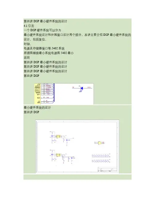
第四讲DSP 最小硬件系统的设计4.1引言一个DSP 硬件系统可以分为最小硬件系统设计和外围接口设计两个部分。
本讲主要介绍DSP 最小硬件系统的设计,包括复位、时钟、电源及存储器接口等.5402系统原理图继续最小系统电源图5402最小返回第四讲DSP 最小硬件系统的设计第四讲DSP 最小硬件系统的设计第四讲DSP 最小硬件系统的设计第四讲DSP最小硬件系统的设计第四讲DSP最小硬件系统的设计第四讲DSP最小硬件系统的设计第四讲DSP 最小硬件系统的设计返回4.2DSP系统的基本硬件设计4.2.1 复位电路电压公式:提问:输入方式比较,阻容颠倒可以不?电源刚加上电时,TMS320 DSP 芯片处于复位状态,/RS低使芯片复位为使芯片初始化正确,一般应保证/RS为低至少持续3 个CLKOUT 周期但是,在上电后,系统的晶体振荡器一般需要儿百毫秒的稳定期,一般为100~200ms。
选择R = 100K , C = 47μ,可得t1= 167ms 。
●此种复位特点:简单存在不足:有时不能可靠复位4.2DSP系统的基本硬件设计4.2DSP系统的基本硬件设计4.2.2 时钟电路4.2DSP系统的基本硬件设计4.2.2 时钟电路TMS320VC5402内部具有一个可编程锁相环(PLL),它可以配置为两种模式:( 1 ) PLL 模式。
输入时钟乘以一个1~31之间的常数;( 2 ) DIV 模式。
输入时钟除以2 或4 。
软件可编程PLL 受一个存储器映射(地址为58h )的时钟模式寄存器CLKMD 控制,CLKMD 用于定义PLL 时钟模块的配置。
复位后CLKMD的值根据DSP 芯片三根输入引脚CLKMD1~CLKMD3 确定,从而确定DSP 的工作时钟。
4.2DSP系统的基本硬件设计4.2.2 时钟电路由于DSP 的程序需要从外部低速EPROM 、EEPROM中调入,可以采用较低工作频率的DSP 复位时钟模式,待RAM CLKMD 的值,使芯片工作在较高的频率上。
北京邮电大学DSP硬件实验报告学院: 电子工程学院专业:姓名:学号:班级:实验一常用指令实验一、实验目的熟悉DSP开发系统的连接了解DSP开发系统的组成和结构和应用系统构成熟悉常用C54X系列指令的用法(程序寻址,寄存器,I/O口,定时器,中断控制)。
二、实验步骤与内容(一)简单指令程序运行实验源程序:;File Name:exp01.asm;the program is compiled at no autoinitialization mode --程序在非自动初始化模式下编译.mmregs --(enter memory-mapped registers into the symbol table) --进入记忆映射注册进入符号表.global _main --(identify one or more global(external)symbols)--定义一个或多个全局变量_main:stm(累加器的低端存放到存储器映射寄存器中) #3000h,sp(堆栈指针寄存器);堆栈指针的首地址设为#3000hssbx(状态寄存器位置位)xf ;状态寄存器位置位,灯亮call (非条件调用,可选择延迟)delay(存储器延时) ;调用delay函数延时rsbx(状态寄存器复位)xf ;状态寄存器位复位,灯灭call delay ;调用delay函数延时b (累加器)_main ;可选择延迟的无条件转移,循环执行nop(无操作)nop;delay .5 seconddelay: ;延迟0.5秒stm 270fh,ar3 (辅助寄存器3) ;把地址存放到存储器映射寄存器中loop1:stm 0f9h,ar4 (辅助寄存器4);把地址存放到存储器映射寄存器中loop2:banz loop2,*ar4- ;AR4不为0时转移,指针地址减一banz loop1,*ar3- ; 若不为0,ar3减1,共进行10000*250次跳转ret (可选择延迟的返回 pc=sp++) ;return,返回nopnop;stm 2 cycles;banz when TRUE 4 cycles; FALSE 2 cycles;0f9h=>249d;270fh=>9999d.end实验现象XF灯以一定频率闪烁;单击“Halt”暂停程序运行,则XF灯停止闪烁,如再单击“Run”,则“XF”灯又开始闪烁;(二)资料存储实验源程序:*File Name:exp02.asm;get some knowledge of the cmd file;the program is compiled at no autoinitialization mode.mmregs.global _main_main:;store datastm 1000h,ar1 ;ar1映射到内存1000h位; stm 5000h,ar1 ;address of exterior memoryrpt(循环执行下一条指令,计数为短立即数) #07h ;循环执行下一条指令8次st(存储T寄存器的值) 0aaaah,*ar1+ ;data 存储寄存器的值;read data then re-storestm 7h,ar3 ;设置ar3; stm 5000h,ar1 ;address of exterior memory; stm 5008h,ar2 ;address of exterior memorystm 1000h,ar1 ;设置ar1为1000hstm 1008h,ar2 ;设置ar2为1008hloop:ld *ar1+,t ;把单数据存储操作数装入T寄存器中st t,*ar2+ ;存储T寄存器的值banz loop,*ar3- ;循环7次here:b here ;可选择延迟的无条件转移,循环执行.end实验目的:;本实验程序将对0x1000开始的8个地址空间,填写入0xAAAA的数值,然后读出,并存储到0X1008开始的8个地址空间。