C479-海福乐五金安装手册
- 格式:ppt
- 大小:21.08 MB
- 文档页数:109
衣柜五金配件说明衣柜五金配件由以下几部分组成:铰链、拉手、抽屉滑轨、移门、折门轨道配件,其他各种辅助配件。
第一部分:铰链:铰链又称合页,它分为:普通合叶,弹簧铰链、大门铰链、其他铰链。
1、合页:就是我们常说的一般合页,它可以用于橱柜门,窗子,门等。
合页从材质上可以分为:铁质、铜质、不锈钢质。
从规格上可以分为:2”(50mm),2.5”(65mm),3”(75mm),4”(100mm),5”(125mm),6”(150mm),50—65mm的铰链适用于橱柜,衣柜门,75mm的适用于窗子,纱门,100—150mm适用于大门中的木门,铝合金门。
普通合页的缺点是不具有弹簧铰链的功能,安装铰链后必须再装上各种碰珠,否则风会吹动门板。
另外还有脱卸铰链,旗铰,h铰等特殊铰链它们根据各种特殊需求的木门可以拆卸安装,很方便,使用时受方向限制,分左式,右式。
2、弹簧铰链:主要用于橱门,衣柜门,它一般要求板厚度为18—20mm。
1)从材质上分,可以分为:镀锌铁,锌合金。
从性能上分,可以分为:需打洞,不需打洞两种。
不需打洞就是我们所称的桥式铰链。
桥式铰链样子看似一座桥,,所以俗称桥式铰链。
它的特点是不需要在门板上钻洞,而且不受式样限制。
规格有:小号,中号,大号(目前德国海蒂诗有这些产品)。
需打洞,就是目前常用在橱柜门上的弹簧铰链等。
它的特点:门板必须要打洞,门的式样受铰链限制,门关上后不会被风吹开,不需要再安装各种碰蛛。
规格有:&26、&35。
其中有可脱卸式定向铰链和不脱卸式的无定向铰链之分。
如格拉斯的3703全,3704半等为脱卸式定向铰链,安装方便,拆卸灵活,门随意开道任何角度都能定位,使用寿命长。
如海蒂诗叉尾铰链就是不具有脱卸功能,如全09050,零售价9.80元,半09051零售价10.36元,内09052,零售价10.92元。
还有意大利铰链a——znm全4.68元,半4.68元,内5.18元。

安装说明书科勒(中国)投资有限公司中国上海市静安区江场三路158号 邮编:200436制造商:上海科勒电子科技有限公司中国上海市宝山区丰翔路1955号 邮编:200444Desk-mount Sensor Faucet安装之前All information is based on the latest product information available at the time of publication. Kohler Co. reserves the right to make changes in product characteristics, packaging, or availability at any time without notice. Please leave these instructions for the consumer. They contain important information.BEFORE YOU BEGINK-24270T-NW-CP K-24270T-NWS3-CP K-24270T-NWS5-CP所有的资料是按最新出版的产品资料编写而成。
科勒公司保留任何时候不经通知即可改变产品特性、包装或产品可供类型的权利。
说明书包括重要的安装、保养及清洁方面的内容,请把这些资料交给用户阅读。
欧宝台盆感应龙头-单冷,1.9升,特供版OBLO DM SENSOR FCT COLD 0.5GPM SP欧宝台盆感应龙头-单冷,1.4升,特供版OBLO DM SENSOR FCT COLD 0.35GPM SP欧宝台盆感应龙头-单冷,1.0升,特供版OBLO DM SENSOR FCT COLD 0.26GPM SPApply plumbers putty常见故障排除以下部分故障现象可通过指示灯闪烁情况识别。
(参考“感应指示灯的各种闪烁情况”)现象原因处理方法无电池或电池装反(直流电)无电源或接线有误(交流电)感应范围内有其它物体感应窗口较脏接线端未插好、插错不出水(感应指示灯不闪烁)电池耗尽(直流电)刚刚停电(交流电)直流或交流接线端接触不良更换电池检查总电源重新连接接插件感应指示灯每2秒快速闪烁1次而不出水刚装机完毕阀体组件关闭起泡器脏堵过滤装置堵塞等待30秒打开阀体组件清洗起泡器清洗过滤装置感应指示灯闪烁不出水阀体组件是否彻底打开用内六角扳手逆时针旋转阀体组件的调节螺栓清洗过滤装置清洗起泡器检查供水系统感应指示灯闪烁出水量小过滤装置堵塞起泡器脏水压太低约一分钟以内不止水(感应指示灯不闪烁)感应范围内有物体移开物体平整切除连接处不光滑进水管(1cm 左右)软管与阀体连接处漏水进水软管连接处不光滑如按以上操作仍未解除故障,请与销售商或科勒(中国)投资有限公司联系。
卷帘门安装使用说明书抗风卷帘门的传动方式为电动与手动组合传动。
在正常情况下用电动启闭,当遇到临时停电或其他意外时,则可用手动开闭。
一、卷帘门安装1、卷帘门安装施工准备(1)洞口准备:a、检查洞口尺寸与卷帘门尺寸是否相符,卷帘门预留洞口的尺寸,特别是中装卷帘门的洞口尺寸要求严格。
b、拆除影响安装导轨、支架板的构件。
(2)辅助材料准备:螺栓、铆钉等。
(3)机具准备:电钻、钻头、铆钉枪、手锤、螺丝刀、活动扳手、水平尺、铁角尺、钢卷尺、麻绳(¢25 L=35m两根,L=15m两根)、吊线坠、粉线包、电工用具及活动脚手架等。
(4)作业条件a、按其型号查阅该产品产品安装使用说明书、安装步序图并熟悉电气原理图。
b、检查卷帘门及其零附件的质量和表面处理,均应达到了合格水平。
c、对卷帘门和零部件的各部位基本尺寸进行测量,与图纸要求一致。
2、卷帘门的安装形式(1)洞中安装:卷帘门安装在门洞中间,简称中装,帘片可向内侧卷起。
(见图1)(2)洞侧安装:卷帘门安装在门洞内侧,简称侧装,帘片向内侧卷起。
(见图2)(3)导轨的安装形式外露式。
3、侧装卷帘门(02-70-RD1、02-70-RD2)安装流程(1)测量、弹线:按照设计规定位置,复核洞口尺寸,定出地坪标高线和吊顶标高线;弹出导轨的安装位置线;弹出传动支架垂直线和卷筒体的中心线。
同时拆除影响安装的角钢、槽钢等。
参照卷帘门安装步序图第一步。
(2)安装导槽角钢1:参照卷帘门安装步序图第二步。
调整好垂直度。
(3)安装左右支架板、电机板,电机及链条,参照卷帘门安装步序图第三步,安装链条和驱动部分,必须用紧固件镶紧,不得有松动现象。
(4)安装卷筒:参照卷帘门安装步序图第四步安装好卷轴,并调整好水平,紧固螺丝,需确保卷轴与支架板垂直。
(5)安装电控系统:首先应熟悉并掌握电气原理图,然后根据《产品说明书》安装。
(6)空载试车:在安装好传动系统和电气控制系统后,尚未装上帘板之前,应接线进行空载试车。

A50 INSTALLATION GUIDEVersion 1.020191115-2F EASCREWS LISTM4x16mmX4DG HM3 NutX30M4x8mmX14M3x8mmX48M3x5mmX625mm Standoff X230mm Standoff X4 40mm Standoff X46#32x10mmX4Screws for FanX8B CIM3x10mmX8Aluminum FrameInstallationPlease read the “Aluminum Frameinstallation”before assembling this caseScrewNut AcrylicPanelSTEP 01Aluminum Frame InstallationE 4XSTEP 0240mm 4XG 2XI 2XInstall the Standoffs on the Left Upper and Lower Side BracketsSTEP 03Install the Step 2 on Left Upper andLower Aluminum FramesD 6XG 6XSTEP 04Install the HDD Bracket on the Right Aluminum FrameD 4XG 4XSTEP 05Install the Rear PanelF 4XSTEP 06Install the Power Extension CableScrews for Foot pad2XGThe screws here are them same as the footpad screws. They will usually placed together.STEP 07Install the Bottom PanelG 6X D 6XScrews for Foot pad4XGThe screws here are them same as the footpad screws. They will usually placed together.We suggest to complete all the installations and cable management first and install the bottom panel at last. It will be easier for the assembly.STEP 08Install the MotherboardH 4XPCI-e Riser Cable(Optional Purchase)H 2XSTEP 09Install the PCIe Riser Cable(Optional Purchase)I 2X 25mm 2XWhen you have difficulties during the assembly, you canremove the bottom panel first before assembly.STEP 10Install and Secure the Graphic CardF 2XSTEP 11Install the Power Supply Bracket30mm 4XC 4XG 4XSTEP 12Install the Power SupplyI 4XWhen you have difficulties during the assembly, you canremove the bottom panel first before assembly.STEP 13Install the 2.5”HDDG 8XF 4XSTEP 14Install the Power Switch,Front USB and PanelF 4XG 4XWhen you have difficulties during the assembly, you canremove the bottom panel first before assembly.STEP 15Install the Side PanelsG 8X。
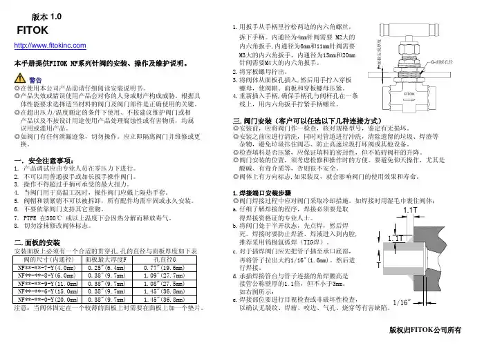
1.用扳手从手柄里拧松两边的内六角螺丝, 拆下手柄。
内通径为4mm针阀需要 M2大的内六角扳手,内通径为6mm和11mm针阀需要 M3大的内六角扳手,内通径为15mm和20mm 本手册提供FITOK NF系列针阀的安装、操作及维护说明。
针阀需要M4大的内六角扳手。
2.将穿板螺母拧出。
警告3.将阀体从面板孔插入,然后用手拧入穿板◎在使用本公司产品前请仔细阅读安装说明书。
螺母,使阀帽、面板和穿板螺母压紧。
◎产品失效或错误使用产品会对你的人身或财产构成威胁。
根据具4.重新插入手柄,确保手柄孔与阀杆孔在一条 体性能要求选择适当材料的阀门及阀门部件是正确使用的关键。
线上,用内六角扳手拧紧手柄螺丝。
三.阀门安装(客户可以任选以下几种连接方式)◎安装前,应将阀门作一检查,核对规格型号,鉴定有无损坏。
◎如阀门有任何泄漏迹象,切勿操作。
应立即隔离阀门并维修或更◎安装之前应进行清洗,同时对管道进行冲洗,清除遗留的垃圾、焊渣等 换。
杂物,避免垃圾拤住阀芯、防止高速垃圾打坏阀或其他设备。
◎检查填料是否压紧,应保证填料的密封性,但不妨碍阀杆的升降。
一.安全注意事项:◎阀门安装的位置,须考虑检修和操作时的方便。
要避免仰天操作,尤其是1. 产品调试应由专业人员在零压力下进行。
酸碱、有毒介质等,否则很不安全。
2. 不可以用普通扳手或加长扳手操作阀门。
◎阀体上有方向标志,如果装反,就会影响阀门的使用效果和寿命。
3. 操作不得超过手柄可承受的最大扭力。
4. 当阀门用于高温工况时,操作阀门应戴上隔热手套。
1.焊接端口安装步骤5. 阀帽和锁紧销不可以被拆卸,所有配件均需牢固或永久安装。
◎阀门焊接过程中应对阀门采取冷却措施。
如焊接时用湿毛巾裹住阀体;6. 不要依靠阀门支持其它重物。
a.仔细了解焊接的程序,焊接必须要是取7. PTFE 在380℃ 或以上温度下会因热分解而释放毒气。
得焊接资格证的专业人士。
8. 切勿涂抹修改阀体标志。
b.将阀门处于半开状态,先点焊,然后焊 死。
INSTALLATION:Check 1. mounting structure making sure it is rigid, level andwell supported. Inspect shaft to insure it is smooth (32 micro-inch finish or better), within commercial tolerances and free of burrs or rough spots.Disassemble and thoroughly clean all parts of the pillow2. block, Housing caps and liner caps are matched to their bases and should not be interchanged. Housing and liners should be interchanged as assemblies only.WARNING: Rust preventatives and solvents can be toxic and/or flammable. Follow directions and safety procedures recommended by their manufacturers.ATTENTION: Liner assembly has critical machines surfaces which are easily damaged. Use care in handling to protect these surfaces. Liner parts should be placed on a soft, CLEAN surface.Position 3. housing base on pedestal so that oil gauge is inthe position specified on the construction drawing. Do not tighten housing base to pedestal . Apply oil to the spherical seats in the housing base.Set liner base in housing base and apply oil to liner bearing4. surface.ATTENTION: Care should be taken when reinstalling coolant pipes. Use pipe sealant and tighten securely. Over tightening may result in liner damage.Apply oil to 5. shaft in the bearing area and set shaft in place.Check alignment 6. of pillow block by noting clearancebetween housing and shaft at each end of the housing—clearance should be uniform within 1/32”. Shim bearing pedestal where possible, otherwise use full length shims under base as required. Alignment of pillow block should be as accurate as possible. The self-alignment feature of the unit is to compensate for normal shaft deflection and possible setting of the supports.Place 7. oil rings around outside of lower liner and over shaft.Peen screws to insure that they are secure. Make sure rings rotate freely on shaft.Thrust Collars 8. , to be used in a fixed unit, should now beinstalled. Remove clamp screws from thrust collars and clean cracked joint with wire brush. Back off set screws to clear inside of collar. Place one collar half on shaft so shaft flinger groove is next to liner base in the non-expansion (fixed) bearing. Rotate collar half around shaft and place other half in position. Bring halves together at joint, making sure match at joint is perfect and insert clamp screws. There should be no offset at collar face. Tap halves together and tighten (Soc Hex) clamp screws alternately and evenly to torque specified in Table 2. Repeat above operation for opposite end of bearing. Assemble two collars on one bearing only . Tap collar up to WARNING: Because of the possible danger to persons(s) or property from accidents which may result from the improper use of products, it is important that correct procedures be followed. Products must be used in accordance with the engineering information specified in the catalog. Proper installation, maintenance and operation procedures must be observed. The instructions in the instruction manuals must be followed. Inspections should be made as necessary to assure safe operation under prevailing conditions. Proper guards and other suitable safety devices or procedures as may be desirable or as may be specified in safety codes should be provided, and are neither provided by Baldor Electric Company nor are the responsibility of Baldor Electric Company. This unit and its associated equipment must be installed, adjusted and maintained by qualified personnel who are familiar with the construction and operation of all equipment in the system and the potential hazards involved. When risk to persons or property may be involved, a holding device must be an integral part of the driven equipment beyond the speed reducer output shaft.INSTRUCTION MANUAL FOR 1-11/16” thru 3-7/16” SLEEVOIL®Plain-Water Cooled Pillow BlocksThese instructions must be read thoroughly before installation or operation.face of lower liner allowing a total clearance of .006”–.012” on sizes 1–11/16” and 1–15/16”, and .008”–.014” on sizes 2–3/16” through 3–7/16”, then tighten (Soc Hex) set screw to torque specified in Table 2. Collar should run parallel to end face of liner within .002”.Apply oil to bearing surface of 9.liner cap . Locate cap in place on lower liner making sure oil ring is free to rotate.The Sleevoil liners 1-11/16” thru 3-7/16” have upper halves that are normally reversible on the lower half. By design, they are not doweled together and therefore not match-marked. Two modifications which require match-marking of these ‘PL-WC’ liners, 1-11/16” thru 3-7/16” are:When using full (Type II) Bronze Thrust Plates • :Since liners are doweled together and machined as an assembly, care must be used to insure match marks are adjacent to each other and identical. The match marks will be on the Bronze Thrust Plate halves for b.t.p. face squareness after machining. Since the liner halves are doweled together, a liner with Type II Bronze Thrust Plates is rigid and does not allow the upper half to self-align to the plunger screw. To compensate for this loss of self-alignment, a special plunger screw washer is required. This special loose washer must be positioned on the upper liner spherical seat and under the plunger screw to insure alignment of liner bore to shaft in operation.When Liners Have a Cylindrical Bore • : Since the locationof the bore centerline to the liner dowels is then rigidly fixed, an upper liner reversed on a lower or interchanged halves from two different liners can severely change the clearances between shaft and liner bore.Tighten 10. housing base to pedestal. Torque bolts to value given in Table 3. Shaft should rotate freely.Thread 11.dust seal and seal spring into groove at end of housing base and around shaft. Hook ends of spring together; taking care not to overstress spring when stretching. Permanent set can cause loss of working load and looseness on shaft; resulting in oil leakage during operation. For size 3-7/16” thread dust seal and seal retainer into groove at end of housing base and around shaft. Slide free end of seal retainer thru clasp and pull tightly. Hold clasp with screwdriver and pull free end of retainer as tightly as possible with pliers. If tightened properly, it will be difficult to move seal sideways. Cut off excess material, and discard it so it won’t drop in housing bottom. If unit is furnished with auxiliary seals, install a second seal on each end.If using End Closure , neoprene discs should be installed at this time. Consult construction drawing for type of seal recommended .Apply Gasket Eliminator to Sleevoil housing base along outer 12.contour of joint. Loosen plunger screw and locate housing cap on base taking care not to damage dust seals or housing gasket. To reduce chances for leakage, a non-hardening sealant may be used under cap bolts. Torque housing bolts to value given in Table 4. The plunger screw must be loose until the housing bolts have been tightened .These Sleevoil ‘PL-WC’ housings have match marks permanently stamped on the water grommet pad starting in June 1988. These match marks permanently insure that parts stay paired and critical orientation of assemblies is maintained.Cap Loaded Bearings: Shaft must be held down to installcap, tighten plunger screw to recommended torque given in Table 4 with shaft held down. Mark position of plunger screw.Loosen plunger screw one complete turn and loosen shafthold down. Then tighten plunger screw while tightening shaft hold-down until plunger screw is tightened to the mark. Donot over-tighten shaft hold-down as this can misalign thebearing. Remove shaft hold-down and tighten plunger screw locknut.NOTE: Do not tighten plunger screw on accompanying base loaded bearing until cap loaded bearing has been installed and hold-down removed.Base Loaded Bearings: Tighten plunger screw to recommended torque given in Table 4 and tighten locknut.The13. oil level gauge may be located any distance from thepillow block by the use of a coupling and pipe of the desired length. The extended pipe must be supported so that itremains straight and perfectly level. Use a spirit level—do not guess. Use pipe sealer on all connections.IMPORTANT: Check and re-torque plunger screw to thespecified torque after 24 hours of initial start-up and then check and retorque periodically as required.Remove all pipe plugs and flush liner bore and housing14.thoroughly with solvent or cleaner. Reinstall pipe plugs using pipe sealer. Tighten securely.Each housing base has predrilled holes for doweling bearing 15.to base plate.LUBRICATION and OPERATIONSince the satisfactory operation of the pillow block depends almost entirely on the oil film being maintained between the shaft and liner bearing surface, it is recommended that a high grade straight mineral oil with rust and oxidation (R & O) inhibitors and anti-foam agents be used. Check equipment specifications for specific recommendations of oil viscosity by equipment manufacturer. Oil viscosity is determined by the equipment manufacturer and normally specified on the construction drawing or in the operating manual. Otherwise, see Table 1. Information regarding qualities and properties of specific oils should be referred to the lubricant manufacturer.TABLE 1—Recommended Oil ViscosityIf not specified by equipment manufacturer.Ambient Temp.Fahr. DuringStart UpSpeed SAE/ISO Oil RequiredBelow -10ºAll Consult Equipment Manufacturer-10º to 32ºAll SAE, 10/ISO3232º to 70ºLowHighLow SAE 20/ISO68 SAE 10/ISO32 SAE 30/ISO100Above 70ºHigh SAE 10/ISO32 for Light LoadsSAE 20/ISO68 for Heavy Loads Use high grade, high quality, well refined petroleum oils of the straight mineral type, with rust and oxidation inhibitor and anti-foam agent only.Table 2SLEEVOIL Size StandardOilCap.Fl.-Oz.COLLARCLAMP SCREW SET SCREWScrewSize(Soc Hex)WrenchTorque(In.-Lbs.)ScrewSize(Soc Hex)WrenchTorque(In.-Lbs.)1-11/1681/4–20NC1605/16–18NC140 1-15/1681/4–20NC1605/16–18NC140 2-3/16105/16–18NC3257/16–14NC350 2-7/16155/16–18NC3257/16–14NC350 2-11/16183/8–16NC5801/2–13NC600 2-15/16183/8–16NC5801/2–13NC600 3-7/16331/2–13NC14255/8–11NC1200Approximate viscosity:SAE 10–183 SUS at 100ºF; 46 SUS at 210ºFSAE 20–348 SUS at 100ºF; 57 SUS at 210ºFSAE 30–489 SUS at 100ºF; 65 SUS at 210ºFISO32 -158 SUS at 100ºF; 44 SUS at 210ºFISO68 -335 SUS at 100ºF; 55 SUS at 210ºFISO100–495 SUS at 100ºF; 66 SUS at 210ºFFill the pillow block with oil to the top of the center circle in the oil gauge. After placing into operation, remove inspection covers and check to make sure oil rings are bringing up oil. Operation should be checked frequently during the first few days. After some running of base loaded bearings only, loosen plunger screw 1/4 turn, then retighten as specified. This will allow the liner to align with the shaft. For cap loaded bearings, follow installation procedure. If noise develops, check alignment of housing, collar runout, plunger screw and all operating parts. Check all points and make sure all screws and nuts are tightened after several days operation. Maintain oil level above bottom of center circle at all times while unit is in operation.Oil Maintenance ScheduleDrain, flush, and refill with oil after 2 to 3 weeks of initial break-in operation. Since the satisfactory operation of the bearing depends entirely on an oil film being maintained between the shaft and the bearing liner surface, it is recommended that an oil analysis be performed at these regular intervals.Every 3 months for 24 hour/day service•Every 6 months for 8 hour/day service•Acceptability of oil should be referred to the lubricant manufacturer. If oil quality is acceptable then repeat this procedure in 3 month intervals. Visually check oil for contamination between oil analysis checks. Oil service life depends upon several factors such as ambient conditions, operating temperature and frequency of bearing starts and stops. It is recommended that the oil be changed at least once per year for unfiltered static applications. Removing contaminants through the use of either the OLF (Oil Level and Filtration) Unit or a circulating oil system can extend oil service life. Consult equipment manufacturer for more information.Oil film temperature in liner during operation should not exceed 180ºF. If in doubt, consult equipment manufacturer.Any question on installation, maintenance, or arrangement of coolant connection inlets and outlets should be referred to the original equipment manufacturer.Table 3SLEEVOILSizeStandardHOUSING/PEDESTAL BOLTSThreadSizeTorque(In-Lbs)1-11/161-15/165/85/8120012002-3/162-7/163/43/4210021002-11/162-15/167/87/8204020403-7/163/42100Table 4SLEEVOILSizeStandardPLUNGER SCREW HOUSING CAP BOLTSWrench Size(Soc Hex)Torque(In-Lb)ThreadSizeTorque(In-Lb)1-11/161-15/165/85/83003007/16–147/16–143603602-3/162-7/165/85/83504001/2–131/2–136006002-11/162-15/165/85/84504505/8–115/8–11108010803-7/165/85003/4–101920Reference Name of Part No. Reqd.Part Numbers1-11/161-15/162-3/162-7/162-11/162-15/163-7/16Non. Exp. Pillow Block1134215134216134217134218134219134220134221 Exp. Pillow Block1132984132985132986132987132988132989132990 Modular Housing1132941132942132943132944132993132994132996 Housing Machining 1133845133848133851133854133857133860133863 13● Housing Bolt4411439411439411112411113411117411147411186 14● Washer4419194––––––15Oil Level Plug2430012430012430012430012430012430012430012 16Drain Plug2430008430008430008430008430008430008430008 17Thermcouple Plug1––––43001243001243001218Thermcouple AdapterBush1––––430081430081430081 24● Gasket Eliminator1427359427359427359427359427359427359427359 26Inspection Cover ☐1405005405005405005405005405005405005405005 27Nameplate1133267133267133267133267133267133267133267 28Oil Gauge1430127430127430127430127430127430127430127 29Oil Gauge Gasket1418110418110418110418110418110418110418110 32Plunger Screw1422393422393422394422395422397422397422398 34Plunger Screw Nut1133368133368133368133368133368133368133368❍Seal Kit1389821389822389823389824389825389826389827 36● Dust Seal2133601133602133603133604133605133606132810 38● Seal Spring2133181133182133183133184133184133185133579 40Oil Ring1130044130045130047130049130050130051130054 43Circ Oil Drain Plug1––––––430016 44Liner Assembly 1133583133584133585133586132959132950132951❍● Brass Elbow2430068430068430068430068430068430068430068 46● Water Pipe2430158430158430162430162430162430162430162 49Grommet2133021133021133021133021133021133021133021 50Grommet Washer2133025133025133025133025133025133025133025 51Grommet Nut2407254407254407254407254407254407254407254❍Thermostat2––––––133116❍Heater2––––––132835❍Flex Water Hose Kit1133344133344133344133344133344133344133344❍End Cover❑❑133981133982133983133984133985133986133987❍Split End Plate ❒❒133124133125133126133125133128133129–❍End Plate Cap Screw ☐4417044417044417044417044417044417044–❍Aux Dust Seal Kit2––––––132811❍Housing End Cap Kit1––––––132542 52Split Thrust Collar ⏹2133250133255133260133260133270133275133280 54Thermostat Plug1––––––430012 56Heater Plug1––––––430012Includes housing cap and base, and parts listed immediately below Housing Machining.Liner assembly includes liner cap and base, and parts listed immediately below.● The parts marked are furnished with the assemblies under which they are listed.❍ Not shown on drawing.⏹ 2 required for non-expansion pillow blocks only☐ 4 required per end plate.☐ Nameplate must be ordered separately ❑ Neoprene disc for use when desired, or installations where shaft does not extend through housing. 1 required, for size 1 7/16” to 2 15/16”. 2 required for size3 7/16”.❒ Auxillary plate for bolting to one or both ends of housing where conditions are extremely dirty. Requires one additional dust seal and seal spring per end plate.Requires special matching on housing.World HeadquartersP .O. Box 2400, Fort Smith, AR 72902-2400 U.S.A., Ph: (1) 479.646.4711, Fax (1) 479.648.5792, International Fax (1) 479.648.5895Dodge Product Support6040 Ponders Court, Greenville, SC 29615-4617 U.S.A., Ph: (1) 864.297.4800, Fax: (1) 864.281.2433All Rights Reserved. Printed in USA.11/09 PRINTSHOP 100© Baldor Electric Company MN3055 (Replaces499959)。
诺托北京总部地址:北京市海淀区西三旗建材城东路8号邮编:100096电话:86-10-82950042/43/45/46 传真:86-10-82920115邮箱:rotochina@ 主页:诺托中国诺托大连办事处地址:大连市中山区宏大路18号万达大厦1804室邮编:116001电话:86-411-82656788 82592121传真:86-411-82592121邮箱:rotodalian@ 诺托沈阳办事处地址:沈阳市东陵区高官台街37号邮编:110161电话:86-24-88444168 88433268 88438658传真:86-24-88423558邮箱:rotoshenyang@ 诺托西南办事处地址:成都市营门口路409-439号B 栋308室邮编:610031电话:86-28-87563829传真:86-28-87563839邮箱:rotoxinan@ 诺托哈尔滨分公司地址:哈尔滨市经济技术开发平房集中区渤海三路一号3栋邮编:150060电话:86-451-86814666 86814777传真:86-451-86814333邮箱:rotoharbin@ 诺托上海分公司地址:上海市闵行区吴宝路255号力国大楼502室 邮编:201101电话:86-21-60906500传真:86-21-60906508邮箱:rotoshanghai@ 诺托青岛分公司地址:青岛市崂山区株洲路69#高新园三期3#邮编:266010电话:86-532-85728903 88703963 88035786 传真:86-532-85754467邮箱:rotoqingdao@ 诺托深圳分公司地址:深圳市龙岗区布吉街道坂田居委南坑村第一工业区A 厂房一楼邮编:518129电话:86-755-83663676 83663146传真:86-755-83663147邮箱:rotoshenzhen@ 诺托天津分公司地址:天津市西青区张家窝工业园汇鑫路14号邮编:300380电话:86-22-23833080 23833082传真:86-22-23833081邮箱:rototianjin@诺托郑州办事处地址:郑州市紫荆山路与东大街交叉口紫燕华庭东座0406室邮编:450007电话:86-371-66321009传真:86-371-66333059邮箱:rotozhengzhou@ROTO FRANK CHINA创造内在价值。

8GREEN LINE•Highest performance in minimum size: the die-cast aluminium casing has a very small section (47 x 32 mm) and can be easily built-in into the frame of curtain walls.•Chain in double stainless steel links.•Chain exit in central position.•Quick and easy installation: the manual closing position regulation is not required, avoiding possible mistake. The stop in closing position is regulated by an electronic limit switch control.•If installed on PVC windows, the profile has to be reinforced.•Electronic stop in the intermediate positions in case of overload.•Supplied with 1,5 m cable (QUASAR ) or 3 m (SYNCHRO QUASAR ) and pivoting brackets.•The installation without brackets is possible for windows with pivoting hinges only if the vent height is at least 1500 mm.•In case of vents with four-bar hinges, please contact our Technical Dept.•24 Vdc version is suitable for installation on Smoke and Heat Extraction Systems in conformity to UNI EN 12101-2 Standard, QUASAR DC approved by Istituto Giordano (test report 243340).•version is available on request for some models.•SYNCHRO QUASAR version is equipped with an integrated speed synchronization control board that allows the mounting of more than one actuator on the same vent, avoiding the installation of an external control panel. AC version: Synchro Quasar AC + max 1 Synchro Quasar DC,DC version: max 4 synchro Quasar DC.•In case of BMS-Building Management System avoid repetitive commands in the same direction. For further information contact our Tech. Dept.•Available on request Synchro version with force level (push or pull) and different speeds (fixed or selectable between maximum and limited speeds).Speed reduction enable quiet actuators.•QUASAR DC F-SIGNAL and SYNCHRO QUASAR DC F-SIGNAL are special versions with opening and closing feedback signal (free potential, maintained contact), activated by the current limit. SYNCHRO QUASAR DC F-SIGNAL is provided with additional cable.•For a higher resistance against atmospheric agents, it is available on request the Quasar DC version with protection class IP32.QUASAR - SYNCHRO QUASARChain actuator - Force in push action 300 N - Maximum stroke 500 mmGREEN LINE 9QUASAR ACQUASAR DC QUASAR DC F-SIGNAL VOLTAGE SUPPLY100 Vac – 240 Vac 24 Vdc ± 10%24 Vdc ± 10%ELECTRIC CONNECTION 3 wires + earth 2 wires5 wiresOPERATION by polarity inversion by polarity inversion STROKE500 mm 500 mm 500 mm FORCE (push and pull action)300N300N300NSPEED~ 15 mm/s ~ 15 mm/s ~ 15 mm/s CURRENT ABSORPTION (with max load)0,4 A – 0,2 A 0,9 A 0,9 A PARALLEL CONNECTION YESYESYESLIMIT STOP Electronic Electronic Electronic SAFETY STOPElectronic Electronic Electronic FEEDBACK SIGNAL Open/close PROTECTION CLASS IP30IP30IP30Part No.GREY RAL 900640837Z 40840C 41327T BLACK RAL 900540838A 40841D 41328U WHITE RAL 901040839B40842E41329VSYNCHRO QUASAR AC SYNCHRO QUASAR DC SYNCHRO QUASAR DC F-SIGNAL VOLTAGE SUPPLY100 Vac – 240 Vac24 Vdc ± 10%24 Vdc ± 10%ELECTRIC CONNECTION 3 wires + earth + 5 wires 5 wires5 wires + 3 wires OPERATION by polarity inversion by polarity inversion STROKE500 mm 500 mm 500 mm FORCE (push and pull action)300 N300 N300 NSPEED~ 15 mm/s ~ 15 mm/s ~ 15 mm/s CURRENT ABSORPTION (with max load)0,4 A – 0,2 A*0,9 A 0,9 A PARALLEL CONNECTION YESYESYESLIMIT STOP Electronic Electronic Electronic SAFETY STOPElectronic Electronic Electronic FEEDBACK SIGNAL Open/close PROTECTION CLASS IP30IP30IP30Part No.GREY RAL 900641316I 41119Z 41319L BLACK RAL 900541317J 41120A 41320M WHITE RAL 901041318K41121B41321N* If connected to a Synchro Quasar DC current, absorption is double10GREEN LINEStainless steel bottom hinged window bracket part No. 40858ULong brackets kit (to be ordered separately)GREY painted RAL 9006 part no. 40941H BLACK painted RAL 9005 part no. 40942I WHITE painted RAL 9010 part no. 40943JAluminium adjustable “Z” bracket for bottom hinged window part no. 41200CPivoting brackets kit (included)Actuators dimensionsSynchro Quasar installation examplesQUASAR - SYNCHRO QUASARGREEN LINE11The instructions for a safe installation are included in the section “SECURITY WARNINGS”SPECIFICATION PROSPECTSElectric chain actuator Ultraflex Control Systems named Quasar with chain in double stainless steel links.Voltage supply: from 100 to 240 Vac or 24 Vdc – Electronic limit stop; electronic stop in the intermediate positions in case of overload. Casing in painted die-cast aluminium with very small section (47x32 mm). Pivoting brackets included.The 100-230 Vac version and the 24 Vdc version are conform to 2004/108/CE, the 100-240 Vac version is conform also to 2006/95/CE directive.Electric chain actuator Ultraflex Control Systems named Synchro-Quasar with chain in double stainless steel links. Suitable for mounting more than one actuators (max 4 actuators) on the same vent.Voltage supply: from 100 to 240 Vac or 24 Vdc – Electronic limit stop; speed control; electronic stop in the intermediate positions in case of overload. Casing in painted die-cast aluminium with very small section (47x32 mm). Pivoting brackets included.The 100-240 Vac and the 24 Vdc version are conform to 2004/108/CE directives, the 100-240 Vac version is conform also to 2006/95/CE directive.。
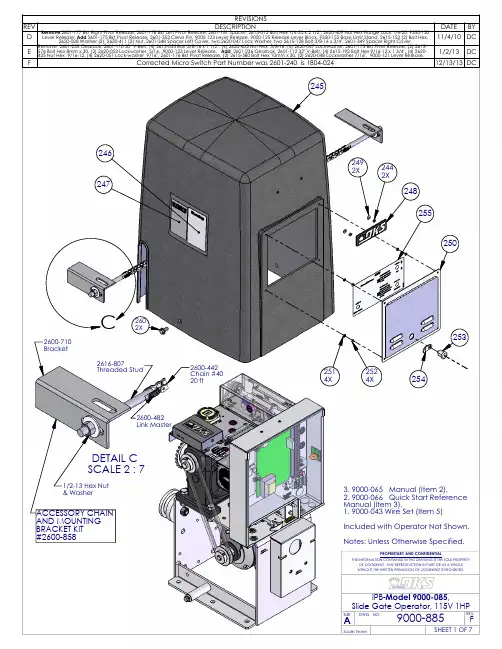
136137135163162156156155160162164128154157IPB 9000-885 Rev E (Model and Movex No. 9000-085) Jan 2, 20131 9000-885 1 EA IPB 9000-085 D2 9000-065 1 EA Manual Installation Slide Gate3 9000-066 1 EA Manual Install Quick Start5 9000-043 1 EA Wire Set 9000 Primary10 9350-150 1 EA Base Stand Slider11 9350-152 1 EA Base Limit Stand12 2615-153 2 EA Bolt Hex 5-16 x 3/4"13 2620-028 2 EA Washer 5/16"14 2620-411 2 EA 5/16-18 Hex Nut Flange Lock15 9350-140 1 EA Panel Lock Cover16 2620-409 4 EA Nut Hex Flange Lock 1/4-2020 2601-237 1 EA Motor 1 H.P. Emerson K55BXKTM21 2601-183 1 EA Pulley 2 1/2 Dia x 5/8 Shaft22 2620-411 4 EA Nut Hex Flange Lock 5/16-1825 2601-222 2 EA Idler Wheel UHMW30 2601-224 2 EA Spacer Idler Model 900031 2620-022 2 EA Washer 5/8" USS32 2615-040 2 EA Bolt Hex Head 5/8-11x3 "33 2620-350 2 EA Nut Center Lock 5/8-1135 9350-125 1 EA Plate Transformer Mount36 2616-000 6 EA Screw Phillips Head 6-32 x 1/440 1200-028 2 EA Outlet Snap-In Leviton 130641 2600-749 2 EA Wire Connector45 2601-236 1 EA Gearbox Clutch 9000 1HP46 1514-020 1 EA Cap Plastic50 2615-192 4 EA Bolt Hex Head 9/16-12 x 1 3/4"51 2620-425 4 EA Nut Hex 9/16-1252 2620-051 4 EA Lockwasher 9/16"55 2601-228 1 EA Sprocket 17 Tooth56 2616-094 5 EA Set Screw 5/16-18X1/4”60 2601-232 1 EA Sprocket 26 Tooth61 2630-011 1 EA Snap Ring 1”65 2601-182 1 EA Pulley 2 1/2 Dia x 3/4 Shaft70 2601-176 1 EA Bracket Pivot Release80 2615-580 2 EA Bolt Hex Head 10mm-1.5 x30mm81 2620-048 2 EA Lockwasher 7/16"85 2601-353 1 EA Clevis Pin90 9000-121 1 EA Lever Release 70 Gearbox91 9000-125 1 EA Release Lever Block92 2902-003 5 EA Nut Nylon Lock 6-3295 2601-207 1 EA Spring Release Lever96 2615-163 1 EA Bolt Hex Head 5/16-18 x 7"97 2601-185 1 EA Shaft Threaded Pivot Release98 2601-187 1 EA Collar Threaded Adjustment99 3004-051 1 EA Nut Panel 1/4 x 18100 2601-190 1 EA Handle Pull Plastic105 1601-060 1 EA Bearing-Sealed 1/2ID x 1 1/8OD 106 2620-470 1 EA Nut Locking Jam 1/2-13110 2601-112 1 EA Belt 1/2" x 32"115 9350-100 1 EA Enclosure Model 9000116 2620-409 4 EA Nut Hex Flange Lock 1/4-20 117 2600-810 15 EA Bushing 7/8 Poke Thru Flaps 120 2600-414 1 EA Terminal Block-2 Position121 2600-410 1 EA Marker Strip Silkscn Both Side 122 3129-002 1 EA Terminal Block Cover 2 Position 123 2616-019 4 EA Screw Phillips Head 8-32 x 3/4 125 2600-439 1 EA Washer Cup - Brass126 2902-010 1 EA Nut Nylon Lock 8-32 Green127 2599-006 2 EA Decal Ground128 2599-014 1 EA Decal Copper130 4001-020 1 EA Terminal 20 Pin131 2616-007 2 EA Screw Phillips Head 6-32x5/8" 132 2902-006 2 EA Nut Nylon Lock 10-32135 4405-010 1 EA PCB Gate Operator136 2616-003 6 EA Screw Phillips Head 6-32x3/4" 137 1860-032 2 EA Washer Nylon Retaining #6150 2343-010 1 EA PCB Current Sensor151 2616-000 4 EA Screw Phillips Head 6-32 x 1/4 154 2902-004 2 EA Nut Nylon Lock 8-32155 2601-193 1 EA Cradle Plastic Release156 2616-018 6 EA Screw Phillips Head 8-32 x 1/2 157 2600-619 5 EA Wire Clp-5/8" Concord 770-1209 158 2902-003 5 EA Nut Nylon Lock 6-32160 9350-105 1 EA Divider Panel Enclosure161 1506-071 1 EA Tone Generator Loud162 1812-005 2 EA Switch Push Button N.O.163 1601-041 1 EA Switch Toggle SPST On-Off 164 2599-096 1 EA Label Push to Operate165 9000-005 1 EA Cover Plastic Screened170 2601-215 1 EA Box Limit Switch Assy171 2620-009 2 EA Washer Split Lock 1/4"172 2905-065 2 EA Screw Phillips Head 1/4-20x1/2 173 2620-002 2 EA Washer 1/4" USS175 2601-130 2 EA Holder Plastic Bearing176 2601-171 2 EA Bearing Sealed 3/8"IDx7/8"OD 178 2616-003 6 EA Screw Phillips Head 6-32 x 3/4 180 2902-003 10 EA Nut Nylon Lock 6-32181 2601-209 1 EA Bumper Rubber185 2601-120 1 EA Shaft 1/2-13 UNC Threaded 190 2620-460 2 EA Nut Bronze 1/2-13 Thread191 2601-125 2 EA Nut Plastic Traveling195 2601-189 1 EA Collar 3/8" ID196 2620-070 1 EA Washer Stainless 3/8ID 1/2OD 199 2616-088 2 EA Set Screw ¼-20x 5/16”200 2601-226 1 EA Sprocket 9 Tooth 35 Chain201 2601-115 1 EA Chain #35 x 24 3/4" w link205 2601-211 1 EA Bracket Limit Nut206 2616-108 2 EA Screw Smooth Shoulder 6-32x3/4 207 2600-857 2 EA Spring-Compression Limits210 1804-024 2 EA Switch Micro211 2900-930 4 EA Standoff Aluminum 1/4" x11/16 212 2904-007 4 EA Screw Round Head 4-40 x 1"215 2601-218 1 EA Bracket Mag Limit Switch216 9310-301 1 EA Bracket Partial Limit Mt. 9310 217 1601-256 1 EA Switch Magnetic Sensor218 2616-031 2 EA Screw Flat Head #0-90x1/4 Slot 219 2620-399 2 EA Nut Hex 00-90 Brass Zinc Plt223 2601-188 1 EA Spring Partial Limit Mag Clip224 2600-368 1 EA Magnet .25"dx.125"th 30DNE1608 225 2601-213 1 EA Cover Limit Switch Box226 2616-001 2 EA Screw Phillips Head 6-32 x 3/8 230 2601-196 1 EA Plate Rec'vr Timer Mount231 2615-002 2 EA Bolt Hex Head 1/4-20x1/2length 232 2620-009 2 EA Washer Split Lock 1/4"235 3130-023 1 EA Terminal Strip 8 dual Row Scrw 236 2599-063 1 EA Label 6500 8 Terminal Mstr-Slv 237 2616-002 6 EA Screw Phillips Head 6-32 x ½238 3129-008 1 EA Cover 8 Terminal Block240 2600-413 1 EA Terminal Block-3 Position241 2599-038 1 EA Label Radio 9310242 2600-810 7 EA Bushing Knock out 7/8244 1897-052 2 EA Gasket245 9350-179 1 EA Cover Operator 9000246 2599-199 1 EA Label Universal247 2599-034 1 EA Label Gate Operator248 2600-732 1 EA Nameplate Plastic DKS249 2802-040 2 EA Washer Push on Clamp250 9350-175 1 EA Frame Door Access251 2902-003 4 EA Nut Nylon Lock 6-32252 2802-002 4 EA Washer #6 SAE253 4001-035 1 EA Lock & Key254 1702-517 1 EA Cam Keyed Lock w/Bend255 2599-215 1 EA Label - Model 9000260 2615-262 2 EA Bolt Whiz Lock 3/8-16 x 3/4261 2601-348 1 EA Spacer Left Cover262 2620-047 2 EA Washer Lock 3/8"263 2615-128 2 EA Bolt Hex 3/8-16 x 3/4"264 2601-349 1 EA Spacer Right Cover265 2599-100 1 EA Sign Warning270 2600-858 1 EA Accessory Box Chain。
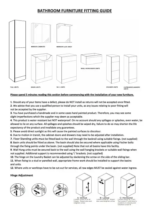
Drawers Remove/InstallTo Remove the Drawer: Follow step 'A' and remove the fastener then follow step 'B'.To Install the Drawer: Follow step 'B' and then follow step 'A' to lock the fastener. Drawer position: If drawer position needs altering follow step 'C' to adjust the screw.LH/RH DOOR OPTIONWOOD BLOCK5mmDRILLBIT1) The door can be either left or right hand opening2) Undo the screws of the hinge plate (attached to the cabinet) Flip the doorover180degrees and refit the hinge plate on the opposite side panel.3) The holes for the door handles are only partly pre-drilled so once the dooris inthe desored position drill through the holes in the back of the door usinga5mm drill bit Top Tip - use a serap block of wood on the front of the door when drilling throughthis will help prevent any splitting. Do not force the drill through.N.B. Drilled doors canont be returnedFix the handle in position using the screws provided×212×2×2×212×2×2×112×1×1please drill the holes according to the hole position mark on the wallplease put the floor standing unit to back to wall, then use a marker pen /pencil to make a drill hole positon directly on wall according to the back panel hole's of unit.111222333Check out our full range of Bathroom FurnitureWide Range of ColoursWhite Bathroom Furniture / White Gloss Bathroom FurnitureGrey Bathroom FurnitureBlack Bathroom FurnitureWalnut Bathroom FurnitureWide Range of StylesBathroom Vanity UnitsBathroom CabinetsBasin & Toilet Furniture UnitsTraditional Bathroom FurnitureBathroom DrawersTall Bathroom UnitsRadiator Covers / Radiator Cabinets。
**订购时请说明颜色编号**Color code must be specified when ordering注:所有带“*”件用于软管及连接组件1147567。
INSTALLATION INSTRUCTIONS安装说明书Deck-Mount Diverter With Handspray 14399T 72636T 缸边式花洒及切换器Deck-Mount Diverter With HandspraySERVICE PARTS 零 件 图Ø65Ø65Ø65Ø52288Ø30~Ø36Ø32~Ø36M a x 32最大32G1/2"G1/2"G 1/2"G 1/2"G 1/2"8935 67105119121Cross Handle 十字把手 14399T/72636T-3Lever Handle 一字把手14399T/72636T-4122236871527O-Ring O 型圈3002770Tee T 型接头864718Plug 塞子864149**Nut连接螺母1051103Nut 螺母1061670**Handspray 花洒(仅用于14399T )1060041**Lever Handle Kit 一字把手组件(仅用于14399T /72636T-4)1060040**Cross Handle Kit 十字把手组件(仅用于14399T/72636T-3)*898324** Hose 软管*834428 Hose 软管833226Hose 软管*1114028**Connection Kit 连接组件*830915Steel Washer 金属垫片830915Steel Washer 金属垫片3002772Fixing Bush 固定接头*870205 Washer 垫片*831289 Washer 垫片831289Washer 垫片831289Washer 垫片837316Washer 垫片831289Washer 垫片1065970**Handspray 花洒(仅用于72636T )1030624Restrictor 限流器*1172476 Guide 导向套*864342 Nut 螺母864342Nut 螺母834792Nut 螺母3004794Valve Extension 加长管3004795Valve 阀芯73089Stem Extension 加长齿套833226Hose 软管831752Check Valve 单向阀3002771Seat 底座安装步骤INSTALLATIONHow To Install The TeePut the washer(2) into the nut(3) of the tee(4). Then connect the tee(4) to one side body(1) of the deck-mount bath faucet as the figure shown.如何安装T 型接头将垫片(2)放入T 型接头(4)的螺母(3)内后,将T 型接头(4)接到用户所选配浴缸龙头的一侧阀体(1)上,如图所示。
Read all instructions completely before installing. Should you have any questions about your installation, please call Customer Service at 440-248-5480. Missing and damaged parts must be reported within 5 days from receipt of delivery.Tools needed for this installation (Not Supplied with Kit)Lever - Pencil or marker - Phillips head screw driver – Electric drill – ½” Standard drill bit for hollow wall installation – Safety glasses – 5/16” Masonry bit for concrete block installation – 1/16” Standard drill bit for stud wall installation – Tape measureParts ListingP/N# Qty Description ______________________ 1700 2 Top Track Sections1701 3 Top Hang Rail & Hardware1705 2 LocBoard Tool Board1710 2 31” Combination Rail1715 1 31” Wire Basket1720 2 31" Wire Shelf1735 20 Assorted LocHook for Tool Board 4 Plastic Hanging Bins4 Assorted Combination Rail Hooks 1 Hex Head Wrench for Hang RailsAll mounting hardware includedWe have included all mounting hardware for hollow and concrete block wall installations. It is not necessary to mount system to wood studs. Each system will require 70 lineal Inches of wall space for mounting and a minimum ceiling height of 7-1/2 feet high for proper clearance.Drill Diameter Listing: Drill diameter sizing for hollow wall installations: Use 1/2” standard drill b itDrill diameter sizing for concrete wall installations: Use 5/16” ma sonry drill bitDrill diameter sizing for wood Stud wall Installations : Use 1/16” standard drill b it for pilot holes Preparation for Top Track Installation: (Image A-1)1. When installing in a corner, leave 1” space between side wall and your top track.2. Determine the maximum height of storage you would like available above your system. (See Fig. A-1). For an 8 foot ceiling; 78” off the floor leaves 18” of storage above and 81” leaves 15” storage above.3. Using a tape measure, mark your desired height off t he floor with a 4” l ong pencil mark.4. (Refer to Fig. A-1 & A-2) Using a level, align top of top track with your pencil mark in step 3. With top track level, mark the center of each hole ’s location on your wall. (Note: Before starting to drill holes always make sure all screw hole locations do not fall in line with electrical wires, duct work or plumbing inside of your wall. If a potential problem exists, reposition and remark screw hole locations.)5.(Fig. A-2) Drill hole locations marked using the correct drill diameter sizing and type listed above. Should you come in contact with wood studs, stop and mark the hole with X and after drilling all other holes come back and drill these holes using a 1/16” bit for pilot hole for wood screws.Attachment of Top Track to Wall Surfaces: (Fig. A-3)6. For hollow walls; (Fig. A-3) Use 2-1/2” long toggle bolts with expanders. Insert all toggle bolts through top track and attach all toggle bolt expanders. Omit toggle bolts that fall in line with X or wood studs. Insert toggle bolts with expanders into holes in wall before starting step 9.7. For concrete walls; use white plastic wall anchors and 2-1/4” long wood screws. Install all plastic wall anchors in all hole locations before starting step 9.8.For wood studs use 2-1/4” long wood screws. Always install wood screws last and there will be no need to use plasticwall anchors.ing a level and holding top track in place tighten one of the end toggle bolts or wood screws until snug. (Allow fortrack movement).10.Making sure top track is still level, tighten toggle bolt or install wood screw on the opposite end until fully secure andthen go back and fully tighten the first toggle bolt.11.Install and fully tighten all remaining toggle bolts or wood screws.Hang Rail Assembly: (Fig. B-1) Assemble (2) 63”long hang rail assembly consisting of 3 parts, (A) Top Slotted section (B) Bottom rail section and (C) Hang rail connector with 2 bolts.Hanging Hang Rails: (Fig. B-2, B-3 and B-4). Note: When installing hang rails, work from left to right or right to left and always installing one hang rail at a time.12.(Fig. B-2 and B-3) Slide each hang rail assembly onto front lip of the top track. Position each hang rail at opposite endsof the track 1/8” (.125”) in from each end.13.Starting from one end, make sure the top outside edge of the hang rail is no greater than 1/8” away from the outsidevertical straight edge of the top track. Using a level, make sure hang rail is flat against wall surface and straight; while holding in place mark the centers of the 3 bolt holes locations onto the wall.14.Drill locations marked in Step 13 using the correct drill bit for your type of wall surface. (Refer to drill diameter listingabove.) Note: Should you come in contact with a wood stud stop drilling and mark hole with an X. After drilling all other holes come back to the X and using a 1/16” bit, create pilot ho le for wood screw installation.Attaching Hang Rails to Wall Surfaces; (Fig.B-4 thru B-6)15.Hollow walls: Use 3-1/2” long toggle bolts with expanders. Remove hang rail from top track, and insert toggle boltsthrough holes in hang rail and attach all toggle bolt expanders. Re-install hang rail and insert toggle bolts withexpanders into holes in wall before starting step 18.16.Concrete walls: Use white plastic wall anchors and 2-1/4” long wood screws. Install all plastic wall anchors in holesbefore starting step 18.17.Wood studs: Use 2-1/4” long wood screws.ing a level and keeping hang rail straight, tighten bolts in order 1) top, 2) bottom and 3) center.Second Hang Rail Attachment: (Fig. B-4 thru B-6)19. Slide the second hang rail to the opposite end of top track. Inside spacin g between hang rails should be 30.75” (30-3/4”).ing your 31” wide Steel LocBoard with square holes and 31” combination rail as spacers. (Refer to Images C-8 and C-9for proper installation.)Install the combination into the inside slots of each hang rail 6 slots from the top and the steel tool board 6 slots from the bottom. Note: Make sure each spacer is installed level and at the same slot level height.ing a level, make sure your second hang rail is straight and that you have easy removal of tool board and combinationrail from both hang rails mark the centers of the bolt holes onto your wall surface.22.Drill out holes for your wall surface and complete installation by following steps 15-18.23.Accessory Installation: (View figures C-1 through C-9.) Al ways make sure you’re installing all accessories level and intothe identical height slots in both hang rails. Binding can occur if not level. All accessories will be installed in the inside slot positions of each hang rail. If accidental binding occurs use soft rubber mallet to help remove accessory and protect the paint.Safety load limits on accessories should never exceed 125 pounds for wire and steel shelves; 18 pounds on a single LocBoard hook;150 pounds on combination rails sections or 35 pounds per combination rail hooks, 75 pounds per Top track hooks, 60 pounds for wire baskets and 75 pounds for recycle and storage sack.Do not place sharp or pointed objects inside of recycle and storage bags. Rips or tears are not covered under warranty.30.375Wire Shelf Bracket installation and hanging installation Wire Bracket installation and hanging installation Metal Shelf Bracket installation and hanging installationSlot on front lip of shelfFig. C-2Fig. C-3Large Tool KeeperinstallationZip and Carry BagFig: C-8 – LocBoard installation Fig. C-9 – Combination Rail installation Warranty information: Triton Products warrants to the original owner that this product is free from defects inmaterial and workmanship for a period of two years from the date of the original purchase. If this product is defective when used as intended under normal household conditions within the specified period, Triton will replace the product, send a replacement part or issue a refund (at our option) when the consumer provides a proof of purchase (either a bill of sale, receipted invoice or other proof that the product is within the warranty period), along with a full description ofthe defect.Liability:Triton Products and/or its Reseller’s liability are limited to 100% of the purchase price of the product.。