518-A型烫金机说明书(开弘机械)
- 格式:doc
- 大小:1.30 MB
- 文档页数:11
印染机械使用说明书一、引言本使用说明书是针对印染机械的操作和维护提供指导,以确保机器的正常运行和延长使用寿命。
在使用印染机械之前,请仔细阅读本手册,并按照指导进行操作。
二、机器概述印染机械是一种用于纺织品印花和染色的专业设备。
本机器具有以下特点:1. 高效性:采用先进的技术和机械结构,提高生产速度和效率。
2. 精确性:具备精确的控制系统,可以产生高质量的印花和染色效果。
3. 可靠性:采用优质的材料和零部件,确保机器的稳定性和可靠性。
三、安全操作指南1. 在操作机器之前,请确保您已经穿戴好相关的防护设备,包括护目镜、手套等。
2. 在上电之前,检查机器的电源和线缆是否完好无损,避免因电气故障引发危险。
3. 在操作机器时,请确保操作区域的安全和整洁,避免杂物和障碍物的存在,以免引发意外。
4. 避免将手或其他物体靠近机器运动部件,防止意外夹伤或其它伤害的发生。
5. 当需要维修或更换机器零部件时,请先将机器断电,并由专业人士进行操作。
四、机器操作步骤1. 开机准备:a. 检查电源和线缆,确保其完好无损。
b. 按照机器的启动顺序打开机器的各个部分。
c. 检查机器的供料系统和排放系统,确保其正常运行。
2. 设定参数:a. 根据不同的印染需求,设定相应的温度、压力、运行速度等参数。
b. 确保设定的参数符合相关的纺织品印花和染色工艺规范。
3. 运行机器:a. 将待处理的纺织品正确放置在机器上,并确保其位置准确。
b. 启动机器,观察运行状态,确保机器正常工作。
c. 随时监控机器运行情况,确保印花和染色效果符合预期。
4. 关机和清洁:a. 结束印染任务后,先将机器停止运行,并切断电源。
b. 清洁机器和工作区域,包括清理机器表面和清除废弃物。
c. 保养机器,润滑机械部件并定期清洗过滤器和喷嘴。
五、故障排除在使用印染机械过程中,可能会遇到一些常见的故障情况。
以下是一些常见故障及其解决方法的示例:1. 机器无法启动:a. 检查电源和线缆是否连接正常。
烫金机工作原理
烫金机是通过升降机构控制热压滚筒的上下运动,使热压滚筒与材料接触,通过加热热压滚筒产生高温和高压,使热传导到烫金膜上,使烫金膜上的箔纸与材料粘合,达到烫金的效果。
具体工作原理如下:
1. 开启热压滚筒加热系统,使热压滚筒表面温度升高到设定温度。
2. 放置待烫金的材料,将烫金膜覆盖在材料上。
烫金膜上的箔纸部分朝向材料。
3. 调节升降机构,使热压滚筒与材料接触。
4. 通过升降机构控制热压滚筒的上下运动,使热压滚筒与材料保持一定的接触时间和压力,使烫金膜上的箔纸与材料接触。
5. 当烫金膜与材料接触时,热压滚筒的高温和高压使烫金膜上的箔纸与材料表面产生接触,箔纸上的金属箔温度升高,胶粘剂软化。
同时,热压滚筒的压力使箔纸、烫金膜和材料之间形成较大的接触压力,使箔纸和材料表面牢固粘合。
6. 一定时间后,升降机构控制热压滚筒回升,使热压滚筒与材料分离。
通过以上工作原理,烫金机可以将箔纸上的金属箔压印到材料表面,实现烫金效果。
铸造设备操作说明书1. 引言铸造设备是用于制造金属或合金制品的重要设备,它具有复杂的结构和操作流程。
本操作说明书旨在提供操作铸造设备的指导,确保操作人员能够正确使用设备,保证生产安全和产品质量。
2. 设备概述铸造设备主要由以下部分组成:熔炉、模具、液态金属处理系统、浇注机械臂、喷砂装置等。
在操作铸造设备之前,务必对设备进行全面了解,并确保设备处于正常工作状态。
3. 安全操作3.1 穿戴个人防护设备在操作铸造设备之前,操作人员应穿戴齐全的个人防护设备,包括耐热手套、防护眼镜、耐热服装和防滑鞋等,以防止热源、金属溅射和其他危险物对人身安全造成伤害。
3.2 检查设备安全装置在开启铸造设备之前,务必检查设备的各项安全装置是否完好,如炉门锁定装置、安全操作开关等。
确保这些装置能够正常工作,以保障操作人员的安全。
3.3 维护操作区域整洁操作铸造设备时,保持操作区域的整洁是十分重要的。
避免杂物、油脂等物质存放在操作区域,以防因此而引发事故。
4. 设备操作流程4.1 熔炉操作4.1.1 装填熔炉材料首先,将预定的金属或合金材料按照指定比例装填入熔炉内,确保熔炉充满了所需的材料。
4.1.2 启动熔炉将熔炉的电源插头插入电源插座,并打开熔炉的电源开关。
根据设备规格,设定熔炉的温度和加热时间,启动熔炉。
4.1.3 温度控制在熔炉加热过程中,通过温度控制装置监测炉内温度,并根据操作要求进行相应的调整,确保炉内温度保持在指定范围内。
4.2 模具准备4.2.1 模具清洁在进行铸造之前,必须对模具进行彻底清洁,确保表面没有杂质和残留物,以防止影响铸件的质量。
4.2.2 涂抹模具防粘剂使用适当的模具防粘剂,涂抹在模具的内部表面,以防止铸件粘在模具上,便于取出铸件。
4.3 浇注铸造4.3.1 接入液态金属处理系统确保液态金属处理系统正常运行,并将其连接到浇注机械臂上,以便进行后续的铸造操作。
4.3.2 浇注金属根据需要浇注的金属或合金种类和数量,操作浇注机械臂将液态金属倒入模具中,确保浇注的过程平稳并避免溅射。
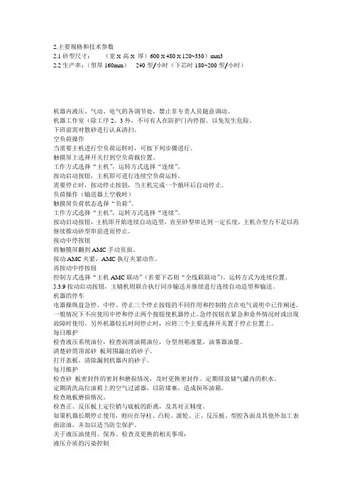
2.主要规格和技术参数2.1砂型尺寸:(宽X高X厚)600 X 480 X 120~330)mm32.2生产率:(型厚160mm)240型/小时(下芯时180~200型/小时)机器内液压、气动、电气的各调节处,禁止非专责人员随意调动。
机器工作室(除工序2、3外,不可有人在防护门内停留。
以免发生危险。
下班前需对散砂进行认真清扫。
空负荷操作当需要主机进行空负荷运转时,可按下列步骤进行。
触摸屏上选择开关打到空负荷载位置。
工作方式选择“主机”,运转方式选择“连续”。
按动启动按钮,主机即可进行连续空负荷运转。
需要停止时,按动停止按钮,当主机完成一个循环后自动停止。
负荷操作(输送器上空载时)触摸屏负荷状态选择“负荷”。
工作方式选择“主机”,运转方式选择“连续”。
按动启动按钮,主机即开始连续自动造型,直至砂型串达到一定长度,主机合型力不足以再继续推动砂型串前进而停止。
按动中停按钮将触摸屏翻到AMC手动页面。
按动AMC夹紧,AMC执行夹紧动作。
再按动中停按钮控制方式选择“主机AMC联动”(若要下芯则“全线联联动”)。
运转方式为连续位置。
5.3.9按动启动按钮,主辅机则联合执行同步输送并继续进行连续自动造型和输送。
机器的停车电器操纵盘急停、中停、停止三个停止按钮的不同作用和控制特点在电气说明中已作阐述。
一般情况下不应使用中停和停止两个按钮使机器停止。
急停按钮在紧急和意外情况时或出现故障时使用。
另外机器较长时间停止时,应将三个主要选择开关置于停止位置上。
每日维护检查液压系统油位,检查润滑油箱油位,分型剂箱液量,油雾器油量。
清楚砂筒顶部砂板周围漏出的砂子。
打开盖板,清除漏到机器内的砂子。
每月维护检查砂板密封件的密封和磨损情况,及时更换密封件。
定期排放储气罐内的积水。
定期清洗高位油箱上的空气过滤器,以防堵塞,造成损坏油箱。
检查地板磨损情况。
检查正、反压板上定位销与底板的距离,及其对正精度。
如果机器长期停止使用,则应在导柱、凸轮、滚轮、正、反压板、型腔各面及其他外加工表面涂油,并加以适当防尘保护。
FM-90001系列操作指南一、用途1、铜钉(螺母)埋植。
2、BOSS孔与装配材料组立,各项塑点熔接与固定。
二、效果减少人力、降低工时、增加产量、提高品质。
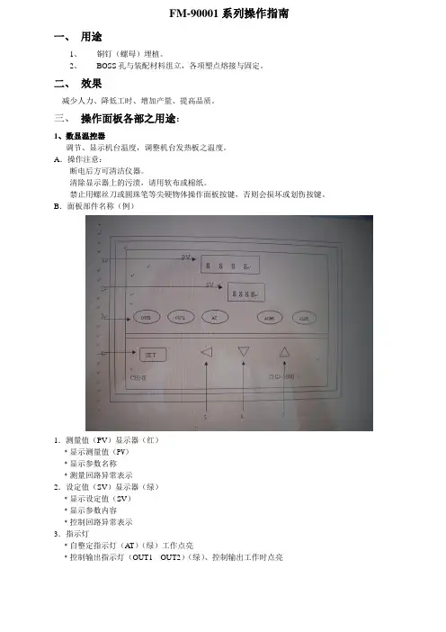
三、操作面板各部之用途:1、数显温控器调节、显示机台温度,调整机台发热板之温度。
A.操作注意:断电后方可清洁仪器。
清除显示器上的污渍,请用软布或棉纸。
禁止用螺丝刀或圆珠笔等尖硬物体操作面板按键,否则会损坏或划伤按键。
B.面板部件名称(例)1.测量值(PV)显示器(红)﹡显示测量值(PV)﹡显示参数名称﹡测量回路异常表示2.设定值(SV)显示器(绿)﹡显示设定值(SV)﹡显示参数内容﹡控制回路异常表示3.指示灯﹡自整定指示灯(AT)(绿)工作点亮﹡控制输出指示灯(OUT1 OUT2)(绿)、控制输出工作时点亮﹡报警输出批示灯(ALM1 ALM2)(红)ALM1:第一报警输出时点亮ALM2:第二报警输出时点亮4.设定键(SET)﹡SV设定:按SET键,SV显示器“SV”可用其余三键修改,按SET键确认并返回至正常显示﹡按SET键3S即可进入参数层5.自动/手动键()﹡在正常显示状态下,作自动/手动切换用﹡在参数设定状态下,作移位键6.减数键(▽)﹡在参数设定状态下,作减数键7.加数键()﹡在参数设定状态下,作加数键2.紧急指示灯:机台中板在上升过程、气压不足与按紧急开关时指示灯显示红色。
3.电源指示灯:显示机台开/关机状态。
4.选择开关(手动、自动):连续作业时选自动功能,手动功能结合手动开关使用。
5.温度开关:开启或关闭机台加热装置。
6.手动开关(上升):当选择开关选择手动时,使用手动上升开关作寸动上升,方便于架模。
7.手动开关(下降):当选择开关手动时,使用手动下降开关作寸动下降,方便于架模。
8.气压指示表:显示气缸使用时的气压,一般为4-6㎏/C㎡。
9.起动模式(单键、双键):根据塑材特性结合滑车控制键作单手、双手作业。
选择单键时右键有效。
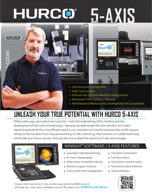
UNLEASH YOUR TRUE POTENTIAL WITH HURCO 5-AXIS Fifteen years ago, we made 5-axis a priority—both the engineering of the machine and the development of the control technology—because we determined that the transition to 5-sidedmachining would be the most effi cient way for our customers to instantly increase their profi t margins. Similar to the transition from manual machining to CNC machining, the transition to 5-sided machining will dictate your future success. Find out why Hurco leads the industry in 5-axis technologies.»High Accuracy Components»Rigid Construction» A Broad Line of 5-Axis Machine Confi gurations»Advanced 5-Axis Control + Features» M ore Standard Memory and Lookahead than the Competition» A utomatic Safe Repositioning»3D Tool Compensation» R otary Axes Centerline Probing»Shortest Angular Traverse» T ool Center Point Management »Tool Path Linearization »Transform Plane » T ool Vector Canned Cycles » T ool Vector Input & Retract »Universal RotaryWINMAXSOFTWARE 5 AXIS FEATURESTo learn which one of our 5-Axis models powered by the MAX5 controlwill make your shop more profi table scan the QR code or visit /5AxisProud distributor of Hurco CNC 800.522.4705HurcoCompanies,Inc.|OneTechnologyWay|Indianapolis,IN46268|800.634.2416|**************|Machines shown with options. Information may change without notice. Transform Plane is the key feature of the Hurco control that makes the transition to 5-axis easy. When it comes to usability, nobody can touch the Hurco control. Designed the way machinists think. Designed to let you determine the best way to approach each part because it’s equally powerful whether you use conversational programming, NC, or CAD/CAM—you can even combine NC and conversational with our signature NC/Conversational Merge feature. Nobody does 5-axis better than Hurco.SR SW SERIES SWIVEL HEAD DCX SERIES 5 AXIS DOUBLE COLUMNVCX SERIES 5 AXIS CANTILEVER BX SERIESVMX42Ui VMX60UiVTXUiVM10UiVMX30UiVMX60SWiVMX84SWi VMX60SRTiVMX42HSRTi DCX32-5Si BX40Ui VCX600i VMX42SWiVMX42SRTi VMX30UHSi VMX42UHSiVM10UHSi。
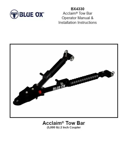
BX4330Acclaim® Tow BarOperator Manual &Installation InstructionsAcclaim® Tow Bar(5,000 lb) 2 Inch Coupler1.Blue Ox tow bars should only be used with vehicles that are towable or have been equipped to be towed.2.Follow towing procedures in the vehicle owners manual.3.Tow with steering wheel in the unlocked position.4.Be sure the front end of the towed vehicle is properly aligned. Misaligned vehicles may cause poor tracking or abnormal wear on the tires.5.The use of safety cables or chains are required by law in most states of the United Statesas well as Canadian territories and provinces. Follow state or territory recommendations.Blue Ox strongly recommends the use of safety cables (BX88196, Class III or BX88197,Class IV) and permanent safety cables (BX88207, Class III or BX88208, Class IV) with all applications of towing. Please refer to their specific installation instructions for more information.6.Check clearance between vehicles in all turning situations. Check the height difference in your towing set up and make appropriate adjustments by following the recommendations of the tow bar instruction manual.7.Rear lighting is required on the towed car. Blue OX offers lighting kits to cover all of your lighting needs. Contact your Blue Ox representative for more information.8.Prior to usage, inspect all towing equipment for cracked welds, missing or worn parts and loose bolts.9.Disconnect the towed vehicle from the towing vehicle before backing up. Do Not Back Up while vehicles are connected! Damage to both vehicles and the towing system may occur. The towed vehicle may jackknife causing abnormal stress to the tow bar, car chassis, baseplate and/or pintle hitch of the towing vehicle. These abnormal stresses may cause damage that may go undetected.10.Avoid sharp turns and rough terrain. Check towing set up after any emergency situation and/or periodically on a long trip.11.Do not use the towed vehicle for storing luggage, etc.; which may cause you to exceed the towing capacity of the tow bar, baseplate, and its accessories.12.Ensure that your towing vehicle is of adequate size to properly control your towed vehicle.The weight and braking capacity should be large enough to handle both vehicles in an emergency situation. Check your towing vehicle manufacturers recommendations for towing, hitch load, and braking capacities. The hitch, ball, motorhome chassis, and safety cables (each individual cable) need to be rated at a minimum for the weight of the vehicle being towed.13.Dealer or installer be certain the user receives these instruction sheets.CAUTION: As with any mechanical product, care should be taken during installation and operation to prevent your fingers from being pinched.DO NOT INSTALL, OPERATE OR USE THIS EQUIPMENT UNTIL THE FOLLOWING OPERATING AND SAFETY INSTRUCTIONS HAVE BEEN READ AND UNDERSTOOD.General Information1.Position the towing vehicle on a level surface with a straight driveway ahead and engage the parking brake. Position the towed vehicle behind the towing vehicle in the approximate towing position.2.Couple the tow bar to the 2” ball on the towing vehicle receiver hitch. Install the coupler pin or padlock thru the coupler lever to secure in place. If needed adjust the coupler to ensure the ball and the coupler ball clamp are making firm contact. (See Coupler Fit Adjustment on page 4)3.Partially extend one leg. Place the triple lug between the attachment tabs on the baseplate, and secure with the 1/2” pin and quick pin. Be sure the 1/2” pin is installed correctly through the attachment tab with the nose towards middle of the baseplate. Repeat for both legs.4.On the towed vehicle, disengage the parking brake and set up the transmission for towing and unlock the steering wheel. Pull forward with the towing vehicle until one or both of the locking handles are engaged and locked (When locked they will “pop” up). If only one locking handle is locked, turn the towed vehicle’s steering wheel towards the unlocked tow bar leg approximately 1/2 to 3/4 turn, before continuing forward. Drive the towing vehicle forward until the second leg locks into place.Hooking Up to Towed VehicleIMPORTANT: Check to ensure both legs are latched properly and pins are secured properly before towing. When properly installed the quick pin ring will snap back onto itself, and the chamfered side will be facing outwards. The steering wheel on the towed vehicle must be unlocked at all times while being towed. Failure to do so will create hazardous driving conditions.CAUTION: It is important that the tow bar coupler be parallel to the ground. The heightfrom the center of the ball to the centerline of the attachment tabs should be approximately 7”. Ifthe tow bar coupler is at an angle, an accidentor damage can occur. The use of a drop/risereceiver is recommended to ensure the couplerstays parallel to the ground.7”Note: The Acclaim ® will only fit on baseplates with a tab width between 23” and 30”1.Utilizing the hooks, attach the cables to a solid part of the chassis on the towed vehicle or the convenience links of the baseplate. Verify the safety snap clicks back against the hook in order to prevent disconnection.2.Adjust slack if needed. Cables should not come in contact with the ground, pintle coupler or the locking handles; damage could occur! DO NOT USE DAMAGED CABLES! Route cables away from the locking handles. Safety cable contact with a locking handle could cause the leg to become unlatched and collapse, leading to major damage to one or both vehicles and towing equipment. DO NOT WRAP SAFETY CABLES AROUND THE LEGS!3.Verify the load capacity of cables or chains used that meets the needs of the towing set up.Safety Cable Installationing a 3/4” socket, tighten or loosen the lock nut until firm contact between the ball and ball clamp.2.Periodically check the tension between the ball and coupler housing and tighten if needed.3.Lightly grease the ball.Coupler Fit AdjustmentLight Spring Ball Clamp HousingLocking LeverUnhooking / Tow Bar Storage Position Figure 1Figure 2Figure 31.Park the towing vehicle with vehicle in tow, in a straight line, on a level surface to ensure minimum pressure is exerted on the tow bar legs. This will aid in the removal of the 1/2” pins.Engage the towing vehicle parking brake. Place the towed vehicle either in park for automatic transmissions or securely in first gear for manual transmissions. Unhook the lighting and safety cables.2.Disengage the leg latches by pushing down on the locking handles. Uncouple the tow bar from the receiver ball. On the driver side, remove the quick pin and 1/2” pin attaching the triple lug to the attachment tab. You may need to tap the 1/2” pin out if there is still pressure on it. Rotate the driver side leg over onto the passenger side leg (Figure 1).3.Align the driver side triple lug onto the holding pin of the passenger side leg. Secure the lug to the pin with the provided hair pin clip (Figure 2).4.Swing the coupler head towards the driver side attachment tab of the baseplate (Figure 3).5.Attach the coupler head bracket to the baseplate attachment tab with the 1/2” pin and quick pin (Figure 4).Figure 4Note: The Acclaim ® will only store on baseplates with tab widths of 23” to 30”Item No. Part No. Description Qty.1.................................84-0055 .............................Leg Assembly, Driver Side .. (1)2.................................84-0056 .............................Leg Assembly, Passenger Side .......................................1BX88154 (Triple Lug Kit)3.................................299-0736 ...........................Offset Triple Lug .. (2)4.................................229-0520 ...........................1/2” Pin . (2)5.................................62-3213 .............................Quick Pin . (2)6.................................201-0645 ...........................1/2”-13 x 2” Hex Head Bolt . (2)7.................................202-0143 ...........................1/2”-13 Essna Jam Nut, ZP .............................................284-0140 (Pins w/Clips Kit)8.................................229-0520 ...........................1/2” Pin . (2)9.................................62-3213 .............................Quick Pin .........................................................................2Additional Kits Available: 11 ...............................84-0089 .............................Tow Bar Washer Replacement Kit .. (1)12...............................84-0102 .............................Tow Bar Rubber Boot Kit . (2)13...............................84-0178 .............................Tow Bar Latch Handle Kit (2)Important:Use only genuine factory replacement parts on your tow bar. Do NOT substitute homemade or non-typical parts. If a bolt is lost or in need ofreplacement, for your safety and the preservation of your tow bar, be sure to use a replacement bolt of the same grade (In most cases it will be Grade 5, please reference the parts list above). Replacement parts may be ordered through your nearest Blue Ox® Dealer or Distributor. Failing to follow and/or altering these installation instructions in either installation or required equipment will void the manufacturer’s warranty.Optional Drop ReceiversPart No. DescriptionBX88128 ....................2” Drop Receiver, 5000 LbBX88129 ....................4” Drop Receiver, 5000 LbBX88130 ....................6” Drop Receiver, 5000 LbBX88131 ....................8” Drop Receiver, 5000 LbBX88132 ....................10” Drop Receiver, 5000 LbTow Bar Maintenance1.This tow bar requires periodic maintenance. It will be subjected to road dirt and weather duringuse. The following tips will help maintain the condition of your new tow bar.2.Keep the tow bar covered when not in use, on or off of the towing vehicle. This will cut down onthe dust and dirt build up on the legs and latches of the tow bar. A BX88156 tow bar cover isrecommended.3.Periodically clean the entire surface of the tow bar with a mild soap and water solution. Wipe drywith a clean cloth.4.Check and replace any loose, worn or damaged bolts, rubber boots or cap plugs.5.Check for cracked welds and loose bolts on the baseplate of the towed vehicle and the hitch onthe towing vehicle.Lubrication1.Approximately once per year or if it is difficult to move the legs in and out you should remove thesmall cable ties holding the rubber boots on the legs and slide the boots back. Wipe clean eachinside leg and apply a light coat of multipurpose grease to insure smooth operation. Secure eachboot back in place with an 8” nylon cable tie.Shop for quality Blue Ox products on our website.Learn more trailer hitches and towing we have.。
热熔机操作说明范文热熔机是一种用于将固态塑料材料加热并熔化成流动状态的设备,常用于塑料制品的生产中。
下面是关于热熔机的操作说明。
一、安全操作1.在操作热熔机之前,要确保设备的电源已经接好地,且电源开关处于关闭状态。
2.在操作之前,要进行相关的安全培训,了解热熔机的使用方法和注意事项。
4.在使用过程中,要随时注意熔融温度的变化,避免过高温度导致设备或工件受损。
二、启动热熔机1.确保设备正常连接到电源,并将电源开关打开。
2.调节热熔机的温度控制器,根据所使用的塑料材料的熔点,设置合适的温度。
3.在设备启动后,等待一段时间,让热熔机达到所设定的温度。
4.在等待期间,可以开始准备工作区,清理工作台,将需要加工的塑料材料准备好。
三、操作步骤1.将需要加工的塑料材料放置在熔融室内。
2.使用顶杆将塑料材料向下压紧,确保材料可以均匀熔化。
3.根据需要,可以适当调节压力和温度,以获得所需的熔融效果。
4.当塑料材料完全融化后,可以开始进行下一步的操作,如注塑或挤出等。
五、关闭热熔机1.操作结束后,将温度控制器调回初始位置。
2.将热熔机的电源开关关闭。
3.清理熔融室内的残留塑料,以免对下次使用造成影响或损坏设备。
4.定期对热熔机进行保养和维护,确保设备的正常运行和寿命。
六、注意事项1.在操作热熔机时,要随时注意温度的变化,避免过高温度导致设备或工件受损。
2.在加工过程中,要严格按照操作规程进行操作,确保操作的安全和准确性。
3.在操作结束后,要及时清理设备和工作区,保持整洁和安全。
4.在操作过程中,如果遇到异常情况或设备故障,应立即停止操作并寻求专业人员的帮助。
以上是关于热熔机的操作说明,希望对使用热熔机的人员有所帮助。
在操作热熔机时要始终保持谨慎和安全意识,确保操作的顺利进行和人员的安全。
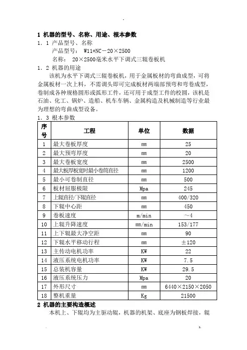
1 机器的型号、名称、用途、根本参数1.1 产品型号、名称产品型号: W11*NC-20×2500名称: 20×2500毫米水平下调式三辊卷板机1.2 机器的用途该机为水平下调式三辊卷板机,用于金属板材的弯曲成型,可将金属板材一次上料,不需调头即可完成板材两端部预弯和弯卷成型,卷制成各种规格圆形或弧形工件,还可用于成型工件的校圆,该机是石油、化工、锅炉、造船、机车车辆、金属构造及机械制造等行业最为理想的弯曲成型设备。
2 机器的主要构造概述本机上、下辊均为主驱动辊,机器的机架、底座为钢板焊接,辊子为锻钢件〔上辊为50Mn,下辊为42CrMo〕,上辊主传动由22KW电机通过行星减速机驱动,下辊由1QJM32-1.0液压马达及齿轮驱动,三个工作辊均为主动辊。
上辊升降运动由安装在底座两端的的油缸驱动,下辊水平移动由安装在底座侧面的水平移动油缸驱动,上辊升降运动的位移量和下辊水平移动的位移量由显示器显示。
为便于成型筒体工件的卸料,机器上辊左端设有液压倾倒轴承体,右端尾部设有平衡拉杆机构,以保证倾倒轴承体倾倒后上辊悬空始终处于平衡状态〔如倾倒轴承体倾倒后上辊不能保持平衡,可调节此机构〕。
机器的上下辊位移采用NC自动调整,使液压系统驱动下的辊子位移的同步精度到达规定值,移动量有数字显示。
整机构造图见图2-1。
3 机器传动系统3.1 主传动机构上辊传动线速度约为4m/min,是由22KW带制动电机驱动行星齿轮减速器,经联轴器直接与上辊联接,带动上辊正反转动,能确保在传动中准确定位,操作方便。
具体构造见图3-1。
下辊传动的线速度约为4 m/min,由液压马达通过齿轮传动使两下辊转动,卷制不同板材筒件的实际线速度不同,由液压系统控制调节。
详见图3-2。
3.2 辅助传动机构上辊升降、下辊水平移动及倒头立起与倒下,为辅助传动系统。
4 液压系统(见系统原理图4-1)本机的液压驱动为开式系统,电机额定功率为7.5KW,额定工作压力为20MPa,用于驱动下辊油马达旋转系统油缸的升降。
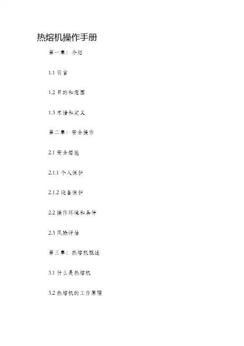
热熔机操作手册第一章:介绍1.1 引言1.2 目的和范围1.3 术语和定义第二章:安全操作2.1 安全措施2.1.1 个人保护2.1.2 设备保护2.2 操作环境和条件2.3 风险评估第三章:热熔机概述3.1 什么是热熔机3.2 热熔机的工作原理3.3 热熔机的组成部分3.4 热熔机的类型和规格第四章:热熔机的准备4.1 选择合适的材料4.2 准备工作区域4.3 连接电源4.4 加热模块和热板的设置4.5 清洁和维护第五章:使用热熔机5.1 操作步骤5.1.1 打开热熔机5.1.2 调整温度和时间5.1.3 放置材料5.1.4 启动熔融过程5.1.5 检查和修整焊接点5.1.6 完成焊接过程5.2 常见问题和解决方案第六章:安全关闭热熔机6.1 关闭热熔机的步骤6.2 等待冷却6.3 清理和维护第七章:故障排除7.1 常见问题及解决方案7.2 外部故障处理7.3 内部故障处理第八章:维护和保养8.1 日常维护8.2 定期检查和保养8.3 零部件更换8.4 故障记录和检修报告第九章:安全操作常见问题解答9.1 如何确保操作安全性?9.2 如何选择合适的材料?9.3 如何调整热熔温度和时间?9.4 如何处理焊接后的问题?结语以上是热熔机操作手册的大纲,手册旨在提供一份详细的指南,帮助操作人员正确、安全地使用热熔机。
通过遵循手册中的步骤和措施,您可以有效地使用热熔机,并提高工作效率。
在使用热熔机之前,请务必完整阅读整个手册,并按照手册中的步骤进行操作。
如有任何疑问或问题,请与设备制造商联系。
祝您工作顺利!。
粘合机500调节说明书
产品概述:
NHG-500型全自动粘合机是正强新一代服装机械设备,适用服装生产中粘合衬与面料粘合,同时还能用于各类面料,理料缩水过程中的烘干烫平,可一机多用,故该机是现代服装生产厂必不可少的专业设备。
适用范围:
床上用品、布艺玩具、皮革、人造皮革、提花布、服装成衣、化纤面料等生产厂家。
产品特点:
体积小易於搬运.
开边式:适合较大裁片,连袖裁片、短纤.
螺旋式拨片,强化裁片拨离之能力,而且裁片不易起泡变形.
本机装有特殊构造之输送皮带,可以排除皮带的偏离,并确保其使用寿命.
迷你压衬机具有特製压力辅助装置,保证最大压力强度至1/㎡.
电子温度调节器,及特製加热设备,将温度差异范围减至最小程度.
採用极完美且能保持热度在一定程度的铁氟龙传动带,而其清洁布杆可随时保持皮带之清洁.
强力散热风扇,降低电子零件处於高温时之损害.
特殊构造使本机器可安装口袋模、裤头喇叭及滚条喇叭
技术参数:
功率50KW
机身尺寸约长1800×宽1000×高1200(视情况而定)净重约210KG。
5. A broad line of 5-axis CNC machines that meet the needs and budget of virtually every shop.> The VMXSRTi Series utilizes a swivel head B-axis and an embedded rotary torque table.> The U-Series features an integrated trunnion table design, which gives you more clearance in Z compared to other brands that simply stick a trunnion table on a 3-axis machine, and allows for heavier parts to be machined while still maintaining stated accuracies. > T he VC Series is our newest 5-axis configuration. The cantilever design of the B-axis trunnion promotes a wider range of parts than the typical trunnion machine. A main advantage of the Hurco VC600i is the trunnion’s ability to tilt a full 110 degrees in both the positive and negative direction while many competitive machines limit the B-axis tilt to 30 degrees.Hurco Companies, Inc. | One Technology Way | Indianapolis, Indiana 46268 | 800.634.2416 | ************** | Since 1968, Hurco has been revolutionizing themanufacturing industry by developing technologythat makes shops more productive and moreprofitable. One of our recent inventions reducescycle time by up to 30 percent (or more dependingupon the complexity of the part) while significantlyimproving surface finish. Learn more at/ultimotionThe 5-AXIS REVOLUTION. Don’t get left behind.Just as Hurco was known for making the transition from a manual machine to CNC easy, we have a reputation for making the transition from traditional 3-axis machining to 5-sided machining easy. Learn more at /take51. M ore chip time + Less setup time = Increased profit margin. B y implementing 5-sided machining instead of cutting your parts on a 3-axis machine, you eliminate flipping parts and all of the time that’s wasted as part of that process.2. Less scrap. Better accuracy.O n a 3-axis machine, each time you flip the part inaccuracies in workpiece placement can become an issue, and you will need to measure parts more often to ensure accuracy.3. E asy learning curve due to the Hurco MAX5 control powered by WinMax®.N obody does 5-axis better than Hurco. Our engineering team has focused on developing features that make programming typical 3-axis parts for 5-sided machining intuitive and easy to learn. See #4.4. Transform Plane Hurco control feature.T ransform Plane essentially changes programming on a 5-axis machining center back to 2.5D programming that you would use on your 3-axis machine. You don’t need to worry about the tilting or rotating. You define your part origin one time, and Transform Plane manages all of the other part origin locations, which makes set up quick and easy. Five reasonsyour next CNC machine should be a Hurco 5-Axis.。
说明书
WF-518-A型气动烫金机
WF-518-A Pneumatic Bronzing machine
注意:使用前请务必详细阅读说明书
感谢您选购文锋系列产品,本公司专业研发、生产烫金机上胶机,公司拥有一
支优良的队伍,以研发、生产制造、销售、服务为一体,以坚实的品质管理,为您提供高性能,实用性强、高精密的系列产品,主导有烫金机、上胶机系列,产品广泛应用于:电子、家电、包装、塑胶、服饰,鞋包,家具汽车等行业。
本公司多年来一支坚持科学管理,批量生产,以高品质的做工和最优惠的价格,深受广大用户的好评和追捧。
一、工作原理
本产品用压缩空气作为动力,发热管作为热源,发热板安装在气缸下方,模具固定在发热板平面上,压缩空气通过起源处理器、电磁阀接入气缸,通过电磁阀通电、断电控制气路的通断,进而控制气缸的升降,达到模具在工件上烙印、烫金的效果
二、主要特点
1.采用气缸做动力执行元件,运动稳定、可靠。
2.工作过程无冲击,可极大地提高工作效率、加工质量和模具寿命。
3.烫印温度,烫印时间,收带时间可以调节。
4.烫印头高度升降可调。
5.自动计数功能。
三、技术参数
工作电压:AC220V 50HZ;
工作气压:0.2-0.8MPA(2-8kg/cm3);
功率:500w
温度范围:0-400℃(建议调温150℃左右)
产品规格:420*420*580mm
机身重量:35kg
包装:单独的纸箱
工作台面:180*180mm
发热板尺寸:80*90mm(有需要其他尺寸可以联系定制)
四、操作步骤
1、请在提货时,当场验视货物,有元器件损坏,请直接和物流工作人员指出并
联系我们,易损部件:气源处理器、按钮。
图(3)
使用注意事项及设备维护
1.安装模板在打印工作台的中心位置。
2不得大范围调节工作面的平衡度。
3身体的任何部分不得放进打印工作台,以免压伤烫伤。
4定期排放空气压缩机的积水,提高气动元件的寿命。
5保持设备的清洁及活动部分的润滑。
6保持设备整洁。
2、拆开运输用的纸箱,在此过程中请注意保护元器件。
3、放置机器到工作台面,确保水平、稳固。
安装运输途中拆下的易损元器件,
检查电线是否松动、脱出。
4、接通气源、电源和脚踏开关
气源的压力不应低于40kgf/cm2,接通气源后将气缸的压力调节为
0.4MPa。
将电源插头插入机体插座,将脚踏开关也插入机体插座即可。
5、温度、烫印时间,卷膜延时、卷膜时间设定
根据被印物品的品种不同,用温度表调节各材料所对应的温度,机器预热时间为15-20分钟。
(不同材料根据不同温度来达到理想效果)烫印温度设定:按下设置按钮”set然后按温度上下键调整温度,达到你所需要的温度后再次按下设置键,即温度调节完毕。
上面显示的为电热板实际显示的温度,即实时温度,下面显示的为你所需要的温度,即为设定温度,当实时温度达到设定温度后,就可以工作了。
图(1)
烫印时间设定:按一次设置键,当【烫印时间】指示灯亮起时,结合移位键【《】
和0-9循环键【▲】,设置烫印时间,时间显示单位为秒,即为0-999.99秒,如图(2)。
卷膜延时设定:按2次设置键,当【卷膜延时】指示灯亮起时,结合移位键【《】和0-9循环键【▲】,设置卷膜延时,时间显示单位为秒,即0-999.99秒,如图(2),卷膜延时尽量设定短点,但是不能设定为零,以免拉断烫金纸。
(卷膜延时出厂为0.01,建议不要更改)
6.气缸无法下压
答:①不足,增加气压;②时间设定为零,增加烫金时间
③脚踏开关和微动开关;④检查电磁阀是否损坏
⑤.排除以上问题为线路板损坏
7.温度失常
答:①如温度表显示0000则电热偶损坏;②加热管损坏,万用表测量是否通路;
③排除以上可能,可能温度表损坏;
图(2)
卷膜时间设定:按3次设置键,当【卷膜时间】指示灯亮起时,结合移位键【《】和0-9循环键【▲】,设置卷膜时间,时间显示单位为秒,即为0-999.99秒,如图(2)。
通过设置卷膜时间设定烫金纸卷带的长短。
清零(RST):长按RST键,即计数清零
6、铜模安装:
铜模背面凃上少量胶水,粘贴在电热板下板下面。
7、色带安装
旋紧左边固定套,取下活动烫带挡盘,装上烫印带,并从左往右饶好,将烫印带头圈如右边收带滚筒即可。
8、电磁阀调试:按下调试按钮可以转换气路控制气缸上下运动(可测试电磁阀
机械结构是否正常);按下调试按钮旋转90°可以锁住气路,便于其他功能的调试。
图(3)
9、气缸调试:通过调节上下螺纹的距离可控制打印工作面的印刷深度,调节完
毕后用2只扳手锁紧螺母防止设备在运转的过程中使其松动。
10、调压阀调节:向上拔出端盖,顺时针旋转增大气压,逆时针旋转则减小气压,调节至指定气压按下端盖确认。
如杯体有积水可向上推动底部
放水。
11、平衡度调节
①在烫金机底部微微松动外围的四个内六角螺丝②通过调节内圈的四个内六
角螺丝调节平衡,调节平衡后松紧外围的四个内六角螺丝,注意不要锁的太
紧,以免将板锁变形
五、常见故障及解决办法
1.印制图案缺失,观察压痕纹路是否受力不均匀。
答:调整机器平衡度(见操作步骤第11条),模板表面是否有胶水
2.压痕纹路清晰,但是图案暗淡模糊
答:不同烫金纸不同材料对应的温度不一样,调整温度。
3.打印的烫金纸易脱落
答:增大压力;增加温度;电化铝和材料不吻合
4.打印的材料凹陷过深/凹陷效果不佳
答:改变温度或者增减压力;改变底部材料的硬度5.完全无法打印或者部分打印
答:铝装反或者跑偏。