
DIN 46228
- 格式:pdf
- 大小:4.86 MB
- 文档页数:4

| WHP WDL 2.5/S
- 1 -
Order No.8013140000
Part designationWDK 2.5 LD 1D 2R 230VAC
VersionComponent terminal, 2.5 mm², Screw connection,
Wemid, dark beige, TS 35
EAN4008190024628
Qty.25 pc(s).
Note, ordering data2.5 mm² conductor with wire end ferrule plus
plastic collar only with collar optimised for
diameter (order No. 1333100000, 500 pcs)
Colour of insulating materialdark beige
Connection directionon side
End plate requiredYes
Explosion-tested version "Ex e"No
Installation adviceTS 35
Insulating materialWemid
Levels cross-connected internallyYes
No. of identical terminals1
No. of levels2
No. of terminal strips per level2
Open sidesright
Operating temperature range- 50 °C, + 120 °C
Product familyW-Series
Type of connectionScrewed
Type of mountingSnap-on
UL 94 flammability rating of insulation materialV-0
VersionTerminal with LED

Extract from the online catalog
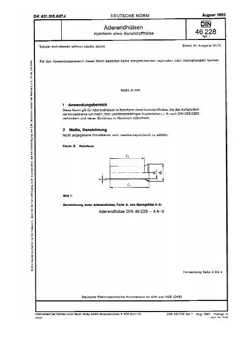
The illustration shows the versions A 1-8 and A 1-10, in redFerrules with plastic sleeve, color range in acc. with
DIN 46228-4: 1990-09
Order No.3200548
Ord designationAI 6 -12 YE
EAN4017918094157
Pack100 Pcs.
Customs tariff74152900
Weight/Piece0,000398 KG
Catalog page informationPage 473 (CL-2005)
Product notes
WEEE/RoHS-compliant since:08/01/2005 AI 6 -12 YE
Please note that the data given here has been taken from the online catalog. For comprehensive information and
data, please refer to the user documentation at . The General Termsand Conditions of Use apply to Internet downloads.
PHOENIX CONTACT Inc., USA
Jul 27, 2006Page 1/5
IMPORTANT : This date is valid for Customers inGermany only. Date Format is MM/DD/YYYY.Please

Electronic timer CT-APS.21
OFF-delayed with 2 c/o (SPDT) contacts
The CT-APS.21 is an electronic timer from the
CT-S range with OFF-delay. It provides 10 time
ranges and a continuous rated control voltage that
enables worldwide use regardless of the supply
voltage.
All electronic timers from the CT-S range are
available with two different terminal versions. You
can choose between the proven screw connection
technology (double-chamber cage connection
terminals) and the completely tool-free Easy
Connect Technology (Push-in terminals).
Characteristics
–Rated control supply voltage 24-240 V AC/DC
–OFF-delay timer with auxiliary voltage
–10 time ranges (0.05 s - 300 h)
–Control input with voltage-related triggering to start timing
–Precise adjustment by front-face operating elements
–Screw connection technology or Easy Connect

Installation InstructionsOriginal InstructionsPOINT I/O Wiring Base AssemblyCatalog Numbers 1734-TB3, 1734-TB3S, 1734-RTB3, 1734-RTB3SEnvironment and EnclosurePrevent Electrostatic Discharge About the AssemblyThe POINT I/O™ wiring base assembly consists of a mounting base (4) and a removable terminal block (RTB)(3). 1734-TB3 uses screw-clamp termination; 1734-TB3S uses spring-clamp terminations.Prepare the WiresInstall the Mounting BaseTo install the mounting base on the DIN rail (Allen-Bradley part number 199-DR1; 46277-3; EN50022), proceed as follows.1.Position the mounting base vertically above the installed units (adapter, power supply or existing module).2.Slide the mounting base down allowing the interlocking side pieces to engage the adjacent module or adapter.3.Press firmly to seat the mounting base on the DIN rail.he mounting base snaps into place.Install the ModuleThe module can be installed before or after base installation. Make sure that the mounting base is correctly keyed before installing the module into the mounting base. In addition, make sure that the mounting base locking screw is positioned horizontal referenced to the e a bladed screwdriver to rotate the keyswitch on the mounting base clockwise until the number required for the type of module you are installing aligns with the notch in the base.2.Verify that the DIN rail locking screw is in the horizontal position.You cannot insert the module if the locking mechanism is unlocked.3.Insert the module straight down into the mounting base and press to secure.