
001EPC网络原理概述
- 格式:docx
- 大小:1.08 MB
- 文档页数:61


3、简述EPC系统的信息网络系统的组成EPC信息网络系统有本地网络系统和全球互联网组成,是实现信息管理、信息流通的功能模块、EPC系统的信息网络系统是在全球互联网的基础上,通过EPC中间件以及对象名称解析服务(ONS)和可扩展标记语言(XML)实现全球“实现互联”1、EPC中间件:EPC中间件是加工和处理来自识读器的所有信息和事件流的软件,是连通识读器和企业应用程序的纽带,主要任务是在将数据送企业应用程序之前进行标签数据校对、识读器协调、数据传送、数据存储和任务管理、2、对象名称解析服务(ONS):对象名称解析服务(ONS)是一个自动的网络服务系统,类似域名解析系统(DNS),ONS给EPC中间件指明了存储产品的有关信息的服务器。
ONS设计和架构都以DNS为基础。
ONS服务是联系EPC中间件和后台EPCIS服务器的网络枢纽。
3、可扩展标记语言(XML):XML是Internet环境中跨平台的依赖于内容的技术,是当前处理结构化信息的有力工具。
XML是一种简单的数据存储语言,使用一系列简单的标记描述语言,已成为数据交换的公共语言。
在EPC系统中,XML用于描述有关产品、过程、环境信息,供工业和商业中的软件开发、数据存储和分析工具使用。
EPC系统使用XML的目标是为物理实体的远程监控和环境监控提供一种简单、通用的描述语言,可广泛应用在货物追踪、自动处理事务、供应链管理、机器监控和物对物通讯等方面。
4、EPC信息服务(EPCIS):利用单一的标准采集和分享信息的方式,为EPC提供一套标准的接口,供各个行业和组织使用。
EPCIS针对中间件传递的数据进行EPCIS标准的转换,EPCIS在构建真正开环的EPC网络、实现各厂商的EPC系统的互联互通起决定性作用。
4、简述EPC系统的工作流程开放性、通用性、可扩展性3、简述EPC编码策略编码原则:唯一性、简单性、可扩展性、保密性与安全性编码类型:64bit、96bit策略:是通过无线射频识别(rfid)标签和其他方式来普遍识别物理对象的识别方案;EPC编码将是新一代的与EAN·UCC编码兼容的新的编码标准,在EPC系统中EPC编码与现行上午GTIN相结合,并不是取代现代现行的条码标准,而是由现行的条码标准逐渐过渡到EPC标准或者未来的供应链中与EPC和EAN·UCC系统共存。
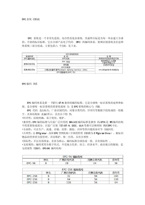
EPC系统的构成EPC系统是一个非常先进的、综合性的复杂系统,其最终目标是为每一单品建立全球的、开放的标识标准。
它由全球产品电子代码(E PC)的编码体系、射频识别系统及信息网络系统三部分组成,主要包括六个方面,见下表。
EPC编码体系EPC编码体系是新一代的与GTIN兼容的编码标准,它是全球统一标识系统的延伸和拓展,是全球统一标识系统的重要组成部分,是EPC系统的核心与关键。
EPC代码是由标头、厂商识别代码、对象分类代码、序列号等数据字段组成的一组数字。
具体结构如表2-2所示,具有以下特性:•科学性:结构明确,易于使用、维护。
•兼容性:EPC编码标准与目前广泛应用的E A N.UCC编码标准是兼容的,GTIN是E P C编码结构中的重要组成部分,目前广泛使用的GTIN、SSCC、GLN等都可以顺利转换到EPC中去。
•全面性:可在生产、流通、存储、结算、跟踪、召回等供应链的各环节全面应用。
•合理性:由EPCglobal、各国EPC管理机构(中国的管理机构称为EP Cglob al China)、被标识物品的管理者分段管理、共同维护、统一应用,具有合理性。
•国际性:不以具体国家、企业为核心,编码标准全球协商一致,具有国际性。
•无歧视性:编码采用全数字形式,不受地方色彩、语言、经济水平、政治观点的限制,是无歧视性的编码。
EPC-96 编码结构当前,出于成本等因素的考虑,参与EPC测试所使用的编码标准采用的是64位数据结构,未来将采用96位的编码结构。
EPC射频识别系统EPC射频识别系统是实现EPC代码自动采集的功能模块,主要由射频标签和射频读写器组成。
射频标签是产品电子代码(EPC)的物理载体,附着于可跟踪的物品上,可全球流通并对其进行识别和读写。

EPC 基础知识介绍1. EPC 网络介绍1.1 浅看GPRS 网络结构(GSM 接入)gprs_gsm.pdf1.2 EPC 网络结构epc.pdf1.3 PCN 网络结构pcn.pdf1.4 GPRS 网络接口gprs_interface.pdf1.5 EPC 网络接口epc_interface.pdf1.6 附着流程Attach Procedure.pdf2. MME2.1 硬件SGSN-MME MkVIII Cabinet, 3-Magazines MkVIII Magazine, Front View.pdf MkVIII Magazine, Side View.pdf2.2 背板Backplane Connectors.pdfPower distribution to all slots1 GbE connections to each slot from the System Control Switch Boards (SCXBs)10 GbE connections to slot 1–24 from the Component Main Switch Boards(CMXBs)Slot positions 1–24 use GEP3 PIUs that use two slots each.2.3PIU(plug-in unit)CMXB3 - Component Main Switch Board, version 3. A PIU with 10 GigabitEthernet Layer 2 switching used for external connectivity and interconnectbetween EGEMs. The CMXB has load balancing on IP port level.SCXB2 - System Control Switch Board, version 2. A PIU with 1 Gigabit Ethernet Layer 2 and Layer 3 switching used for external, and internal connectivitybetween PIUs in the same magazine.GEP3-24GB - Generic Ericsson Processor, version 3. A PIU with a multi core CPU used for generic processing. It may adopt to different types of roles for traffic processing.GEP3-E1/T1 - Generic Ericsson Processor, version 3. A PIU with a multi core CPU used for generic processing. It may adopt to different types of roles including the narrowband with HSL SS7 front end.GEP3-HD - Generic Ericsson Processor, version 3 with Hard Disk. A PIU with a multi core CPU used for generic processing and has a mechanical storage media.GEP3-SSD - Generic Ericsson Processor, version 3 with Solid State Disk. A PIU with a multi core CPU used for generic processing and has flash memory-based storage. The performance of a GEP3-SSD is at least twice that of the GEP3-HD, with the main difference, compared to the mechanical disk, is the increasedIOPS (I/O per seconds) enabling more concurrent reads/writes.2.4APPActive PatchPanel (APP).pdf2.5LEDCommon LEDs.pdf1.Fault LED, Red2.Operational LED, Green3.Maintenance LED, Blue4.Status LED, YellowFault LED, RedOn The PIU has detected a hardware faultOff No hardware fault detectedOperational LED, GreenOn The PIU has power and all internal voltages are present.Fast Blink The PIU is busy with "going to operational". The PIU is booting.Off No powerMaintenance LED, BlueOn The PIU is in a blocked or foreign stateSlow Blink The PIU is indicated as secondary FSBOff Normal operationStatus LED, YellowOn The PIU has detected a hardware or software inconsistencyFast Blink The secondary FSB is synchronizing the file system against the primary FSB.Off No hardware or software inconsistency detected2.6Internal cables1-Magazine MkVIII, Internal Cab 2-MagazineMkVIII, Internal Cab 3-MagazineMkVIII, Internal Cab2.7Health check2.8硬件更换Replacing aGEP.pdf3.EPGSSR 8020或者(M320)In the LTE network, the EPG provides an interface between the MME and PDNs for control plane signaling, and the eNodeB and PDNs for payload.3.1硬件SSR 8020 ChassisLayout.pdfThe chassis is the mechanical enclosure that houses the various cards, fanmodules, and power entry modules (PEMs). The SSR 8020 chassis holds up to 20 line cards or SSC1 cards and up to eight half-height switch-fabric cards (fourSwitch (SW) cards, two Route-Processor/Switch (RPSW) cards and twoAlarm/Switch (ALSW) cards.)3.2板卡类型3.3逻辑结构Platform LogicalArchitecture.pdf3.4EPG应用结构The EPG application consists of control plane and user plane running on the SSC1s. An allocation of the application types on the installed SSC1s takes place during application startup. Based on configuration, each installed card isassigned as a Control Processing Board (CPB) or Packet Processing Board (PPB).During startup, one of the SSC1s configured as a CPB takes on the role of the Global Session Controller (GSC). The remainder of the CPBs function as PGW Session Controllers (PSCs), SGW Session Controller (SSCs), or standby CPBs.Similarly during startup, SSC1s assigned as PPBs take on the role of PacketProcessor (PP) and L2TP Packet Processor (TPP) applications or standby PPBs.3.5EPG应用和接口的对应关系Application Typeswith Supported GPRS3.6Health checkHealth Check.pdf3.7硬件更换Replacing an EPGBoard.pdf。