STEREOSCOPIC SCANNER IN QUALITY CONTROL object, e.g. printed circuit board z y
- 格式:pdf
- 大小:293.49 KB
- 文档页数:6
Reprint, Proc. Conf. 'Quality Control by Artificial Vision', Trois-Rivières, Québec., Canada, May 1999
QCAV99Reprintbc.doc 1/6STEREOSCOPIC SCANNER IN QUALITY CONTROL*
Dr. Richard Schubert
STEREOSCOPIC SCANNING; 3D in Industry & Multimedia
Max-Planck-Straße 5, 12489 BerlinTel: +49 30 6789 2586 Fax: - 2587, Mobil: +49 172 3235121www.stereoscopicscanning.de; schubert@stereoscopicscanning.de
scanning arrayglass ( = projection plane)
virtual center ofprojection(= line in space)projection lines
position A (right eye)position B (left eye)
housingposition A(right eye) position B(left eye)object, e.g. printed circuit board
object, e.g. z
y
x
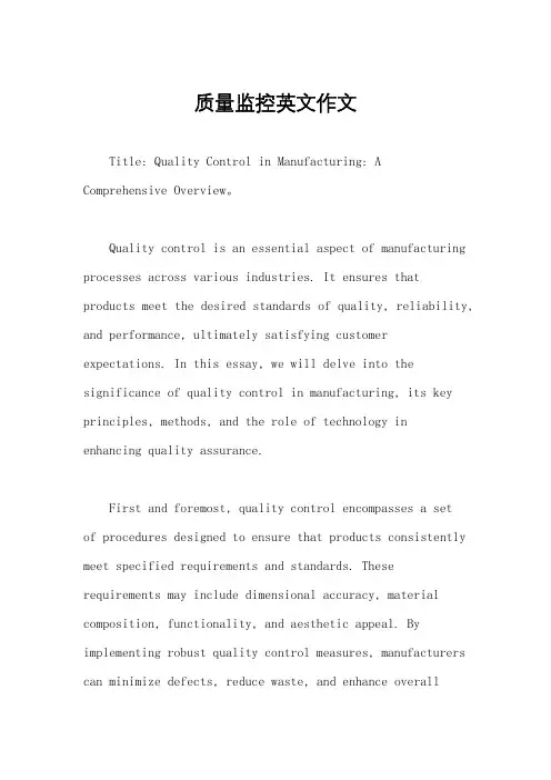
Fig. 1 Simplified optics of a flatbed scanner
Abstract - A very simple method of makingstereoscopic image pairs from small objects bymeans of flatbed scanners has been recentlydeveloped. Due to the non-parallel optics ofmodern flatbed scanners using CCD-elements,objects can be scanned with slightly differentviewing angles by simply putting them on differ-ent lateral positions on the glass surface. As aconsequence of the high resolution and the goodoptical properties of modern flatbed scanners,this method is particularly well suited forapplications in quality control. After a briefdescription of the principle, a new low cost stereo/ 3D scanner based on this principle is presented.1. THE PRINCIPLE OF STEREOSCOPIC SCANNING
Due to their great depth of focus, which is in the order ofa few centimeters, modern flatbed scanners can be usednot only for scanning printed paper, but also for scanningthree-dimensional objects. Since they use CCD-elementsas light sensitive elements, which are much smaller thanthe glass surface, special optics are needed. Fig. 1 givesa simplified view of these optics. In the direction ofmotion of the scanning bar (x) objects are scannedaccording to a parallel projection, as is well known fromtechnical drawings. Perpendicular to this direction (y)the projection lines are diverging, giving a pointprojection, as it is known for example from the humaneye. Thus, flatbed scanners have a very interestingprojection geometry, combining the properties of parallelReprint, Proc. Conf. 'Quality Control by Artificial Vision', Trois-Rivières, Québec., Canada, May 1999
QCAV99Reprintbc.doc 2/6and of point projection. Exact measures of the scannedobjects can be taken without any corrections in thedirection of motion of the scanning bar. For all otherdirections, the exact geometry must be taken intoaccount. At first glance one could suppose that a parallelprojection in both directions would be much better. For alot of applications this seems to be the case. But thediverging projection lines in the direction perpendicularto the motion of the scanning bar give the possibility toscan objects with slightly different viewing angles bysimply putting them on different positions along y on theglass surface of the scanner. In this way one gets theseemingly paradoxical and thus not presumed possibilityof scanning objects in three dimensions on a flatbedscanner, which has first been published in [1] and whichwill be explained on different examples in the nextchapter. 1
2. RESISTORS AND ROSES
Fig. 2 Biscuits in a Box scanned with a conventional flatbed scanner in top down orientation. Two neighboring boxesgive a stereoscopic image when viewed with crossed eyes.
The box in fig. 2 has been scanned in five differentpositions along y (s. fig. 1) directly beneath the glasssurface of a conventional flatbed scanner in upsidedown orientation. The box has a width of 8 cm and thusis much bigger than the distance between the adjacentscanning positions, which had been chosen to be about2.5 cm. Nevertheless, in the picture above one cansimply imagine looking simultaneously at the box in thedifferent scanning positions through the glass surface.Looking at the lateral walls of the box, one clearly seesthe different viewing angles for the different scanningpositions. Referring to fig. 1, it is clear that it isnecessary to look at adjacent boxes with crossed eyes inorder to get a stereoscopic impression. Once havingsucceeded in seeing one box stereoscopically, it ispossible without any problems to move the eyes alongthe whole row without losing the stereoscopic im-pression. In this way, the whole picture with the fiveboxes behaves like an autostereogram, which were in themedia a few years ago ('Magic Eye'). The five singlepictures give four stereoscopic image pairs. One reallyhas the impression of looking into four adjacent boxes,along the line of symmetry. As the boxes have a width of8 cm and have been displaced only 2.5 cm betweendifferent scans, adjacent walls of neighboring boxesappear not to be parallel. As a consequence, the right andthe left wall of one box also seem not to be parallel incontrast to what they really are.