CAN232MB CAN总线协议转换器用户手册
- 格式:pdf
- 大小:1.02 MB
- 文档页数:29
利用CAN232B转换器组建CAN控制网络
一、引言
由于RS232 通讯距离短(根据EAT/TAI-232 标准,仅为15 米),而且,只
能进行点到点通讯,不能直接组多点通讯网络。
为了延长RS232 的通讯距离,并将RS232 节点组成通讯网络,目前广泛使用RS232/RS485 信号转换器。
但是,由于RS485 通讯本身的局限性,在实际应用中存在许多不足:总线效率低、系统的实时性差、通讯的可靠性低、网络工程调试复杂、传输距离不理想、单
总线可挂接的节点少、应用不灵活等。
本文介绍一种方法,可以将RS232 通讯网络转换成CAN 通讯网络,以更好
地解决用户建立远程通讯网络的问题。
二、CAN 总线特性
CAN-bus(ControllerAreaNetwork)即控制器局域网。
目前,CAN-bus 是应用最广的现场总线国际标准之一。
CAN-bus 是一种多主方式的串行通讯总线,可以实现较高通讯速率、高抗电
磁干扰性,而且能够检测出产生的任何错误,以保证实时通讯的可靠性。
CAN-bus 总线具有以下特性:
低成本的现场总线;极高的总线利用率;很远的数据传输距离(长达
10Km)或高速的数据传输速率(高达1Mbps);可根据报文的ID 决定接收或
屏蔽该报文;可靠的错误处理和检错机制;发送的信息遭到破坏后,可自动重发;节点在错误严重的情况下具有自动退出总线的功能;
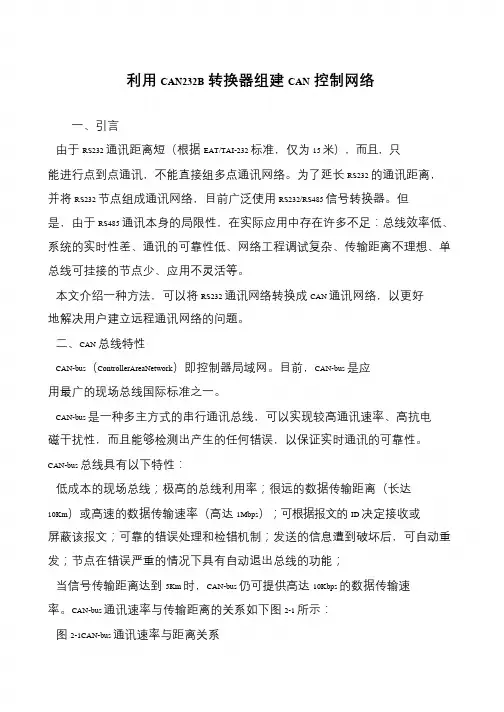
当信号传输距离达到5Km 时,CAN-bus 仍可提供高达10Kbps 的数据传输速率。
CAN-bus 通讯速率与传输距离的关系如下图2-1 所示:
图2-1CAN-bus 通讯速率与距离关系。
UT-2506ARS-232/485转CANBUS智能协议转换器使用说明书一、产品概述UT-2506A是一款高性能RS-232/485转CAN-bus总线通讯协议转换器。
转换器支持RS-232/485和CAN-bus之间的互联互通;RS-232/485支持600-230400bps波特率,CAN-BUS支持5kbps-1Mbps的通讯速率;且转换器支持三种数据转换模式:透明转换、透明带标识转换、Modbus协议转换。
进一步扩展了该转换器的应用范围。
UT-2506A转换器提供配置工具,用户可以灵活设置UT-2506A转换器的接口参数。
工业级高标准设计;CAN通讯接口和系统之间隔离,具备一定的抗干扰和防浪涌能力,广泛应用于工业控制、数据通讯系统。
二、产品技术参数✧支持CAN-bus与RS-232/485的双向数据传输✧支持CAN2.0协议✧集成1路CAN-bus通讯接口,支持5Kbps-1Mbps通讯速率✧集成1路RS-232/485通讯接口,支持600bps-230Kbps通讯速率✧提供三种数据转换模式:透明转换、透明带标识转换、Modbus协议转换✧工作电压:12-36V DC✧工作电流:≤ 150mA@12V✧工作温度:-40~+85℃✧储存温度:-40~+85℃✧工作湿度:5~95%(无凝露)✧储存湿度:5~95%(无凝露)✧隔离电压:1000VDC三、指示灯PWR:红色,电源指示灯;供电正常时长亮。
232TX:绿色,通讯指示灯;当串口对外发送数据时,指示灯闪亮,发送完成熄灭。
232RX:黄色,通讯指示灯;当串口接收到数据时,指示灯闪亮,接收完成熄灭。
CANTX:绿色,通讯指示灯;当CAN对外发送数据时,指示灯闪亮,发送完成熄灭。
CANRX:黄色,通讯指示灯;当CAN接收到数据时,指示灯闪亮,接收完成熄灭。
四、引脚定义(1)CAN接口定义(2)RS-232/485接口定义引脚号引脚名称引脚说明1 CANH CAN-H信号连接端2 CANL CAN-L信号连接端3 RES- CAN匹配电阻端一4 RES+ CAN匹配电阻端二5 RESET 复位(低有效)6 GND 信号地7 GND 信号地8 SET 设置脚(低有效)9 VIN 电源输入正极10 GND 电源输入负极引脚号引脚名称引脚说明1 485+ RS485-A2 485- RS485-B3 GND 信号地4 RXD RS232接收5 TXD RS232发送6 GND 信号地7 GND 信号地8 GND 信号地9 GND 信号地10 GND 信号地五、产品实物图六、结构尺寸。
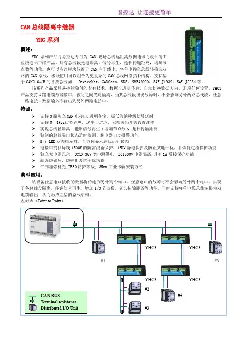
GCAN-202工业级以太网-CAN转换器用户手册文档版本:V3.60(2018/07/18)修订历史版本日期原因V1.002013/06/16创建文档V2.012013/12/20修正设备工作参数V3.122016/09/01添加部分参数V3.502017/01/10添加在线修改波特率功能V3.512017/06/19添加部分参数V3.522017/09/30修正部分参数V3.602018/07/18调整文档结构目录1.功能简介 (4)1.1功能概述 (4)1.2性能特点 (4)1.3典型应用 (5)2.设备安装 (6)2.1设备尺寸 (6)2.2接口定义及功能 (7)3.设备使用 (9)3.1与PC连接 (9)3.2与以太网连接 (10)3.3与CAN-bus连接 (12)3.4CAN总线终端电阻 (13)3.5系统状态指示灯 (13)4.CANet Config软件使用 (15)4.1恢复出厂设置 (15)4.2GCAN-202连接 (15)4.3配置通讯基本信息 (16)4.4配置完成 (18)4.5保存/加载配置文件 (19)4.6升级CANet固件内核(此功能请在指导下使用) (19)5.CANet简易测试软件使用 (21)6.网络调试助手使用方法 (22)6.1调试前准备工作 (22)6.2TCP Server模式通信测试 (23)6.3TCP Client模式通信测试 (24)6.4UDP模式通信测试 (25)6.5CAN口状态的TCP通知数据格式说明 (26)7.GCAN-202在线修改波特率功能 (27)7.1功能说明 (27)7.2格式说明 (27)7.3发送举例 (27)8.二次开发 (28)9.技术规格 (29)10.常见问题 (30)附录A:CAN2.0B协议帧格式 (31)附录B:GCAN-202(CANet)数据流定义 (33)1.功能简介1.1功能概述广成科技GCAN-202(CANET-II)是集成2路CAN接口、1路以太网接口的高性能型CAN-bus总线通讯接口卡。
1.概述CAN(Controller Area Network)总线是德国BOSCH公司为解决现代汽车中众多控制与测试之间的数据交换开发的一种串行数据通信协议,是一种多主方式的串行通信总线。
CAN总线是一种开放式、数字化、多点通信的控制系统局域网,具有通信速率高、传输时间短、传输距离远、纠错能力强、控制简单、扩展能力强以及性价比高等特点,是目前国际上应用最广泛的现场总线之一。
基于CAN总线的CAN控制器具有完成CAN总线通信协议所要求的全部必要功能,因此CAN控制器与其它微处理器的接口成为设计CAN总线系统的首要工作。
实际中很多设备带有RS-232接口,为了方便具有RS-232接口的设备与CAN总线的数据通信,本文完成了基于单片机控制的CAN总线与RS-232转换器电路设计和软件设计,实现了CAN总线数据与RS-232接口设备的数据传输。
2.基于单片机控制的CAN总线与RS-232转换器电路设计CAN总线与RS-232转换器电路包括:主控制模块、RS-232接口转换电路和CAN控制模块3个主要部分。
主控制模块的功能是处理CAN总线以及RS-232接口的数据通信和控制,本设计应用AT89C51完成对转换器各个接口的控制,实现CAN总线和RS-232接口两种协议数据帧的转换,使用带有SPI总线接口的X25045实现硬件看门狗功能。
主控模块电路如图1所示。
RS-232接口电路由MAX232芯片构成,实现将单片机串口的TTL电平与RS-232电平的相互转换,完成RS-232接口信息的输入输出传输。
CAN控制器模块,主要完成CAN协议的物理层和数据链路层协议的实现。
其中物理接口采用PCA82C250芯片实现物理层的电平转换和传输。
CAN控制器使用SJA1000芯片,完成数据链路层功能,实现CAN总线信息的输入输出传输。
AT89C51是CAN总线与RS-232转换器的控制器,提供以下标准功能:4k字节Flash闪速存储器,1000次可擦写周期,三级加密程序存储器,128字节内部RAM,32个I/O口线,两个16位定时/计数器,一个5向量中断结构,一个全双工串行通信口,片内振荡器及时钟电路。
USB to RS232 AdapterUser’s Manual34000212 Rev0Warnings (3)Introduction (4)USB to RS232 Adapter Package Contents (4)Setup Procedure (5)Setup Procedure for Windows 98, ME, and 2000 (5)Setup Procedure for Windows XP (10)Obtaining Technical Assistance (13)Limited Product Warranty (14)NOTICE: This equipment has been tested and found to comply with the limits for a “Class A” digital device, pursuant to Part 15 of the FCC rules. These limits are designed to provide reasonable protection against harmful interference when the equipment is operated in a commercial environment. This equipment generates, uses and can radiate radio frequency energy and if not installed and used in accordance with the instruction manual, may cause interference to radio communications. Operation of this equipment in a residential area is likely to cause harmful interference, in which case the user will be required to correct the interference at the user’s own expense.This digital apparatus does not exceed the “Class A” limits for radio noise emissions from digital apparatus set out in the Radio interference regulations of the Canadian Department of Communications.TrademarksMicrosoft, MS, MS-DOS, XENIX are registered trademarks and Windows, Windows NT, LAN Manager, and Win32 are trademarks of Microsoft Corporation.Note: Notes contrast from the text to emphasize their importance.Warning: These messages alert you to specific procedures or practices; serious consequences may result including injury if you disregard them.Copyright 2002Para Systems, Inc.Unauthorized reproduction prohibited.Monitoring and managing a UPS through USB can be accomplished by using the MINUTEMAN USB to RS232 Adapter cable. Simply connect the RS232 end of the USB to RS232 Adapter cable to one end of the RS232 cable that comes with the UPS. Connect the other end of the RS232 cable to the DB9 port on the UPS. Connect the USB end of the USB to RS232 Adapter cable to the computer’s USB port. Once the USB driver software is loaded, the UPS can be monitored and managed by the MINUTEMAN SentryII power management/diagnostic software without tying up a serial port on the computer.USB to RS232 Adapter CableUSB to RS232 Adapter Package ContentsThe contents of your package are:7USB to RS232 Adapter Cable7 3.5” Floppy DisketteThe 3.5” Floppy Diskette contains the USB device driver, USB setup software, and the User’s Manual.Setup Procedure (Requires Windows 98, ME, 2000, or XP)The following items must be obtained before attempting to setup the USB to RS232 Adapter: UPS with the RS232 cable, RS232 Adapter with the USB cable attached (provided), the USB Driver/USB setup file (enclosed diskette) and a PC with Windows 98 or higher.Setup Procedure for Windows 98, ME, 20001. Connect the USB end of the USB to RS232 Adapter Cable to the USB Port on the computer.2. Connect the RS232 end of the USB to RS232 Adapter Cable to one end of the RS232 Cable.3. Connect the other end of the RS232 Cable to the DB9 port on the UPS.4. Plug the UPS’s power cord into the AC wall outlet.5. Turn on the UPS.6. Turn the computer on and let it boot-up.7. Insert the floppy diskette with the USB Driver/USB setup files into the appropriate drive.8. Windows will display the following message (first time only):New Hardware FoundUSB DeviceWindows has found new hardwareand is locating the drivers for it.9. The Hardware wizard will guide you through installing the USB Driver. Click Next.10. The Hardware wizard will search for the best USB Driver. Click Next.11. Check, Specify a location. Click Browse.12. Open the appropriate 3.5” Floppy Drive. Open the USB folder. Open the Driver folder. Click OK.13. Windows will search for the new USB Driver. Click Next.14. Windows has found the USB Driver for the USB device. Click Next.15. Windows has found the best Driver for this USB device. Click Next.16. Windows is copying the USB Driver files to your “C:” drive. Click Next.17. Windows is finished installing the USB Driver. Click Finish.18. On the Desktop, right click “My Computer”. Open Properties.19. Open the Device Manager.20. Open Ports (COM & LPT). This tells which com-port the USB to RS232 Adapter is using. Click OK.20. Start the SentryII/Power Monitoring Software. Open settings and change the com-port to the appropriate com-portfor the USB to RS232 Adapter.21. The Setup Procedure is complete.Setup Procedure for Windows XP1. Connect the USB end of the USB to RS232 Adapter Cable to the USB Port on the computer.2. Connect the RS232 end of the USB to RS232 Adapter Cable to one end of the RS232 Cable.3. Connect the other end of the RS232 Cable to the DB9 port on the UPS.4. Plug the UPS’s power cord into the AC wall outlet.5. Turn on the UPS.6. Turn the computer on and let it boot-up.7. Insert the floppy diskette with the USB Driver/USB setup files into the appropriate drive.8. Windows will display the following message (first time only):9. The Hardware wizard will guide you through installing the USB Driver software. The Hardware wizard will install theUSB driver software automatically. Click Next.10. The Hardware wizard is installing the USB driver software.11. The Hardware wizard has finished installing the USB driver software. Click Finish.12. The System Settings have been changed. You must restart the computer before the new settings will take effect.Click Yes.13. Once the computer has rebooted, on the desktop, right click on My Computer. Open properties. Open the HardwareTab. Open the Device Manager.14. Open Ports (COM & LPT). This tells which com-port the USB to RS232 Adapter is using.15. Close the Device Manager.16. Start the SentryII/Power Monitoring Software. Open Settings and change the com-port to the appropriate com-portfor the USB to RS232 Adapter.17. The Setup Procedure is complete.Obtaining Technical AssistanceFor Technical Support on the Web, please visit the Support section of our Web site or visit our online Discussion Forum at In order to diagnose the problem you are having, our technicians need the following information from you. Installation Site:CompanyName:Address:State: ZIP code:City:ContactName:Person’sNumber:PhoneComputer System:version:andOperatingSystemManufacturer:SystemNumber:ModelSystemUPS:Name/Number:ModelSerial Number:ofoption:TypeWhat are the symptoms?Technical SupportPlease have the information listed above ready when you contact us. You can reach us by calling:Phone: 1-972-446-7363Fax: 1-972-446-9011LIMITED PRODUCT WARRANTYPara Systems Inc. (Para Systems) warrants this equipment, when properly applied and operated within specified conditions, against faulty materials or workmanship for a period of three years from the date of original purchase by the end user. For equipment sites within the United States and Canada, this warranty covers repair or replacement of defective equipment at the discretion of Para Systems. Repair will be from the nearest authorized service center. Replacement parts and warranty labor will be borne by Para Systems. For equipment located outside of the United States and Canada, Para Systems only covers faulty parts. Para Systems products repaired or replaced pursuant to this warranty shall be warranted for the remaining portion of the warranty that applies to the original product. This warranty applies only to the original purchaser who must have properly registered the product within 10 days of purchase.The warranty shall be void if (a) the equipment is damaged by the customer, is improperly used, is subjected to an adverse operating environment, or is operated outside the limits of its electrical specifications; (b) the equipment is repaired or modified by anyone other than Para Systems or Para Systems-approved personnel; or (c) has been used in a manner contrary to the product's operating manual or other written instructions.Any technical advice furnished before or after delivery in regard to use or application of Para Systems’s equipment is furnished without charge and on the basis that it represents Para Systems’s best judgment under the circumstances, but it is used at the recipient's sole risk.EXCEPT AS PROVIDED HEREIN, PARA SYSTEMS MAKES NO WARRANTIES, EXPRESSED OR IMPLIED, INCLUDING WARRANTIES OF MERCHANTABILITY AND FITNESS FOR A PARTICULAR PURPOSE. Some states do not permit limitation of implied warranties; therefore, the aforesaid limitation(s) may not apply to the purchaser. EXCEPT AS PROVIDED ABOVE, IN NO EVENT WILL PARA SYSTEMS BE LIABLE FOR DIRECT, INDIRECT, SPECIAL, INCIDENTAL, OR CONSEQUENTIAL DAMAGES ARISING OUT OF THE USE OF THIS PRODUCT, EVEN IF ADVISED OF THE POSSIBILITY OF SUCH DAMAGE. Specifically, Para Systems is not liable for any costs, such as lost profits or revenue, loss of equipment, loss of use of equipment, loss of software, loss of data, cost of substitutes, claims by third parties, or otherwise. The sole and exclusive remedy for breach of any warranty, expressed or implied, concerning Para Systems’s products and the only obligation of Para Systems hereunder, shall be the repair or replacement of defective equipment, components, or parts; or, at Para Systems’s option, refund of the purchase price or substitution with an equivalent replacement product. This warranty gives you specific legal rights and you may also have other rights, which vary from state to state.Longer term and F.O.B. job site warranties are available at extra cost. Contact Para Systems (1-972-446-7363) for details.。
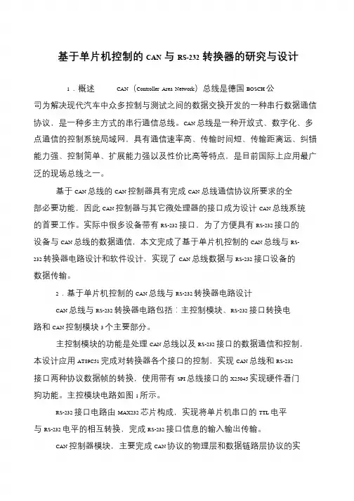
基于单片机控制的CAN与RS-232转换器的研究与设计1.概述CAN(Controller Area Network)总线是德国BOSCH 公司为解决现代汽车中众多控制与测试之间的数据交换开发的一种串行数据通信协议,是一种多主方式的串行通信总线。
CAN 总线是一种开放式、数字化、多点通信的控制系统局域网,具有通信速率高、传输时间短、传输距离远、纠错能力强、控制简单、扩展能力强以及性价比高等特点,是目前国际上应用最广泛的现场总线之一。
基于CAN 总线的CAN 控制器具有完成CAN 总线通信协议所要求的全部必要功能,因此CAN 控制器与其它微处理器的接口成为设计CAN 总线系统的首要工作。
实际中很多设备带有RS-232 接口,为了方便具有RS-232 接口的设备与CAN 总线的数据通信,本文完成了基于单片机控制的CAN 总线与RS- 232 转换器电路设计和软件设计,实现了CAN 总线数据与RS-232 接口设备的数据传输。
2.基于单片机控制的CAN 总线与RS-232 转换器电路设计CAN 总线与RS-232 转换器电路包括:主控制模块、RS-232 接口转换电路和CAN 控制模块3 个主要部分。
主控制模块的功能是处理CAN 总线以及RS-232 接口的数据通信和控制,本设计应用AT89C51 完成对转换器各个接口的控制,实现CAN 总线和RS-232接口两种协议数据帧的转换,使用带有SPI 总线接口的X25045 实现硬件看门狗功能。
主控模块电路如图1 所示。
RS-232 接口电路由MAX232 芯片构成,实现将单片机串口的TTL 电平与RS-232 电平的相互转换,完成RS-232 接口信息的输入输出传输。
CAN 控制器模块,主要完成CAN 协议的物理层和数据链路层协议的实。
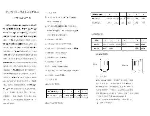
RS485串行口CAN总线转换器CAN485使用手册CAN485RS485串行口/CAN总线转换器:CAN485使用手册一、简介:★功能许多设备上都有RS485接口,利用智能RS485口与CAN总线转换器CAN485,可方便地把带有RS485接口的设备连入CAN总线网络中。
★特点·实现RS485串行口和CAN总线信号的透明转换·LED显示系统通讯状态★技术指标RS232传输速率(bps):1.2K,2.4K,4.8K,9.6K,19.2KRS232接口:DB9插座CAN传输速率(bps):5K,10K,20K,50K,100K,125K,250K,500K,1MCAN接口:2针接线端子CPU:89C51CAN控制器:82C200/SJA1000CAN收发器:82C250RS485收发器:MAX491尺寸:4.0"X2.5"(101mmX66mm)电源功率:+5V@ 100mA 最大200mA温度:0℃~70℃二、使用说明★ RS485接口协议:1个起始位,8个数据位,1个停止位,没有校验位。
★接口定义1.电源接口:5V------------+5VGND-----------地2. RS485接口:TX+ -----------RS485ATX- -----------RS485BRX+ -----------RS422YRX- -----------RS422Z3. CAN接口:H-------------CAN-HL-------------CAN-L★跳线设置1. JMODE:当1,2短接时,为RS485接口;当2,3短接时,为RS422接口;出厂设置为RS485接口。
2. JW:2,3短接。
3. JA:模块节点地址(ID号的高8位):1位至7位代表地址0至127,短路为0,开路为1;第8位保留。
4. JB:第1,2,3位为RS485速率选择,短路为0,开路为1;0--------------1200bps1--------------2400bps2--------------4800bps3--------------9600bps;出厂设置为9600bps4-------------19200bps第4,5,6位为CAN速率选择,短路为0,开路为1;0--------------5Kbps;出厂设置为5Kbps1--------------10Kbps2--------------20Kbps3--------------50Kbps4--------------100Kbps5--------------125Kbps6--------------250Kbps7--------------500Kbps第7位是硬件滤波位,为1时接收总线上的所有信息,为0时只接收ID 号与JA跳线一致节点的信息。
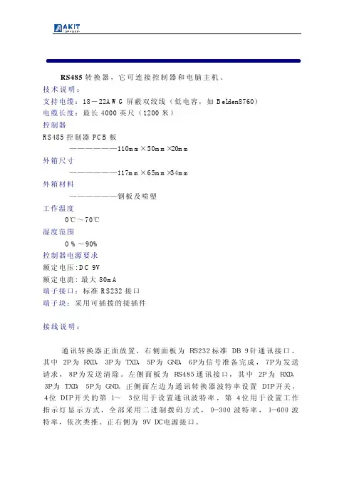
RS485转换器 RS485转换器,它可连接控制器和电脑主机。
技术说明:支持电缆:18-22AWG屏蔽双绞线(低电容,如Belden8760)电缆长度:最长4000英尺(1200米)控制器RS485控制器PCB板——————110mm×50mm×20mm外箱尺寸——————117mm×65mm×34mm外箱材料——————钢板及喷塑工作温度0℃~70℃湿度范围0 %~90%控制器电源要求额定电压: DC 9V额定电流: 最大80mA端子接口:标准RS232接口端子块:采用可插拨的接插件 接线说明:通讯转换器正面放置,右侧面板为RS232标准DB 9针通讯接口,其中2P为RXD,3P为TXD,5P为GND,6P为信号准备完成,7P为发送请求,8P为发送清除。
左侧面板为RS485通讯接口,其中2P为RXD,3P为TXD,5P为GND。
正侧面左边为通讯转换器波特率设置DIP开关, 4位DIP开关的第1~ 3位用于设置通讯波特率,第4位用于设置工作指示灯显示方式,全部采用二进制拨码方式,0-300波特率,1-600波特率,依次类推。
正右侧为9V DC电源接口。
AKT CONVERTOR接线说明 RS232 接线说明右侧面图通讯转换器通讯速率及电源接线说明前侧面图RS-232通讯线接线方法采用9针通讯窜口PC串口(母头)CA-232通讯转换器串口(母头)Pin2-Rxd Pin3-TxdPin3-Txd Pin2-RxdPin5-Gnd Pin5-GndPin4 Pin6Pin6 Pin4Pin7 Pin8Pin8 Pin7RS485接口①③②控制器RS485接口。
User manualrev. 1.5Power supply, Galvanic isolation There are two possibilities how to power the converter. First - the KNX bus is isolated from RS232 bus (default setting). KNX part of converter is powered directly from KNX bus,RS232 part has to be powered from external power supply (through V+ terminal). Second -KNX and RS232 are both powered from KNX bus. There is no need of external power supply in this case. There is a small hole (2,54 mm) on the bottom cover of converter to check current setting. If you can't see red jumpers in the hole, the buses are isolated. In other case they are not isolated one from the other.galvanic isolated busesgalvanic connected buses power supply KNX V+KNX V+6mA2mA / 5-24V8mAunusedJP1, JP2openedclosedGalvanic isolated buses KNX and RS232bottom view without bottom cover (isolated buses)In default settings the buses are isolated. Unused jumpers are placed on holders in middle part of converter.Galvanic connected buses KNX a RS232If you want to power the whole converter only from KNX bus, remove bottom cover and close the JP1 and JP2 with red jumpers. Do non remove the electronics from the box! You could damage small electronic parts!bottom view without bottom cover (galvanic connected buses)The converter is powered from KNX you don't need any external power supply andterminal V+ remains unused.External device communicates with gateway by easy protocol which confirms to the American Standard Code for Information Interchange (ASCII).Type of communication Master – Slave. External device starts communication by command (Master) and gateway answers (Slave)Telegrams for external devices incoming from KNX bus are stored in buffer of gateway. External device reads them one after another (First In First Out). Buffer is able to keep up to 8 telegrams.R S 232R S 232data rate19200 bpscharacter size8 bitsparity evennumber of stop bits1Query or answer containing data<STX>command typedatacheck sum<CR>Answer without data (acknowledge)Command accepted:<ACK>Command refused:<NAK><STX>start of message – 2 (0x02)<CR>end of message – 13 (0x0D)<ACK>confirmation of command – 6 (0x06)<NAK>rejection of command – 21 (0x15)<NAK> is answered in case, that given address is not set in gateway, or the length of date (format) is wrong.All the other bytes (command type, data, check sum) are numbers in hex format (0x00 – 0xFF) in ASCII coding – into two bytes in range …0“ – …9“ (0x30 – 0x39) or …A“ – …F“ (0x41 – 0x46).Example: Command type 0x04 (query received telegram from KNX) is written in two bytes …0“ – 0x30 and …4“ – 0x34.The whole query command for received telegram from KNX:<STX> 0x04 0xFB <CR> is transmitted in 6 bytes (1B <STX>, 2B command, 2Bcheck sum and 1B <CR>).The whole message on RS232 will look as follows: 0x02, 0x30, 0x34, 0x46, 0x42, 0x0D.command type description0x01 query gateway firmware version0x04 query received telegram from KNX bus0x0B store data in group address on KNX0x0C query data from group address on KNXConfiguration commands for setting of converter KNX232command type description0x40load the list of listened addresses from converter KNX2320x41store the list of listened addresses from converter KNX232Check sum is calculated according to the following rule:8-bit addition of all bytes of message except for bytes STX and CR and negation the result bit by bit.Example: (query data from group address 1/1/1)STX 0x0C 0x09 0x01 0xE9 CR0x0C + 0x09 + 0x01 = 0x16Negation of the byte 0x16 results in the check sum 0xE9Query:command type0x01data not usedAnswercommand type0x81data gateway firmware version – 2 bytesVersion is in format x.y, first byte represents x and second byte y. ExampleCommand<STX> 0x01 0xFE <CR>Answer<STX> 0x81 0x01 0x15 0x68 <CR>Firmware version is 1.21 (0x01.0x15)Query:command type0x04data not usedAnswercommand type0xFCdata group address – 2 bytesdata – n bytesor<ACK>No new data have been received from KNX bus. ExampleCommand<STX> 0x04 0xFB <CR>Answer<STX> 0xFC 0x09 0x01 0x07 0xF2 <CR>New received data 0x07 from address 1/1/1.or<ACK>No new data have been received from KNX busStore:command type0x0Bdata group address – 2 bytestransmit priority – 1 byte (0x0C or 0x04)data – n bytesAnswer<ACK>or<NAK>ExampleCommand<STX> 0x0B 0x09 0x01 0x0C 0x07 0xD7 <CR> Answer<ACK>Data 0x07 were stored in group address 1/1/1. Allowed transmit priority: 0x0C for low priority level0x04 for high priority level.Query:command type0x0Cdata group address – 2 bytesAnswer<ACK>or NAK>ExampleCommand<STX> 0x0C 0x09 0x01 0xE9 <CR>Answer<ACK>Query transmitted to group address 1/1/1.The command configures the converter KNX232. If the setting of converter is done by Configate software the configuration command will not be used.Store setting into the converter:command type0x41data position of item in converter memory (2 bytes)0-249 – list of listened group addresses65535 (0xFFFF) physical address of converterKNX address (2 bytes)group or physical address0xFFFF means, in case of group address, that thisposition will not be used (deleting of item)Data typegroup address format (1=EIS1 and so on)In case of physical address set to 0.Answercommand type0xC1data position of item in converter memory (2 bytes)0-249 – list of listened group addresses65535 (0xFFFF) physical address of converterKNX address (2 bytes)group or physical address0xFFFF means, in case of group address, that this itemis not used.Data typegroup address format (1=EIS1 and so on)ExampleCommand<STX> 0x41 0x00 0x00 0x09 0x03 0x01 0xB1 <CR>Save group address 1/1/3 (0x09,0x03) with format EIS1 (0x01) intofirst position in memory (0x00,0x00).Answer<STX> 0xC1 0x00 0x00 0x09 0x03 0x01 0x31 <CR>Group address 1/1/3 (0x09,0x03) with format EIS1 (0x01) is saved infirst position in memory (0x00,0x00).The command upload the list of listened addresses from the converter KNX232. If the setting of converter is done by Configate software the configuration command will not be used.Uploadcommand type0x40data position of item in memory of converter KNX232 (2 bytes)0-249 – list of listened group addresses65535 (0xFFFF) physical address of converterAnswercommand type0xC0data position of item in memory of converter KNX232 (2 bytes)0-249 – list of listened group addresses65535 (0xFFFF) physical address of converterKNX address (2 bytes)group or physical address0xFFFF means in case of group address, that this item isnot used.Data typegroup address format (1=EIS1 and so on)ExampleCommand<STX> 0x40 0x00 0x00 0xE9 <CR>Upload the group address from the first position of memory ofconverterAnswer<STX> 0xC0 0x00 0x00 0x09 0x03 0x01 0x32 <CR>Group address 1/1/3 (0x09,0x03) with format EIS1 (0x01) is saved infirst position of memory (0x00,0x00).Easy configuration software Configate.exe runs under OS Windows 2000 and later. It serves as a tool for setting group and physical addresses of actors and sensors connected to KNX bus. Each group address to be used by external device must be programmed in the gateway. Configate can be downloaded for free from: http://www.foxtron. e uA tree with group addresses can be created by following buttons:New Address - inserts new item with address area, line or device. The item isinserted as subnode under selected node.Remove - deletes selected item, including all subnodes.Edit Name - using this button the name of selected item can be changed.A format of telegrams (EIS) of selected device items can be chosen from the list in EIS menu.Created address tree can be saved by command Save in menu File. Default extension of saved files is.cg.Saved address tree can be load by command File->Open.By command File -> New will be current tree deleted and new one created.Created address tree can be stored into the gateway KNX232 or read from it by buttons Send and Receive . Appropriate serial port with gateway can be selected in Port menu. Physical address can be changed by button Change. The software will ask for all threeparts of address one after another.RS232 terminal description V+5-24V – power supply of RS232 part in case of galvanic isolated buses Rx RS232 received data Tx RS232 transmitted dataGNDRS232 signal ground (in case of galvanic isolation – ground for supply of RS232 part)Terminal V+ serves for power supply of RS232 part of the gateway if KNX and RS232 are isolated (see part “power supply, galvanic isolation”).If the buses are not isolated, the whole gateway is supplied from KNX bus and terminal V+ is not used. Wire preparation:0,6 – 0,8mm 2 0,08 – 1,5mm 2KNX/EIBKNXV+Rx Tx GNDtel: +420 274 772 527e-mail:***************web: www.foxtron.eu4590105817。
GCAN-202工业级以太网-CAN转换器用户手册文档版本:V3.52 (2017/09/30)修订历史目录1. 功能简介 (4)1.1 功能概述 (4)1.2 性能特点 (4)1.3 典型应用 (5)2. 设备安装 (6)2.1 安装固定 (6)2.2软件安装 (7)2.3 与PC连接 (7)2.4 与CAN总线连接 (7)3. 设备使用 (8)3.1 与PC连接进行配置 (8)3.2 与以太网连接 (9)3.3 与CAN连接 (11)3.4 CAN总线终端电阻 (12)3.5 系统状态指示灯 (12)4. CANet Config软件使用 (14)4.1 恢复出厂设置 (14)4.2 GCAN-202连接 (14)4.3 配置通讯基本信息 (15)4.4 配置完成 (17)4.5 保存/加载配置文件 (18)4.6 升级CANet固件内核(此功能请在指导下使用) (18)5. CANet简易测试软件使用 (20)6. 网络调试助手使用方法 (21)6.1 调试前准备工作 (21)6.2 TCP Server模式通信测试 (22)6.3 TCP Client模式通信测试 (23)6.4 UDP模式通信测试 (24)6.5 CAN口状态的TCP通知数据格式说明 (25)7.GCAN-202在线修改波特率功能 (26)7.1 功能说明 (26)7.2 格式说明 (26)7.3 发送举例 (26)8. 二次开发 (27)9. 技术规格 (28)10. 常见问题 (29)附录A:CAN2.0B协议帧格式 (30)附录B:GCAN-202(CANet)数据流定义 (32)1. 功能简介1.1 功能概述广成科技GCAN-202(CANET-II)是集成2路CAN接口、1路以太网接口的高性能型CAN-bus总线通讯接口卡。
采用GCAN-202高性能CAN接口卡,用户可以轻松完成CAN-bus 网络和以太网网络的互连互通,进一步拓展CAN-bus 网络的范围。
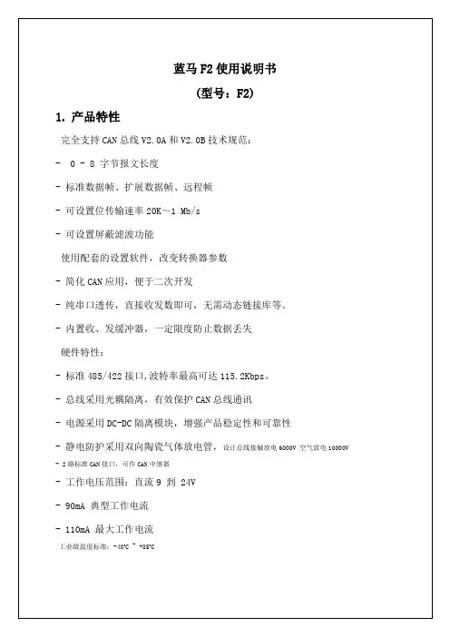
CAN总线智能网关中继器用户手册 V1.0一、 产品概述CAN总线智能网关中继器是高性能CAN总线隔离中继网关,可增加CAN总线通讯距离,具备网关过滤功能,实现数据隔离,降低CAN总线负荷。
本设备可匹配不同通讯波特率CAN总线。
二、 产品特点同时支持CAN2.0A,CAN2.0B协议波特率10Kbps--1MbpsUSB接口配置产品参数,无需安装任何驱动2路完全电器隔离CAN通道每路CAN可独立配置通讯波特率每路CAN可独立配置验收过滤条件内置CAN总线120欧姆终端电阻,可断开自行配置工作电源:DC8-30V支持标准DIN导轨安装三、 产品使用3.1 产品展示3.2 接口定义端口标识功能 备注 CAN2-H CAN2高 CAN2-LCAN2低 Res2+Res2-CAN2自定义终端电阻 出厂时终端电阻已内部接入GND工作电源输入负 VCC工作电源输入正 DC8-30V Res1-Res1+CAN2自定义终端电阻 出厂时终端电阻已内部接入 CAN1-LCAN1低 CAN1-H CAN1高 CAN 总线终端电阻如需去除或自定义,打开外壳去除跳线,即可去除或外接自定义终端电阻。
CAN1跳线CAN2跳线3.3 USB 端口USB 接口为方形USB 口,连接电脑USB 口配置参数,模块即可上电,无需外接电源。
连接电脑时无需安装任何驱动。
3.3 LED 指示RUN 闪烁:模块运行正常 非闪烁:模块异常CAN1 闪烁:有CAN 数据通讯 灭:无数据通讯CAN2 闪烁:有CAN 数据通讯 灭:无数据通讯3.3 配置工具使用USB 线将设备连接到电脑USB 端口后,系统将自动为设备安装USB 驱动。
运行配置软件对设备CAN 波特率及过滤条件设置。
配置工具中左右分别为CAN1与CAN2配置,功能完全相同,可完全独立配置。
可选择预置的波特率,当勾选自定义波特率时可以手动输入参数调节。
CAN网关部分则为针对数据的过滤条件:按ID匹配转发和按ID范围禁止转发。
RS485/232转CAN测试说明下图为实体板卡图:程序在我的电脑/本地磁盘E/can To 232 485配置软件在我的电脑/本地磁盘E/can To 232 485/SoftWare/Config/bin/Debug1.打开A.jflash,选择下载文件,连接下载器和板卡,点击Target-Manual Programming-Erase Chip(或者快捷键F4),成功则点击Target-Manual Programming-Program & Verify(或者快捷键F6),成功选择Target-Manual Programming-Secure Chip成功即下载完成。
2.找到与板卡相同,带有连线和端子的那块测试板卡,然后将测试板卡和要测试的板卡都分别连接上USB转串口,上电。
3.先测试232转CAN,先将测试板用软件配置为232,选择CAN网关,选择好相对应的串口号,转换模式为透明传输,把CAN过滤配置四个勾给勾上,要将一个小端子接上测试板,然后点配置,收到配置成功即配置完成。
4.拔掉小端子,两个板卡相连接,上电,打开两个串口调试助手,设置波特率9600,打开两个串口,两个分别发送任意字符(HEX收发,否则全是乱码,不容易看),在另一端能收到内容即232和CAN通道正常。
5.接着测试485转CAN,先将测试板用软件配置成485,选择CAN网关,选择好相对应的串口号,转换模式为Modbus转换,把CAN过滤配置四个勾给勾上,要记得将小端子接上测试板,然后点配置,收到配置成功即配置完成。
6.拔掉测试板上的小端子,装在被测试板上,两个板卡相连接,软件配置如同第5点,配置完成后断电,再上电,测试板4号灯亮(闪烁),被测试板3号灯亮(闪烁)即485通道没有问题。
(PS:配置软件:透明传输为232通道;modbus转换为485通道)下图为测试板与被测试板相连接图:下图为产品相关测试软件与步骤:。
GY850X CAN232MB/CAN485MB/CAN422MBCAN总线协议转换器型号产品名称描述CAN总线协议转换器 CAN总线转RS232GY8502 CAN232MBCAN总线协议转换器 CAN总线转RS485GY8503 CAN485MBCAN总线协议转换器 CAN总线转RS422GY8504 CAN422MB说明书时间硬件版本软件版本V1.0 2006年11月V1.0 V1.0 Beta发布V2.2 2008年4月V2.1 V2.1 CAN232MB,CAN485MB手册整理V2.3 2008年5月 V2.2 V2.2 说明书整理,增加CAN422MB目录目 录 (2)第一章 产品简介 (4)1.1 概述 (4)1.2 性能与技术指标 (4)1.3 典型应用 (5)1.4 产品销售清单 (6)1.5 技术支持与服务 (6)第二章 硬件描述与使用方法 (7)2.1 产品外观 (7)2.2 CAN总线接口定义 (7)2.3 DB9端接口定义 (8)2.4 指示灯定义 (8)2.5 CAN总线连接 (8)第三章 配置说明 (9)3.1 配置方法 (9)3.2 软件说明 (9)3.2.1 配置基本参数 (10)3.2.2 配置串口参数 (12)3.2.3 配置CAN接口参数 (12)3.2.4 举例介绍验收滤波的设置 (14)3.2.5 软件下方按钮说明 (16)第四章 应用说明 (16)4.1 模式1 透明转换模式 (17)4.1.1 串行帧转CAN 报文 (17)4.1.2 CAN报文转串行帧 (18)4.2 模式2 透明带ID标识转换 (18)4.2.1 串行帧转CAN 报文 (18)4.2.2 CAN报文转串行帧 (20)4.3 模式4 透明带ID标识转换2 (21)4.4 应用注意事项 (21)4.5 转换器测试 (21)4.5.1 电源测试 (21)4.5.2 配置测试 (22)4.5.3 通讯测试 (22)第五章 附录 (23)5.1 CAN2.0B 协议帧格式 (23)5.1.1 CAN2.0B 标准帧 (23)5.1.2 CAN2.0B 扩展帧 (23)5.2 SJA1000 标准波特率 (24)5.3 CAN 报文滤波器设置 (25)声明 (29)第一章产品简介1.1 概述GY8502 CAN232MB CAN总线协议转换器是用于CAN-bus 现场总线和RS232总线之间数据交换的智能型协议转换器。
GY8503 CAN485MB CAN总线协议转换器是用于CAN-bus 现场总线和RS485总线之间数据交换的智能型协议转换器。
GY8504 CAN422MB CAN总线协议转换器是用于CAN-bus 现场总线和RS422总线之间数据交换的智能型协议转换器。
GY850X CAN总线协议转换器可以快速将RS232/RS485/RS422通讯设备连接到CAN-bus 现场总线。
该协议转换器集成有1个RS232/RS485/RS422串行通道、1个CAN-bus 通道,可以很方便地嵌入到使用RS232/RS485/RS422 接口进行通讯的节点中,在不需改变原有硬件结构的前提下使设备获得CAN-bus 通讯接口,实现RS232/RS485/ RS422设备和CAN-bus 网络之间的连接、数据通讯。
GY850X CAN总线协议转换器为用户的使用提供了足够的灵活性,用户可以根据实际需要设置CAN总线接口和RS422接口的参数。
通讯参数由上位机软件配置,能使用户快速进入高效率的CAN-bus 通讯应用。
GY850X CAN总线协议转换器提供两种数据转换方式:“透明转换”、“透明带ID标识转换”。
“透明转换”适用于串行数据流的完全转换,“透明带ID标识转换”适用于用户自定义协议的串行数据转换,用户可根据实际应用的特点选择合适的数据转换方式。
转换器采用贴片安装工艺,CAN总线电路采用独立的DCDC电源模块,进行光电隔离,与控制电路完全电气隔离,使GY850X转换器具有很强的抗干扰能力,大大提高了系统在恶劣环境中使用的可靠性。
GY850X智能协议转换器不仅适用于采用基本CAN总线协议的产品,也满足基于高层协议如DeviceNet、CANopen 等CAN-bus总线产品的开发。
1.2 性能与技术指标● 功能兼容ZLG-CAN232MB/CAN485MB协议转换器● 实现CAN总线与RS232/RS485 的双向数据通讯,CAN总线发送和接收;● 支持CAN2.0A 和CAN2.0B 协议,支持标准帧和扩展模式;● 支持数据帧,远程帧格式;● 支持CAN总线自发送自接收工作模式。
● 支持用户软件配置自定义的CAN总线通讯波特率:5K-1000Kbps;● 3线式RS232,或2线式RS485,或4线式RS422 通讯接口,通讯速率在2400~115200bps之间可设定;(注:RS485,RS422接口速率最大为57600)● 提供两种数据转换模式:透明转换、透明带ID标识转换;● 大容量的环形串行缓冲区,可以接受的一个串口数据帧长度最大可达480个字节。
● CAN总线接口采用光电隔离、DC-DC电源隔离(1000V);● 最高帧流量:300 帧/秒;● 工作电源:+7V~+40V DC;可根据要求提供5V接口。
● 工作温度:-40 ℃ ~ +85℃;● 支持标准DIN 导轨安装;● 产品尺寸:100mm*70mm*25mm(不计算导轨安装架高度)。
1.3 典型应用● 设备与设备间采用CAN总线通信● CAN网络取代RS232/RS485/RS422网络● 扩展标准RS232/RS485/RS422网络通讯长度;● 煤矿远程通讯● PLC 设备联网● 现有RS232/RS485/RS422设备连接CAN-bus 网络● 扩展标准RS232/RS485/RS422 网络通讯长度● PLC 设备连接CAN总线网络通讯转换● CAN总线与串行总线之间的网关网桥● 工业现场网络数据监控● CAN 教学应用远程通讯● CAN 工业自动化控制系统● 慢速CAN 网络数据采集数据分析● 智能楼宇控制● 数据广播系统等CAN总线应用系统1.4 产品销售清单1)GY850X CAN总线协议转换器。
2)DB9串口线缆一根。
(仅GY8502)3)光盘1张。
(设备配置软件CANConfig,用户手册,CAN总线相关资料等);1.5 技术支持与服务货到10日内无条件退货;一年年内免费维修或更换;终身维修服务。
技术支持信息请查阅本公司网站第二章硬件描述与使用方法2.1 产品外观CAN232MB/CAN485MB/CAN422MB 转换器具有两路用户接口。
一路是CAN-bus接口,一路是RS232/RS485/RS422串行接口。
其接口引脚定义如下。
2.2 CAN总线接口定义引脚信号定义说明电源正(7-40V)1 Vin2 0V电源地(0V)配置引脚3 CFG电源地4 GNDRS485信号正端(仅CAN485MB)5 A+RS485信号负端(仅CAN485MB)6 B-内部120电阻正端7 RES+内部120电阻负端8 RES-CANL信号9 CANLCANH信号10 CANH引脚1标示“Vin”接外部+7V~+40V直流电源,引脚2标示“0V”是接外部电源地。
引脚3标示“CFG”是转换器的配置引脚。
该脚悬空时上电后转换器进入正常转换模式;若该引脚和引脚4标示“GND”相连后,转换器上电即进入配置模式。
引脚7标示“Res-”和引脚8标示“Res+”如果被用导线短接,则CAN网络的终端电阻120欧姆被接入(卡内置)。
当CAN232MB/CAN485MB转换器作为CAN-bus网络终端时,两引脚间需要短接(即使用内部的120欧);否则让其悬空(不使用内部的120欧)。
2.3 DB9端接口定义引脚信号定义说明1 RS485_A(RS422_RX+)RS485的正端,或者RS422的接收正端2 RS232_RXD RS232数据输入,接收3 RS232_TXD RS232数据输出,发送4 RS422_TX+ RS422的发送正端5 GND RS232信号地6 RS485_B(RS422_RX-)RS485的负端,或者RS422的接收负端7 NULL8 RS422_TX- RS422的发送负端9 NULL2.4 指示灯定义转换器表面的红色LED-Power灯指示电源;正常上电后POWER指示灯立即点亮。
当转换器通电自检完成后,COM LED和CAN LED均点亮。
当串口侧有数据传输时,COM LED闪烁,无数据时长亮。
当CAN侧有数据传输时,CAN LED闪烁,无数据时长亮;当转换器通过CFG=0进入设置模式时,只有COM LED 亮。
2.5 CAN总线连接图2.5 CAN总线设备连接示意图转换器作为终端设备时,用户可以在C AN232MB/ CAN485MB 转换器的CAN接口,引脚7 即“Res+”、引脚8即“Res+”用户可以用导线短接,使内部120Ω的终端电阻使能。
第三章配置说明由于CAN-bus 总线、串口的通讯参数较多,GY850X转换器开放了大部分的参数,让用户可以自行设定,以切合实际应用场合的需要。
可以配置转换器的转换方式,串口参数和CAN-bus 参数等。
参数的配置是通过专门的配置软件完成,无需硬件跳线配置。
在正常使用之前,需要预先配置好转换器的转换参数;如果没有进行配置,那么,GY850X 转换器执行的是上一次配置成功的参数(如果一次都没有配置,那么转换器执行默认的配置参数)。
GY850X转换器可以直接和PC串口连接,进行参数配置。
GY8503 CAN485MB需要客户自行准备RS232-485的转换器,连接CAN485MB的485接口即可通过PC进行配置。
RS232-485转换器需要能支持9600bps的速率。
GY8504 CAN422MB需要客户自行准备RS232-422的转换器,连接CAN422MB的422接口即可通过PC进行配置。
RS232-422转换器需要能支持9600bps的速率。
3.1 配置方法为了使转换器进入配置模式,用户只需要将CAN 接口侧的引脚3 标示“CFG”和引脚4 标示“GND”用导线短接。
“CFG”接地后,转换器上电后进入“配置”模式;“CFG”脚悬空时,转换器上电后会进入“正常工作”模式。
进入配置步骤如下:1. 将转换器的CFG 和GND 用导线连通,然后上电,检查是否CAN_LED是否闪烁一下然后熄灭。
2. 用串口线连接转换器和计算机。
3. 打开上位机配置软件CANConfig,打开串口,进行参数设定。
3.2 软件说明图 3.1 配置软件界面GY850X 转换器的配置软件名称为“CanConfig.exe”。