Document splitting
- 格式:docx
- 大小:492.42 KB
- 文档页数:9
SAP 凭证分割–配置相关SAP ECC 交付时系统中已经预配置了凭证分割规则,项目实施过程中可以最少化的去做“客户化”的配置,而且SAP 也推荐使用标准功能。
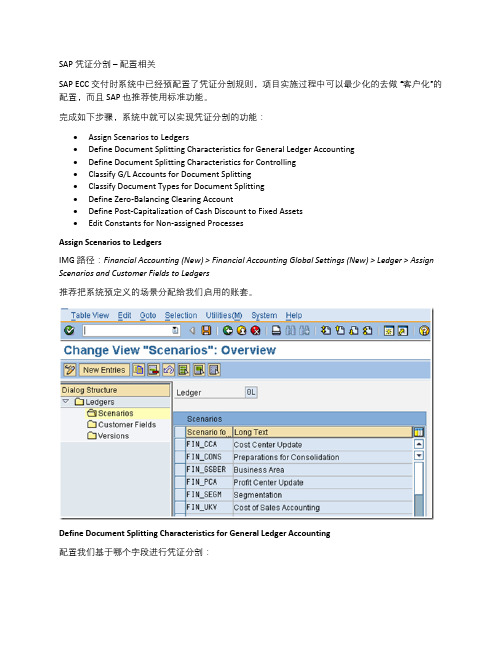
完成如下步骤,系统中就可以实现凭证分割的功能:∙Assign Scenarios to Ledgers∙Define Document Splitting Characteristics for General Ledger Accounting∙Define Document Splitting Characteristics for Controlling∙Classify G/L Accounts for Document Splitting∙Classify Document Types for Document Splitting∙Define Zero-Balancing Clearing Account∙Define Post-Capitalization of Cash Discount to Fixed Assets∙Edit Constants for Non-assigned ProcessesAssignScenariostoLedgersIMG 路径:Financial Accounting (New) > Financial Accounting Global Settings (New) > Ledger > Assign Scenarios and Customer Fields to Ledgers推荐把系统预定义的场景分配给我们启用的账套。
Define Document Splitting Characteristics for General Ledger Accounting配置我们基于哪个字段进行凭证分割:勾选零余额,系统会利用我们定义的中间科目来确保分割之后各个利润中心下资产负债表的平衡。

【关键字】企业企业内部控制审计底稿模板篇一:内控审计底稿模板2-1 了解五个方面*******会计师事务所有限公司二、风险评估工作底稿被审计单位名称:所属会计师事务所:项目负责人:日期:*******会计师事务所有限公司了解被审计单位及其环境(不包括内部控制)所属会计师事务所:一、审计目标从以下方面了解被审计单位及其环境,识别和评估财务报表层次和认定层次的重大错报风险(无论该错报由于舞弊或错误导致),从而为设计和实施针对评估的重大错报风险采取的应对措施提供根底:1.行业状况、法律环境与监管环境以及其他外部因素,包括适用的财务报告编制根底;2.被审计单位的性质,包括经营活动、所有权和治理结构、正在实施和计划实施的投资(包括对特殊目的实体的投资)的类型、组织结构和筹资方式;3.被审计单位对会计政策的选择和运用,包括变更会计政策的原因。
注册会计师应当根据被审计单位的经营活动,评价会计政策是否适当,并与适用的财务报告编制根底、相关行业使用的会计政策保持一致;4.被审计单位的目标、战略以及可能导致重大错报风险的相关经营风险;5.被审计单位财务业绩的衡量和评价;二、行业状况、法律环境与监管环境以及其他外部因素,包括适用的财务报告编制根底;(一)实施的风险评估程序1.此处应详细记录了解被审计单位及其环境时实施的风险评估程序,包括询问、观察、检查和分析程序。
记录的内容应包括实施审计程序的性质、时间和范围。
2 .此处评估出的风险,最终应汇总至风险评估结果汇总表。
(二)了解的内容和评估出的风险1.行业状况(1)所在行业的市场供求与竞争2(3)产品生产技术的变化(4)能源供应与成本(5)行业的关键指标和统计数据(1)适用的财务报告编制根底和行业特定惯例(3)对经营活动产生重大影响的法律法规及监管活动(4)税收政策(关于企业所得税和其他税种的政策)(5)对开展业务产生重大影响的政府政策,包括货币(包括外汇管制)、财政、财政刺激措施(如政府援助项目)、关税或贸易限制政策(6)与被审计单位所处行业和所从事经营活动相关的环保要求4.其他外部因素(1)宏观经济的景气度(2)利率和资金供求状况(3)通货膨胀水平及币值变动(4)国际经济环境和汇率变动三、被审计单位的性质,包括经营活动、所有权和治理结构、正在实施和计划实施的投资(包括对特殊目的实体的投资)的类型、组织结构和筹资方式。

--Starter ProfessionalBusiness label design and printing Easy-to-use design tools and basic printing management••Dynamic business printing Data entry forms, Intelligent Templates™, database connectivity, encoding and manual printing•Unlimited users Enable multiple users to print labels from any networked PC••Number of printers BarTender is licensed by printer Up to 3printers1+ printers----Starter ProfessionalStandard Maintenance and Support Upgrade to the latest BarTender version free, and get live technical support by phone and chatduring business hours with a guaranteed 24 hour response time. Access to online resources, plustechnical supportIncludes1 yearIncludes1 year----Starter ProfessionalEasy WYSIWYG template design Design tools make it easy to create and print professional labels and documents••Global support Intuitive, easy-to-use user interface, translated to more than 20 languages••Comprehensive help system A complete how-to library, accessible both through BarTender and on the web••Quick start A collection of configurable, industry-focused, ready-to-use BarTender templates••New Document Wizard An easy-to-follow wizard that ensures proper document settings for quality and printingperformance••Fonts Versatile support for OpenType, TrueType, Symbol Font characters and native printer-basedfonts••Text formatting Familiar, MS Word-like tools for creating and formating text••Transformed text Add flair to your text objects with a variety of effects, such as fading, inflating, slanting, and more••Shapes and lines Choose from over 50 shapes and 100 line style combinations••Dynamic text and object wrapping Create dynamic text that wraps inside and around shapes, objects, document borders and more••Unmatched barcode support Choose from over 100 1D and 2D symbologies based on over a dozen standards••Human readable barcode Highly configurable human readable text and character formatting options••GS1 Application Identifier Data Source Wizard Construct GS1-compliant barcodes in seconds••Graphics and images Import more than 70 graphic formats, including AI, PNG, JPG, BMP, TIF, EPS and GIF••Symbols Choose from a wide variety of included symbols and industry-based symbol fonts••Tables and grids Create tables and grids to organize text, barcodes, images and other objects••White-on-black printing Switch objects from black-on-white to white-on-black printing with a single click••Front and back template design Create two-sided, “duplex” printing with separate designs for the front and back of yourtemplate••Amazon Transparency support Create Amazon Transparency product serialization codes that help identify individual units andproactively prevent counterfeits••Embedded revision logging Capture a revision trail directly in the document — when it was saved, who saved it and includeadditional comments•Full color support Design commercial quality labels using PANTONE and data-sourced colors•----Starter Professional Suppression Ignore the content of a data source under certain conditions••Label templates Design and automation tools that leverage data to reduce the number of label files you manage•Conditional printing Create data-driven automation rules that specify when different objects, layers or templates inyour document will visibly print or become hidden•Template selector Conditionally print one specific template when multiple templates are available in a document•Layers Template objects may be stacked, hidden and reordered when created on uniquely identifiablelayers•Automatic face detection and cropping Automated image capture creates perfectly cropped photos for ID badges and card printing•Scriptable object properties Modify the look and feel of template objects by using Visual Basic (VB) scripts•----Starter Professional Date and time Dynamically source dates and times from Windows or clock-enabled printers••Data validation and processing Specify data validation rules and automatically correct data or issue warnings••Concatenate data Create text and barcode objects that combine information from multiple data sources••Basic database connectivity Import variable data from Excel or a RFC 4180 standard CSV files into your template••Simple serialization Increase or decrease your serial string data by increments of one (1)••Named database connections Name commonly used database connections to quickly add them to new document designs••Database filters Print select database records using convenient query and filter options#•Database sourced tables Easily create tables using data from a database or external file#•Dynamic data preview See how your document handles real dynamic data during the design process#•Dynamic graphics and images Automatically source images for printing based on selected database records or queries#•Embedded database tables Create your own database tables that travel with your BarTender document designs•Enhanced database connectivity Connect document designs to over 20 data sources such as SAP, Oracle, MS SQL, Azure SQL, XML,Excel, text files and more to print dynamically•Advanced serialization Create serial numbers that support alphanumeric, hexadecimal and custom sequencing patterns•Create a database Build your own database from scratch using intuitive tools included with BarTender•Write back to databases Write back to SQL-based databases to keep track of printed records, serial numbers and muchmore•Visual Basic (VB) scripting Create scripts for custom data processing•Global database field Centralize a data field and share it between BarTender documents•----Starter Professional Database record selection Select or query the correct database records at print time using helpful form controls•Powerful form controls Make data input and selection easy by leveraging over 15 highly configurable form controls•Keyboard and mouse input Use keyboard and mouse commands to select or enter data into forms at print time•Scanner input Use a barcode scanner to input information to data entry forms at print time•Weighing scale input Populate the weight of an item at print time by connecting your weighing scale to BarTender•Image capture Capture images at print time for ID cards or event badge printing•Data validation Reduce user input errors by introducing data validation and error checking•----Starter Professional Drivers by Seagull™More than 7,000 printers and output devices supported to enable high-performance printing••Print optimizations Improve print speed by taking full advantage of printer-based features such as serialization,barcodes, real-time clock, static data and graphic caching••Windows printer drivers Print to any printer that has a Windows-based driver••Printer configuration and diagnostics Perform printer management functions in BarTender, bypassing the printer front panel••On-demand and batch printing Print labels and documents on-demand or batch together using one or more BarTendertemplates••Print preview Review your dynamic print jobs before printing••Image exporting Export entire template images or specific objects in 35+ formats••RFID, smartcard and magnetic stripe encoding Encode RFID tags, smartcards and magnetic stripe cards as easily as adding barcodes to yourtemplate design•Native PDF generation Generate PDFs without installing third-party PDF drivers•----Starter Professional Status monitoring Reports information back to Windows regarding printer/print job status and error conditions••Email alerts Automatically notify IT managers or other operational team members if labeling problems occur••----# Basic databases only (Excel or RFC 4180 standard CSV file)BarTender Release 11.3 R5 and later versions。

Document类型知识⼤全Document类型1.⽂档的⼦节点Document类型可以表⽰HTML页⾯或者其他基于XML的⽂档。
不过,最常见的应⽤还是作为HTMLDocument实例的document对象。
通过这个⽂档对象,不仅可以取得与页⾯有关的信息,⽽且还能操作页⾯的外观及其底层结构。
虽然DOM标准规定Document节点的⼦节点可以是DocumentType、Element、ProcessingInstruction或Comment,但还有两个内置的访问其⼦节点的快捷⽅式。
第⼀个就是documentElement属性,该属性始终指向HTML页⾯中的<html>元素。
另⼀个就是通过childNodes列表访问⽂档元素,但通过documentElement属性则能更快捷、更直接地访问该元素。
作为HTMLDocument的实例,document对象还有⼀个body属性,直接指向<body>元素。
因为开发⼈员经常要使⽤这个元素,所以document.body在JavaScript代码中出现的频率⾮常⾼,2.查找元素说到最常见的DOM应⽤,恐怕就要数取得特定的某个或某组元素的引⽤,然后再执⾏⼀些操作了。
取得元素的操作可以使⽤document对象的⼏个⽅法来完成。
其中,Document类型为此提供了两个⽅法:getElementById()和getElementsByTagName()。
第⼀个⽅法,getElementById(),接收⼀个参数:要取得的元素的ID。
如果找到相应的元素则返回该元素,如果不存在带有相应ID的元素,则返回null。
注意,这⾥的ID必须与页⾯中元素的id特性(attribute)严格匹配,包括⼤⼩写。
IE8及较低版本不区分ID的⼤⼩写,因此"myDiv"和"mydiv"会被当作相同的元素ID。
如果页⾯中多个元素的ID值相同,getElementById()只返回⽂档中第⼀次出现的元素。

SAP移动类型详细说明SAP移动类型详细说明101 Goods receipt for purchase order or order 101有关采购订单或生产订单的收货If the purchase order or order has not been assigned to an account, a stock type (unr estricted-use stock, stock in quality inspection, blocked stock) can be entered during goods receipt.如果采购订单或订单没有指定科目,其库存类型(非限制使用库存、质量检验库存、冻结库存)可以在收货的时候输入。
If the purchase order or order has been assigned to an account, the goods receipt is not posted to the warehouse, but to consumption.如果采购订单或订单已经存在科目分配,收货没有过帐到仓库库存中,而是过帐到消耗中(PS.如成本中心、固定资产、办公用品等)。
In the case of non-valuated materials, the goods receipt is posted to the warehouse, although the purchase order has not been assigned to an account.对于无评估物料的情况,收货时也会过帐到仓库中,尽管采购订单中没有分配科目。
Possible special stock indicators:相关的特殊库存标识:• K Goods receipt for purchase order to consignment stockK有关寄售库存采购订单的收货• O Goods receipt for purchase order to stock of material provided to vendorO有关委外加工库存采购订单的收货(分包)• E GR for purchase order or order to sales order stockE有关销售订单库存的收货• Q GR for purchase order or order to project stock.Q有关项目库存采购订单的收货Goods receipt for subcontract order: at goods receipt, the consumption of the compon ents is posted at the same time (see movement type543)有关分包订单的收货:在收货时,组件的消耗过账也会同时进行(参见移动类型543)(PS.委外加工后返回的物料,原先在库存中的状态为:分包,在101收货的同时,系统会自动作543的转储动作将物料从分包库存转储到非限制自有库存中)。

Data sheetHP LaserJet MFP M232-M237 Printer seriesSuper productive. Super compact – with reliable wireless.A high-productivity MFP with the fastest two-sided printing in its class, an automatic feeder, and the time-saving HP Smart app. Count on peace of mind from more reliable connections, and a worry-freeexperience with simplified setup.This printer uses dynamic security, which maybe updated periodically by firmware updates.The printer is intended to be used solely withcartridges using an original HP chip. Cartridgesusing a non‐HP chip may not function or maycease to function. More at: Learn more at:/learn/dsWork fast. Work smart.Speed through multipage documents with the fastest in-class two-sided printing speed.You can fit this LaserJet almost anywhere – it’s that small and compact. Get projectsdone quickly with a printer that fits almost anywhere.Get better range and faster, more reliable connections using dual-band Wi-Fi™ with self-reset.Easily handle large print jobs, and save time with automatic scanning and copying.Breeze through scan and copy tasks, using the automatic document feeder.Stay productive from anywhereGet high-quality scanning. Share to Dropbox, Google Drive, email, or the cloud – fromvirtually anywhere – with HP Smart app.Quickly access and print documents and images on your smartphone, from Dropbox andGoogle Drive, using HP Smart app.With HP Smart app, you can stay connected to your printer from virtually anywhere. Getnotifications when printing, scanning, or copying from your smartphone.Easy to set up, easy to useGet started fast with easy setup that guides you, step by step. Simply download the HPSmart app, connect to a network, and share your printer across all your devices.Easily manage tasks with smart-guided buttons for an intuitive experience – buttonsappear only when needed.Help make a positive impact on the environmentThis HP LaserJet meets Eco Label requirements, including ENERGY STAR® and BLUEANGEL.Help save energy with a LaserJet that uses up to 20% less energy than previous model.Help save energy with HP Auto-On/Auto-Off Technology – intelligence that can turn yourprinter on when you need it and off when you don’t.123,45,215,22333336Product walkaroundHP LaserJet MFP M232–M237 series (sdn/sdw)1. 40 sheet auto document feeder2. HP Smart app3. ID copy4. USB, Ethernet, dual-band Wi-Fi with self reset5. 100 sheet output tray6. Automatic two-sided printing: 18 ipm A47. 150 sheet enclosed input tray8. Enclosed input tray9. Smart, contextual UISeries at a glanceModelHP LaserJet MFP M236d PrinterHP LaserJet MFP M236dw PrinterHP LaserJet MFP M236sdn Printer HP LaserJet MFP M236sdw PrinterProduct number 9YF94A9YF95A9YG08A9YG09AFunctions Print, copy, scanConnectivity Hi-Speed USBDual band Wi-Fi with self-reset, built-in fast Ethernet, Hi-Speed USBBuilt-in fast Ethernet, Hi-Speed USBDual band Wi-Fi with self-reset , built-in fast Ethernet, Hi-Speed USBPrint speed 29 ppm A4Paper handling150 sheet input tray, automatic two-sided printing150 sheet input tray, automatic two-sided printing, 40 page automaticdocument feederAccessories, Supplies and SupportSuppliesService and SupportUH761E HP 3 year Standard Exchange (available in all EMEA countries except Middle East, Adriatic, Africa, Russia, South Africa, Israel, Slovenia, Turkey)UH757E HP 3 year Next Business Day Exchange (available in Austria, Belgium, Czech Republic, Denmark, Finland, Greece, Ireland, Italy, Netherlands, Norway,Poland, Portugal, Romania, Slovakia, Sweden, Switzerland, UK)UH764E HP 3 year Return to Depot (available in Adriatic, Africa, CIS, EEM, Israel, Middle East, Romania, Russia, South Africa, Turkey)Technical specificationsModelHP LaserJet MFP M236d Printer HP LaserJet MFP M236dw Printer HP LaserJet MFP M236sdn Printer HP LaserJet MFP M236sdw Printer Product number 9YF94A 9YF95A9YG08A9YG09AFunctions Print, copy, scanControl panel Icon LCD; 5 lights (Attention, Media, Toner , Lid open, Status); 9 buttons (Minus, Menu, Plus,Copy, ID copy, Info, Resume, Cancel, Power)Icon LCD; 3 lights (Media, Toner , Lid open); 10buttons (Wi-Fi, Minus, Menu, Plus, Copy, ID copy, Info, Resume, Cancel, Power)Icon LCD; 5 lights (Status, Media, Attention,Toner , Lid open); 9 buttons (Power , Info,Resume, Cancel, Plus, Menu, Minus, Copy, ID copy)Icon LCD; 5 lights (Status, Media, Attention,Toner , Lid open); 10 buttons (Power , Info, Wi-Fi, Resume, Cancel, Plus, Menu, Minus, Copy,ID copy)PrintPrint technology LaserPrint speed Black (A4, normal) Up to 29 ppm;Black (A4, duplex): Up to 18 ipm;First page out Black (A4, ready): As fast as 7 sec;Black (A4, sleep): As fast as 7.6 sec;Print resolution Black (best): Up to 600 x 600 dpi;Monthly duty cycle Up to 20,000 pages A4; Recommended monthly page volume: 200 to 2,000Printer smart software features Automatic duplex printing, HP Auto-On/Auto-Off, HP Smart App Standard print languages PCLmS; URF; PWGPrint area Print margins Top: 6 mm, Bottom: 6 mm, Left: 5 mm, Right: 5 mm; Maximum print area: 216 x 354 mm Duplex printing Auto-duplexCopyCopy speedBlack (A4): Up to 29 cpmCopier specificationsReduce/Enlarge; Number of Copies;Lighter/Darker; Optimize; Paper size/type;Maximum number of copies: Up to 99 copies;Reduce/Enlarge: 25 to 400%;Reduce/Enlarge; Number of Copies;Lighter/Darker; Optimise; Paper size/type;Maximum number of copies: Up to 99 copies;Reduce/Enlarge: 25 to 400%;Reduce/Enlarge; Number of Copies;Lighter/Darker; Optimise; Paper size/type. It supports collation and single-sided on ADF bundles.; Maximum number of copies: Up to 99 copies; Reduce/Enlarge: 25 to 400%;Reduce/Enlarge; Number of Copies;Lighter/Darker; Optimise; Paper size/type. It supports collation and single-sided on ADF bundles; Maximum number of copies: Up to 99 copies; Reduce/Enlarge: 25 to 400%;ScanScan speed Normal (A4): Up to 19 ppm (black and white), up to 10 ppm (colour);Scan file formatJPEG, TIF , PDF , BMP , PNG123,45Scanner specifications Scanner type: Flatbed; Scan input modes: HP Smart App; and user applications via Twain;Twain version: Version 2.1; Duplex ADF scanning: No; Scan size maximum (flatbed): 216 x297 mm; Optical scan resolution: Up to 600 dpiScanner type: Flatbed, ADF; Scan input modes: HP Smart App; and user applications viaTwain; Twain version: Version 2.1; Duplex ADF scanning: No; Scan size maximum (flatbed):216 x 297 mm; Optical scan resolution: Up to 600 dpiRecommended monthlyscan volume150 to 1500Scannable area Maximum media size (flatbed): 216 x 297 mm;Maximum media size (flatbed): 216 x 297 mm; Minimum media size (ADF): 148 x 210 mmMaximum media size (ADF): 216 x 356 mmBit depth/ Grey scalelevels24-bit / 256Processor speed500 MHzConnectivityStandard 1 Hi-Speed USB 2.01 Hi-Speed USB 2.0; 1 Fast Ethernet10/100Base-TX; 1 Dual-band (2.4/5.0GHz)Wireless 802.11b/g/n with Bluetooth® LowEnergy1 Hi-Speed USB 2.0; 1 Fast Ethernet10/100Base-TX1 Hi-Speed USB 2.0; 1 Fast Ethernet10/100Base-TX; 1 Dual-band (2.4/5.0GHz)Wireless 802.11b/g/n with Bluetooth® LowEnergyWireless 1 built-in Wi-Fi 802.11b/g/n 1 built-in Wi-Fi 802.11b/g/nMobile printingcapability Apple AirPrint™; HP Smart App Apple AirPrint™; HP Smart App; Mopria™Certified; Wi-Fi® Direct PrintingApple AirPrint™; HP Smart App; Mopria™CertifiedApple AirPrint™; HP Smart App; Mopria™Certified; Wi-Fi® Direct PrintingSupported networkprotocols TCP/IP: IPv4; IPv6; LPD; SLP; Bonjour; WS-Discovery; BOOTP/DHCP/AutoIP; SNMP v 1/2/3;HTTP/HTTPS; UDP; IPPNetwork capabilities 1 Ethernet 10/100Base-TX; 1 built-in Wi-Fi802.11b/g/n 1 Ethernet 10/100Base-TX 1 Ethernet 10/100Base-TX; 1 built-in Wi-Fi 802.11b/g/nHard disk NoMemory Standard: 64 MB; Maximum: 64 MBMedia handlingNumber of paper trays Standard: 1 ; Maximum: 1Media types Paper (laser, plain, rough, vellum), Envelopes, Labels, Cardstock, PostcardMedia size Custom (metric): 101.6 x 152.4 to 216 x 356 mm ; Supported (metric): A4; A5; A6; B5 (JIS)Custom (metric): 101.6 x 152.4 to 216 x 356 mm ; Supported (metric): A4; A5; A6; B5 (JIS) ;ADF: A4, A5, B4, B5, Letter, LegalMedia handling Standard input: 150 sheet input trayStandard output: 100 sheet output tray Standard input: 150 sheet input tray Standard output: 100 sheet output tray ADF: Standard, 40 sheetsMedia weight60 to 163 g/m²; ADF: 60 to 90 g/m²Input capacity Tray 1: Sheets: 150; Envelopes: 10Maximum: Up to 150 sheets Tray 1: Sheets: 150; Envelopes: 10 Maximum: Up to 150 sheets ADF: Standard, 40 sheetsOutput capacity Standard: Up to 100 sheets Envelopes: Up to 10 envelopes Maximum: Up to 100 sheetsCompatible operating systems Microsoft® Windows® 10, 8.1, 8, 7: 32/64-bit, 2 GB available hard disk space, Internet connection, Microsoft® Internet Explorer. Apple® macOS v10.14 Mojave, macOS v10.15 Catalina, macOS v11 Big Sur; 2 GB available hard disk space; Internet required; Linux: for more information, see https:///hp-linux-imaging-and-printingCompatible network operating systems Windows Server 2008 R2 64-bit, Windows Server 2008 R2 64-bit (SP1), Windows Server 2012 64-bit, Windows Server 2012 R2 64-bit, Windows Server 2016 64-bit; Linux: for more information see /hp-linux-imaging-and-printingMinimum system requirements Windows: Microsoft® Windows® 10, 8.1, 8, 7:32-bit or 64-bit, 2 GB available hard diskspace, Internet connection, USB port,Microsoft® Internet Explorer;Mac: Apple® macOS v10.14 Mojave, macOSv10.15 Catalina, macOS v11 Big Sur; 2 GBavailable hard disk space; Internet requiredWindows: Microsoft® Windows® 10, 8.1, 8, 7:32-bit or 64-bit, 2 GB available hard diskspace, Internet connection, Microsoft®Internet Explorer.;Mac: Apple® macOS v10.14 Mojave, macOSv10.15 Catalina, macOS v11 Big Sur; 2 GBavailable hard disk space; Internet requiredWindows: Microsoft® Windows® 10, 8.1, 8, 7:32/64-bit, 2 GB available hard disk space,Internet connection, Microsoft® InternetExplorer;Mac: Apple® macOS v10.14 Mojave, macOSv10.15 Catalina, macOS v11 Big Sur; 2 GBavailable hard disk space; Internet requiredWindows: Microsoft® Windows® 10, 8.1, 8, 7:32-bit or 64-bit, 2 GB available hard diskspace, Internet connection, Microsoft®Internet Explorer.;Mac: Apple® macOS v10.14 Mojave, macOSv10.15 Catalina, macOS v11 Big Sur; 2 GBavailable hard disk space; Internet requiredSoftware included No CD; Downloadable Software from or Security management Secure Boot, Secure Firmware Integrity,Runtime Code Integrity; Secure defaults,Encrypted data at restSecure Boot, Secure Firmware Integrity, Runtime Code Integrity, password protected EWS, secure browsing via SSL/TLS 1.0, TLS 1.1, TLS1.2; TLS 1.0/1.1 disabled by default; Update to OpenSSL version 1.1.1; Enable/disable Network ports; SNMPv1, SNMPv2, and SNMPv3,community password change; Secure defaults, Encrypted data at rest, Active FW update, Admin password by default, Cipher & TLSselection; Account lockout; Secure Wi-Fi setupPrinter management HP Printer Assistant (UDC); HP Device ToolboxDimensions and weightPrinter dimensions (W xD x H)Minimum 368.0 x 298.6 x 241.9 mm; Maximum: 368.0 x 419.6 x 436.3 mm;Minimum 418.0 x 308.0 x 294.4 mm; Maximum: 418.0 x 467.6 x 452.8 mm; Package dimensions (Wx D x H)497 x 298 x 388 mm497 x 379 x 409 mmPrinter weight7.6 kg9.5 kgPackage weight9.6 kg12.45 kgOperating environment Temperature: 15 to 32.5ºC; Humidity: 30 to 70% RHStorage conditions Temperature: -20 to 60°C; Humidity: 10 to 90% RHAcoustics Acoustic power emissions: 6.6 B(A); Acoustic pressure emissions: 51 dB(A)Power Requirements: 220 to 240 VAC (+/- 10%), 60Hz/50 Hz, 2.8 A;Consumption: 453 watts (active printing), 3.3watts (ready), 0.6 watts (sleep), 0.6 watts(Auto Off/Wake on USB, enabled atshipment), 0.04 watts (Auto-off/Manual-on),0.04 (Manual Off);Typical Electricity Consumption (TEC): 0.256kWh/Week (Energy Star); 0.684 kWh/Week(Blue Angel);Power supply type: Built-in 110V or 200VPower Supply;Requirements: 220 to 240 VAC (+/- 10%), 60 Hz/50 Hz, 2.8 A;Consumption: 453 watts (active printing), 3.3 watts (ready), 0.6 watts (sleep), 0.6 watts (Auto Off/Wake on LAN, enabled at shipment), 0.04watts (Auto-off/Manual-on), 0.04 (Manual Off);Typical Electricity Consumption (TEC): 0.256 kWh/Week (Energy Star); 0.684 kWh/Week (Blue Angel);Power supply type: Built-in 110V or 200V Power Supply;Energy savings featuretechnology HP Auto-on/Auto-off TechnologyCertifications CISPR32:2012 & CISPR32:2015/EN55032:2012 & EN55032:2015+AC:2016- Class B; EN 61000-3-2:2014; EN 61000-3-3:2013; EN 55035:2017EPEAT® SilverCISPR32:2012 & CISPR32:2015/EN55032:2012 & EN55032:2015+AC:2016- Class B; EN 61000-3-2:2014; EN 61000-3-3:2013; EN 55035:2017EPEAT® SilverTelecom compliance: Wireless: EU RED2014/53/EU; EN 301 489-1 V2.2.3 / EN 301489-17: V3.2.0; EN 300 328: V2.1.1 / EN301893 V2.1.1; FCC Title 47 CFR, Part 15 SubpartC & E / RSS 247 Issue 1, 2015 & RSS 102Issue 5, 2015; IEC 62311:2007 /EN62311:2008CISPR32:2012 & CISPR32:2015/EN55032:2012 & EN55032:2015+AC:2016- Class B; EN 61000-3-2:2014; EN 61000-3-3:2013; EN 55035:2017EPEAT® SilverCISPR32:2012 & CISPR32:2015/EN55032:2012 & EN55032:2015+AC:2016- Class B; EN 61000-3-2:2014; EN 61000-3-3:2013; EN 55035:2017EPEAT® SilverTelecom compliance: Wireless: EU RED2014/53/EU; EN 301 489-1 V2.2.3 / EN 301489-17: V3.2.0; EN 300 328: V2.1.1 / EN301893 V2.1.1; FCC Title 47 CFR, Part 15 SubpartC & E / RSS 247 Issue 1, 2015 & RSS 102Issue 5, 2015; IEC 62311:2007 /EN62311:2008Blue Angel compliant Yes, Blue Angel DE-UZ 205 Country of origin Made in VietnamWhat's in the box HP LaserJet MFP M236d Printer; HP BlackLaserJet Toner Cartridge (700 page yield);Dust Cover; Reference Guide; Setup Poster;Warranty Guide & Flyer in some countries;Power cordHP LaserJet MFP M236dw Printer; HP BlackLaserJet Toner Cartridge (700 page yield);Dust Cover; Reference Guide; Setup Poster;Warranty Guide & Flyer in some countries; CDROM containing documentation and softwarein some countries; Power cord; USB cableHP LaserJet MFP M236sdn Printer; HP BlackLaserJet Toner Cartridge (700 page yield);Reference Guide; Setup Poster; WarrantyGuide & Flyer in some countries; Power cordHP LaserJet MFP M234sdw Printer; HP BlackLaserJet Toner Cartridge (700 page yield);Reference Guide; Setup Poster; WarrantyGuide & Flyer in some countries; CD-ROMcontaining software driver & electronicdocumentation; Power cord; USB cableWarranty One-year limited warranty 667 8FootnotesCompared to in-class monochrome laser printers and MFPs less than 220€ for single function or less than 320€ for multifunction, all with a published maximum monthly duty cycle of 20,000 or lower. Buyers Lab September 2020 study commissioned by HP , based on a research survey OEM published specifications publicly available information as of 09/01/2020. Market share as reported by IDC Quarterly Hardcopy Peripherals Tracker - Final Historical 2020Q2 for North America and EMEA. For details: /HPFastestDuplex. Wireless capabilities and 40 page automatic document feeder available only on selected models. Requires the HP Smart app download. For details on local printing requirements see /go/mobileprinting. Certain features/software are available in English language only, and differ between desktop and mobile applications. Instant Ink subscription may be required. Instant Ink not available in all countries. See details at . Internet access required and must be purchased separately. HP account required for full functionality. List of supported operating systems available in app stores. Fax capabilities are for sending a fax only, and may require additional purchase. For more information, see /mobile-fax. Based on internal HP testing. Average timing estimate based on: 1) downloaded HP Smart app on mobile device, 2) setting up Shortcut, 3) scanning jobs which have more than 2-3 tasks associated with them (scan to email, save and rename, store to cloud, etc.). Average timing savings comparison based on using printer and desktop scan software to complete similar scanning tasks. Requires the HP Smart app download and supported HP printer. For details on local printing requirements see /go/mobileprinting. Certain features/software are available in English language only. Wireless operations are compatible with 2.4 GHz and 5.0 GHz operations only. Learn more at /go/mobileprinting. Wi-Fi is a registered trademark of Wi-Fi Alliance®. Supports both 5.0 GHz and 2.4 GHz using up to 12 non-overlapping channels vs only 3 non-overlapping channels for 2.4 GHz only. Supports 5.0 GHz band (up to 150 mbps) vs 2.4 GHz band (up to 72.2 mbps). Internet access required and must be purchased separately. HP Auto-On/Auto-Off Technology capabilities subject to printer and settings; may require a firmware upgrade.Technical specifications disclaimersMeasured using ISO/IEC 24734, excludes first set of test documents. For more information see /go/printerclaims. Exact speed varies depending on the system configuration, software application, driver , and document complexity. Measured using ISO/IEC 17629. For more information see /go/printerclaims. Exact speed varies depending on the system configuration, software application, driver , and document complexity. HP Auto-On/Auto-Off Technology capabilities subject to printer and settings; may require a firmware upgrade. Requires the HP Smart app download. For details on local printing requirements see /go/mobileprinting. Certain features/software are available in English language only, and differ between desktop and mobile applications. Instant Ink subscription may be required. Instant Ink not available in all countries. See details at . Internet access required and must be purchased separately. HP account required for full functionality. List of supported operating systems available in app stores. Fax capabilities are for sending a fax only, and may require additional purchase. For more information, see:/mobile-fax. Scan speeds measured from ADF. Actual processing speeds may vary depending on scan resolution, network conditions, computer performance, and application software. Power requirements are based on the country/region where the printer is sold. Do not convert operating voltages. This will damage the printer and void the product warranty. Energy Star value typically based on measurement of 115V device. For yield information on the cartridge included with your printer , see /go/toneryield. Yield values measured in accordance with ISO/IEC 19752 and continuous printing. Actual yields vary considerably based on images printed and other factors. Warranty and support options vary by product, country, and local legal requirements.© Copyright 2021 HP Development Company, L.P. The information contained herein is subject to change without notice. The only warranties for HP products and services are set forth in theexpress warranty statements accompanying such products and services. Nothing herein should be construed as constituting an additional warranty. HP shall not be liable for technical or editorial errors or omissions contained herein.Published in EMEA March 202112345612345678。
Leviton Bluebeam Tools Usage GuideThis handbook contains information pertaining to settings, icons, and methodologies for the best use of the Bluebeam program and Toolchests.1.0 Initial Project Use Set-up1.1 Steps to take prior to placing the first Leviton created icons on a set of plans1. Setting up the document correctly at the onset will allow more efficient practices.1.2 Make a copy and work in the copy1. Always have an unmodified copy available1.3 Delete sheets not required for your work.1.4 Process markups that came with the drawings1. If the markups are necessary to be displayed in your layout, flatten them to their ownlayer.2. If the markups are not necessary to be displayed in your layout, delete them.1.5 Cover design team (Architect, Engineer, etc.) information & stamps as required by yourcustomer with white text box from “Leviton Legends”.1. After placing covers on fir st sheet, right click on each cover, select “Apply to AllPages”.1.6 Flatten the drawings.1.7 Delete all layers1. Do not delete markup layer noted above if created.1.8 Create Page Labels1. In the right-side drawer, select the Thumbnails view2. Select the first sheet3. Sele ct Create Page Labels from the drawer’s top menua. Select Option Page Regionb. Select [Select]1.) Zoom in and window the entire Sheet No. area which may containsheet number text2.) In “Selections” add a delineator (ex: “ –“)3.) Select [Add]4.) Zoom to the Sheet Title and window the area which may containsheet title text5.) Select [OK]c. If the entire set has consistent borders, leave Page Range set at All Pagesd. Select [OK]4. All sheets will be relabeled1.9 Set the sheet scale1. Tool Set icons are created for 1/8” = 1’-0” (1:96). Setting scale will ensure the iconsare displayed proportionately appropriate on the sheet.2. Review your drawings to see which sheets are to which scalea. Check that the drawing is plotted to scale by measuring a known element.These include 2x2 and 2x4 ceiling tile grids.3. Tools > Measure > Set Scalea. Set the unitsb. Pre Bluebeam v18: set “Store Scale in Page”c. Bluebeam v20 onward: list the pages on which to apply the scale4. Repeat for each plan sheet and scale combination5. Sheets with details of different scale may have regions of the sheet set to thedifferent scales.6. Sheets with no scale may be set to 1/8” = 1’-0” (1:96) for consistency when placingicons on these sheets.7. To place icons on a sheet without regard to scale, deselect the ruler icon on the ToolSet header prior to inserting the icon.1.10 Reduce File Size1. File > Reduce File Sizea. Pre Bluebeam v18: File > Batch > Reduce File Size1.11 “Grey-out” the document will make Leviton icons stand out1. Select Document > Process > Color Processing2. Select “Process Type” [Black and White]3. Select [OK] to ensure all sheets are processed4. Select Document > Process > Color Processing5. Select “Process Type” [Modify Colors]6. Select left Source Colora. Select the black square7. Select To (color on the right)a. Select the far-right column, third from the top gray square8. Select {OK} to process9. Check other sheets, large documents don’t always process all t he sheets preBluebeam v18a. Repeat 4. Thru 8. Above for sheets which aren’t modified.10. Save the document.2.0 Columns2.1 Several columns have been added to provide better access to icon data1. System Type2. Model3. Description4. Room Number5. Room Name6. Room Type7. Control Zone8. Fixture ID2.2 Import columns1. Open the lower drawer in Bluebeam2. Select Markups List > Columns > Manage Columnsa. Prior to v20: Select the gear icon next to Columns3. Select the Custom Columns tab4. Select [Import]a. Navigate to where you’ve saved the toolsb. Select “Leviton Columns.xml”c. Select [Open]5. Select [Save to Profile]a. Only necessary the first timeb. Once saved to profile, these columns will be applied to every PDF whichdoesn’t already have custom columns appliedc. Repeat step 4 above for any PDF which doesn’t automatically inc lude thesecolumns.6. Active columns must include those noted in 5.1 above.a. Open the lower drawer in Bluebeamb. Select Columnsc. Check the box next to the columns7. Deactivate columns not required for display clarity and simplify extracted datamanipulation.3.0 Tool Sets3.1 Leviton Controls Bluebeam tools are saved as a profile.1. Leviton Controls.bpxa. Installs locally: C:\Leviton\Bluebeam Tools.b. Updates sent in a ZIP file.c. Updates overwrite files this location, which are applied to Bluebeamautomatically thereafter.3.2 It is recommended that people requiring the use of legacy tools create a profile named toreflect the tool status. This will limit provide tool selection clarity.3.3 Re-ordering Tool Sets on the left column drawer1. Open the left column drawer in Bluebeam2. Select the Toolchest icon3. Select the gear icon under the Toolchest icon4. Select the Tool Set which you want to move5. Use the up or down arrow buttons to move the Tool Set to where you’d like it6. Repeat steps 4 & 5 above for each Tool Set7. Select [OK] to accept the change3.4 Editing a Tool Set1. Locally installed version can be edited by the user however the edits will beoverwritten by updates.3.5 Custom Tool Sets1. Creating a custom Tool Set using the Leviton Bluebeam Iconsa. Open the Manage Tool Sets window as noted aboveb. Select Add.1.) Name your Tool Set in the Title text box.2.) Select if it is to be added to all profiles or only the current profile.3.) Select OK.c. Drag Tool Icons from existing Tools Sets to place copies in the new Tool Set.d. Be mindful of tool updates – icons are not globally updated. Custom tool setswill need to be manually updated by deleting the existing icon and copyingthe updated icon into it.4.0 Icon Use4.1 Hovering over an icon in the Tool Set will display all information about the icon1. Pre v18 shows custom columns2. v20 shows Subject and Comments, items not used by the Leviton tool build4.2 Placing an icon1. At the bottom of the screen is the “Reuse” indicator. When inactive, a command willrun once. When active, a command will repeat until another command is selected.2. Select the desired icon in the Tool Set3. Place the icon on the drawinga. If Reuse is active, place additional icons4. It is not necessary to copy & paste existing icons to ensure they are correctthroughout the layout4.3 Do not scale, stretch, rotate, or otherwise deform an icon. Bluebeam will recognize thisdifference as a different item. It doesn’t work like AutoCAD.4.4 Do not change the Custom Columns Description information, Bluebeam will recognize thisas a different device. It doesn’t w ork like AutoCAD.1. When placing GreenMAX cabinets, indicate their name at the end of the CustomColumns Description (ex: LCP-1) to differentiate the device.5.0 Legends5.1 There are four (4) legends1. Devices This Sheet: the device count, sorted by system2. Leviton Exclusions: exclusions and their descriptions3. Fixture Control Notes: bookkeeping notes which may also be useful for the installeridentifying different control types (0-10V, Forward Phase, Reverse Phase, etc.).4. GreenMAX Connectivity Notes: bookkeeping notes which may also be useful for theinstaller to identify different GreenMAX related load and input types.5.2 Icons are assigned to the proper legend.1. Inserting the legend on the page should automatically assign all related icons intothe legend.2. Adding & deleting icons to a page with a legend present should automatically alterthe legend accordingly.6.0 Data Use and Extraction6.1 Custom Columns Data is editable in the right column drawer6.2 Multiple icons of different type may be selected at the same time and the Custom Columndata edited at one time1. Example: select all the icons in a room, in the right column drawer edit their RoomNumber and Room Name6.3 All instances of a specific model may be selected, and the model number changed1. Example: open the bottom drawer; select the column “Model” to so rt by modelnumber; scroll down to the model requiring change; select the first one then scroll towhere the last one is displayed, hold the shift key and select the last one; with all ofthe model selected, in the right column drawer, change the model number and select[enter]. All instances of the model will be changed.2. The above example can be used to quickly change all instances of OSC20-MWW toOSC20-M0W. The legends on each sheet will instantly reflect the change.6.4 If the facility has called out room types, use of the Room Type column can assist inorganizing the information appropriately as well as checking to ensure the types are aligned properly. Additional techniques may be employed to streamline assignment & estimationpurposes.6.5 Data Extraction1. Data may be extracted for use elsewhere2. Including Room Number (and Room Name) will increase the amount of automationthat will be applied to drawing creation.3. To extract data:a. Ensure at minimum the columns you wish to extract are as listed in 5.1 above– remove from visibility columns you do not wish to extract beyond those.b. In the bottom drawer, select Summary > CSV Summaryc. Ensure all the pages are selected for extractiond. Ensure all items are checked except “Open File After Creation” and “IncludeID Columns”e. Ensure Include is set to Markups.f. Select the location to extract the datag. It is highly recommended the file name be changed to something simple witha date and time stamp. Example: “Extraction 20210605-1532.cvs”h. Open the CVS file in Excel; SaveAs an XLSX file prior to modifying theworkbook to ensure your Excel work is saved.4. Excel Pivot Table may be employed directly against the extracted data to determineeither bulk model quantities or broken out by System Type, Room Numbers, Sheets,etc.End of Document。
ANSI Y32.9-1972(Reaffirmed 1989) American National Standard Graphic Symbols for Electrical Wiring and Layout Diagrams Used in Architecture and Building ConstructionSecretariatAmerican Society of Mechanical EngineersInstitute of Electrical and Electronics EngineersApproved June 21, 1972American National Standards InstitutePublished byInstitute of Electrical and Electronics Engineers345 East 47th Street, New York, N.Y. 10017© Copyright 1972 byThe Institute of Electrical and Electronics Engineers, Inc.No part of this publication may be reproduced in any form, in an electronic retrieval system or otherwise, without the prior written permission of the publisher.American National StandardAn American National Standard implies a consensus of those substantially concerned with its scope and provisions. An American National Standard is intended as a guide to aid the manufacturer, the consumer, and the general public. The existence of an American National Standard does not in any respect preclude anyone, whether he has approved the standard or not, from manufacturing, marketing, purchasing, or using products, processes, or procedures not conforming to the standard. American National Standards are subject to periodic review and users are cautioned to obtain the latest editions.CAUTION NOTICE: This American National Standard may be revised or withdrawn at any time. The procedures of the American National Standards Institute require that action be taken to reafÞrm, revise. or withdraw this standard no later than Þve years from the date of publication. Purchasers of American National Standards may receive current information on all standards by calling or writing the American National Standards Institute, 1430 Broadway, New York, N.Y. 10018.The individual symbols contained in this standard may be copied, reproduced, or employed in any fashion without permission of the IEEE. Any statement that the symbols used are in conformance with this standard shall be on the user's own responsibility.Foreword(This Foreword is not a part of American National Standard Graphic Symbols for Electrical Wiring and Layout Diagrams Used in Architecture and Building Construction, Y32.9-1972.)This standard is a revision of American National Standard Y32.9-1962. It also supersedes the military standard MIL-STD-15-3, 30 October 1961. The format has been modiÞed and minor changes have been made in the symbols in order to coordinate the industry and military standards. Appendix A shows revised and deleted symbols from both predecessor documents.The change in Section 2., Receptacles, was based on the latest edition of the National Electrical Code, ANSI C1-1971. The previous edition showed both grounded and ungrounded receptacles, with the grounded ones indicated as the exceptions unless they are the majority of receptacles in the drawing. In this edition, the requirement of the National Electrical Code for grounded receptacles is incorporated.The American National Standards Committee on Graphic Symbols and Designations, Y32, which reviewed and approved this standard, had the following personnel at the time of approval:C. A. Fricke, ChairS. I. Sherr, SecretaryC. R. Muller, Vice Chair, ElectricalJ. R. Couper, Vice Chair, Chemical and ProcessJ. L. Fisher, Vice Chair, MechanicalL. A. Meadows, Vice Chair, Government LiaisonAcoustical Society of urence BatchelderHarry F. Olson American Chemical Society...............................................................................................................Robert F. Schuerer American Gear Manufacturers Association.............................................................................................Gerald L. Scott American Institute of Chemical Engineers...........................................................................................James R. Couper American Institute for Design and Drafting............................................................................................Francis A. Saint American Institute of Industrial Engineers............................................................................................Irving Goldstein American Institute of Mining, Metallurgical and Petroleum Engineers.......................................................J.W. Warren American Society of Agricultural Engineers...................................................................................James A. Basselman American Society of Civil Engineers..................................................................................................Kenneth R. Jacobs American Society for Engineering Education.....................................................................................................I. L. HillR. T. Northrup American Society of Heating. Refrigerating and Air Conditioning Engineers.............................................N. LaCourteC. W. MacPhee (Alt) American Society of Mechanical Engineers..............................................................................................R.W. CockrellA. R. Machell, JrO. J. MahaH. E. Walchli American Society of Sanitary Engineers...................................................................................................James Church American Water Works Association................................................................................................................... (Vacant) American Welding Society.....................................................................................................................W. E. McKenzie Association of American RailroadsEngineering Division..........................................................................................................................M. F. McCorcle Communication & Signal Section...........................................................................................................J. L. McNabb Mechanical Division...................................................................................................................................... (Vacant) Association for Computing Machinery.................................................................................................Patrick G. Skelly Business Equipment Manufacturing Association........................................................................................C. A. Phillips Canadian Standards Association...........................................................................................................E. F. V. Robinson Electrochemical Society Illuminating Engineering Society......................................................................L. E. BarbrowJohn E. Kaufman (Alt)Institute of Electrical and Electronics Engineers..........................................................................................G.A. KnappR. V. RiceS. V. SoanesS. A. WassermanDaniel Drusdow (Alt) Instrument Society of America....................................................................................................................George PlattLouis Costea (Alt) Mechanical Contractors Association of America..........................................................................................J. R. Mance National Association of Plumbing, Heating, Cooling Contractors................................................................R. E. White National Electrical Contractors Association.......................................................................................William H. Paules National Electrical Manufacturers Association.............................................................................................W. F. HuetteF. V. KupchakE. Neary (Alt)Roland Russo (Alt)W. A. Samsonoff (Alt) National Fluid Power Association.......................................................................................................James L. Fisher, Jr Society of Automotive Engineers................................................................................................................H. L. Dubocq Technical Drawing Associates............................................................................................................R. N. Austin (Alt)W. D. ZbinderTelephone GroupG. A. EisnerR. E. Thiermer U.S. Department of the Army - Ordnance....................................................................................................C. A. Nazian U.S. Department of Commerce National Bureau of Standards......................................................................G. Shapiro Patent OfÞce...............................................................................................................................................D. M. Mills U.S. Department of the Interior..................................................................................................Richard T. Montgomery U.S. Department of the Navy...................................................................................................................L. A. Meadows Western Union Telegraph Company...........................................................................................................H. E. Wenzel Individual Member........................................................................................................................................C. A. Fricke Appreciation is expressed to the Y32.9 Editorial Committee. which was responsible for this version of this standard. and had the following membership:W. Paules, ChairC. A. Fricke L.A. MeadowsCLAUSE P AGE Introduction (1)Scope (1)I1I2 Referenced Documents (1)I3 Definitions and General Requirements (2)I3.1 Drafting Practices Applicable to Graphic Symbols (2)I3.2 Explanation Supplementing the Schedule of Symbols (3)I4 Similar or Identical Graphic Symbols (5)I5 Graphic Symbols Used in Existing Technical Documents or Drawings (6)I6 List of Electrical Wiring Symbols (6)List of Symbols (7)Outlets (7)1. Lighting1.1Surface or Pendant Incandescent, Mercury-Vapor, or Similar Lamp Fixture (7)1.2Recessed Incandescent, Mercury-Vapor, or Similar Lamp Fixture (7)1.3Surface or Pendant Individual Fluorescent Fixture (7)1.4Recessed Individual Fluorescent Fixture (7)1.5Surface or Pendant Continuous-Row Fluorescent Fixture (7)1.6Recessed Continuous-Row Fluorescent Fixture (7)1.7Bare-Lamp Fluorescent Strip (8)1.8Surface or Pendant Exit Light (8)1.9Recessed Exit Light (8)1.10Blanked Outlet (8)1.11Junction Box (8)1.12Outlet Controlled by Low-Voltage Switching When Relay Is Installed in Outlet Box (8)Outlets (9)2. Receptacle2.1Single Receptacle Outlet (9)2.2Duplex Receptacle Outlet (9)2.3Triplex Receptacle Outlet (9)2.4Quadruplex Receptacle Outlet (9)2.5Duplex Receptacle OutletÑSplit Wired (9)2.6Triplex Receptacle OutletÑSplit Wired (10)2.7Single Special-Purpose Receptacle Outlet (10)2.8Duplex Special-Purpose Receptacle Outlet (10)2.9Range Outlet (typical) (10)2.10Special-Purpose Connection or Provision for Connection (10)2.11Multioutlet Assembly (10)2.12Clock Hanger Receptacle (11)2.13Fan Hanger Receptacle (11)2.14Floor Single Receptacle Outlet (11)2.15Floor Duplex Receptacle Outlet (11)2.16Floor Special-Purpose Outlet (11)2.17Floor Telephone OutletÑPublic (11)2.18Floor Telephone OutletÑPrivate (11)2.19Underfloor Duct and Junction Box for Triple, Double, or Single Duct System(as indicated by the number of parallel lines) (12)2.20Cellular Floor Header Duct (12)CLAUSE P AGE Outlets (13)3. Switch3.1Single-Pole Switch (13)3.2Double-Pole Switch (13)3.3Three-Way Switch (13)3.4Four-Way Switch (13)3.5Key-Operated Switch (13)3.6Switch and Pilot Lamp (13)3.7Switch for Low-Voltage Switching System (13)3.8Master Switch for Low-Voltage Switching System (13)3.9Switch and Single Receptacle (14)3.10Switch and Double Receptacle (14)3.11Door Switch (14)3.12Time Switch (14)3.13Circuit Breaker Switch (14)3.14Momentary Contact Switch or Pushbutton for Other Than Signaling System (14)3.15Ceiling Pull Switch (14)4. Signaling System Outlets (Institutional, Commercial, and Industrial Occupancies) (15)4.1Nurse Call System Devices (any type) (15)4.2Paging System Devices (any type) (16)4.3Fire Alarm System Devices (any type) (16)4.4Staff Register System Devices (any type) (17)4.5Electric Clock System Devices (any type) (18)4.6Public Telephone System Devices (any type) (18)4.7Private Telephone System Devices (any type) (19)4.8Watchman System Devices (any type) (19)4.9Sound System (any type) (20)4.10Other Signal System Devices (21)Occupancies (22)5. Residential5.1Pushbutton (22)5.2Buzzer (22)5.3Bell (22)5.4Combination Bell-Buzzer (22)5.5Chime (22)5.6Annunciator (22)5.7Electric Door Opener (22)5.8Maid's Signal Plug (22)5.9Interconnection Box (23)5.10Bell-Ringing Transformer (23)5.11Outside Telephone (23)5.12Interconnecting Telephone (23)5.13Radio Outlet (23)5.14Television Outlet (23)6. Panelboards, Switchboards, and Related Equipment (24)6.1Flush-Mounted Panel Board and Cabinet (24)6.2Surface-Mounted Panel Board and Cabinet (24)6.3Switchboard, Power Control Center, Unit Substations (should be drawn to scale) (24)6.4Flush-Mounted Terminal Cabinet (24)CLAUSE P AGE6.5Surface-Mounted Terminal Cabinet (24)6.6Pull Box (24)6.7Motor or Other Power Controller (25)6.8Externally Operated Disconnection Switch (25)6.9Combination Controller and Disconnection Means (25)7. Bus Ducts and Wireways (26)7.1Trolley Duct (26)7.2Busway (Service, Feeder, or Plug-in) (26)7.3Cable Through, Ladder, or Channel (26)7.4Wireway (26)8. Remote Control Stations for Motors or Other Equipment (27)8.1Pushbutton Stations in General (27)8.2Float SwitchÑMechanical (27)8.3Limit SwitchÑMechanical (27)8.4Pneumatic SwitchÑMechanical (27)8.5Electric EyeÑBeam Source (27)8.6Electric EyeÑRelay (27)8.7Thermostat (27)9. Circuiting (28)9.1Wiring Concealed in Ceiling or Wall (28)9.2Wiring Concealed in Floor (28)9.3Wiring Exposed (28)9.4Branch Circuit Home Run to Panel Board (28)9.5Empty Raceway (28)9.6Wiring Turned Up (28)9.7Wiring Turned Down (28)10. Electrical Distribution or Lighting Systems, Underground (29)10.1Manhole (29)10.2Handhole (29)10.3Transformer Mmnhole or Vault (29)10.4Transformer Pad (29)10.5Underground Direct Burial Cable (29)10.6Underground Duct Line (29)10.7Street Light Standard Fed from Underground Circuit (29)11. Electrical Distribution or Lighting Systems, Aerial (30)11.1Pole (30)11.2Pole, with Street Light (30)11.3Pole, with Down Guy and Anchor (30)11.4Transformer (30)11.5Transformer, Constant-Current (30)11.6Switch, Manual (30)11.7Circuit Recloser, Automatic (30)11.8Line Sectionalizer, Automatic (31)11.9 Circuit, Primary (31)11.10 Circuit, Secondary (31)CLAUSE P AGE11.11 Circuit, Series Street Lighting (31)11.12 Down Guy (31)11.13 Head Guy (31)11.14 Sidewalk Guy (31)11.15 Service Weather Head (31)Annex A Revised or Deleted Symbols (Informative) (32)American National Standard Graphic Symbols for Electrical Wiring and Layout Diagrams Used in Architecture and Building ConstructionIntroductionI1 ScopeThis standard provides a basis for1)Showing the general physical location and arrangement of the sections of the required wiring system2)Identifying the physical requirements for various types of materials needed to provide the electricalinstallation in buildingsIn some instances, the symbols may indicate the function or electrical characteristics of the system; however, that is not their primary purpose. Such functions or characteristics are shown by the use of the graphic symbols for electrical diagrams, as speciÞed in American National Standard Y32.2-1970, Graphic Symbols for Electrical and Electronics Diagrams (IEEE Std 315-1971).The required installation is shown on the drawing by the use of the various applicable outlet and equipment symbols, together with interconnecting circuit or feeder run lines, supplemented with necessary notations.In general, basic symbols have been included in the symbol schedule. In some instances, the use of numbers or letters of the alphabet drawn in, or at the side of, the basic symbol to identify a speciÞc application of the symbol for a particular type or use of outlet may be required. In some instances, the physical or electrical size of the item identiÞed by the symbol will be noted to one side of it.I2 Referenced DocumentsAmerican National Standard Y32.2-1970, Graphic Symbols for Electrical and Electronics Diagrams (IEEE Std 315-1971).ANSI Y32.9-1972American National Standard Graphic Symbols for Electrical Wiring and I3 Definitions and General RequirementsI3.1.1Electrical layouts shall be drawn to an appropriate scale or Þgure dimensions noted. They shall be made on drawing sheets separate from the architectural or structural drawings or the drawing sheets for mechanical or other facilities. I3.1.2Clearness of drawings is often impaired when all different electrical systems to be installed in the same building area are laid out on the same drawing sheet. Clearness is further impaired when an extremely small drawing scale is used. Under these circumstances, each or certain of the different systems will be laid out on separate drawing sheets. For example, it may be better to show signal system outlets and circuits on drawings separate from the lighting and power branch circuit wiring.I3.1.3Outlet and equipment locations with respect to the building should be shown as accurately as possible on the electrical drawing sheets to reduce reference to architectural drawings. Where extremely accurate Þnal locations of outlets and equipment are required, Þgure dimensions shall be noted on the drawings. Circuit and feeder run lines should be drawn so as to show their installed location in relation to the building insofar as it is practical to do so. The number and size of conductors in the runs shall be identiÞed by notation when the circuit run symbol does not identify them.I3.1.4All branch circuits, control circuits, and signal system circuits shall be laid out in complete detail on the electrical drawings, including identiÞcation of the number, size, and type of all conductors.I3.1.5Electrical wiring required in conjunction with such mechanical facilities as heating, ventilating, and air-conditioning equipment, machinery, and processing equipment shall be included in detail in the electrical layout insofar as possible when its installation will be required under the electrical contract. This is desirable to make reference to mechanical drawings unnecessary and to avoid confusion as to responsibility for the installation of the work.I3.1.6A complete electrical layout shall include at least the following on one or more drawings:1)Floor plan layout, to scale. of all outlet and equipment locations and wiring runs2) A complete schedule of all of the symbols used. with appropriate description of the requirements3)Riser diagram showing the physical relationship of the service. feeder and major power runs, unit substations.isolated power transformers, switchboards, panel boards, pull boxes, terminal cabinets. and other systems and equipment4)Where necessary for clearness. a single line diagram showing the electrical relationship of the componentitems and sections of the wiring system5)Where necessary to provide adequate information, elevations, sections and details of equipment and specialinstallations, and details of special lighting Þxtures and devices6)Sections of the building or elevation of the structure showing ßoor-to-ßoor, outlet, and equipment heights,relation to the established grade, general type of building construction, etc. Where practicable, suspendedLayout Diagrams Used in Architecture and Building Construction ANSI Y32.9-1972 ceiling heights indicated by Þgure dimensions on either the electrical ßoor plan layout drawings or on the electrical building section or elevation drawings7)Where necessary to provide adequate information, plot plan to scale, showing the relation of the building orstructure to other buildings or structures, service poles, service manholes, exterior area lighting, exterior wiring runs, etc8)In the case of exterior wiring systems for street and highway lighing, area drawings showing the completesystem9)Any changes to the electrical layout should be clearly indicated on the drawings, when such changes aremade after the original drawings have been completed, and should be identiÞed on the drawing by a revision symbolI3.2.1 GeneralI3.2.1.1 Type of Wiring Method or Material RequirementsWhen the general wiring method and material requirements for the entire installation are described in the speciÞcations or speciÞcation notations on drawings, no special notation need be made in relation to symbols on the drawing layout: for example, if an entire installation is required by the speciÞcations and general reference on the drawings to be explosionproof, the outlet symbols do not need to have special identiÞcation.When certain different wiring methods or special materials will be required in different areas of the building or for certain sections of the wiring system or certain outlets, such requirements should be clearly identiÞed on the drawing layout by special identiÞcation of outlet symbols rather than only by reference in the speciÞcations.I3.2.1.2 Special Identification of OutletsWeatherproof, vaportight, watertight, raintight, dusttight. explosionproof, grounded, ungrounded, or recessed outlets or other outlets requiring special identiÞcation may be indicated by the use of upper case letter abbreviations at the standard outlet symbol, for example,Weatherproof WPVaportight VTWatertight WTRaintight RTDusttight DTExplosionproof EPGrounded GRecessed RUngrounded UNGThe grade, rating, and function of wiring devices used at special outlets should be indicated by abbreviated notation at the outlet location.When the standard special-purpose outlet symbol is used to denote the location of special equipment or outlets or points of connection for such equipment, the speciÞc usage will be identiÞed by the use of a subscript numeral or letter alongside the symbol. The usage indicated by different subscripts will be noted on the drawing schedule of symbols.ANSI Y32.9-1972American National Standard Graphic Symbols for Electrical Wiring andI3.2.2 Lighting OutletsI3.2.2.1 Indication of Type of InstallationA major variation in the type of outlet box, outlet supporting means, wiring system arrangement, and outlet connection and need of special items, such as plaster rings or roughing-in cans, often depend upon whether a lighting Þxture is to be recessed or surface mounted. A means of readily differentiating between such situations on drawings is deemed necessary. In the case of a recessed Þxture installation, the standard adopted consists of a capital letter ÒRÓ drawn within the outlet symbol.I3.2.2.2 Fixture IdentificationLighting Þxtures are identiÞed as to type and size by the use of an upper case letter, placed alongside each outlet symbol, together with a notation of the lamp size and number of lamps per Þxture unit when two or more lamps per unit are required. A description of the Þxture identiÞed by the letter will be given in the drawing schedule of symbols, in the separate Þxture schedule on the drawing, or in the electrical speciÞcations. When the use of lamp and Þxture identiÞcations causes drawing congestion, a schedule shall be used to clearly identify the lamps and Þxtures required for each location.I3.2.2.3 Switching of OutletsWhen different lighting outlets within a given local area are to be controlled by separately located wall switches, the related switching will be indicated by the use of lower case letters at the lighting and switch outlet locations.I3.2.3 Signaling SystemsI3.2.3.1 Basic SymbolsEach different basic category of signaling system shall be represented by a distinguishing basic symbol. Every item of equipment or outlet comprising that category of system shall be identiÞed by that basic symbol.I3.2.3.2 Identification of Individual ItemsDifferent types of individual items of equipment or outlets indicated by a basic symbol shall be further identiÞed by a numeral placed within the open basic symbol. All such individual symbols used on the drawings shall be included on the drawing schedule of symbols.I3.2.3.3 Use of SymbolsOnly the basic signaling system outlet symbols are included in this standard. The system or schedule of numbers referred to in I3.2.3.2 will be developed by the designer.I3.2.3.4 Residential SymbolsSignaling system symbols for use in identifying certain speciÞc standardized residential-type signal system items on residential drawings are included in this standard. The reason for this speciÞc group of symbols is that a descriptive symbol list such as is necessary for the above group of basic system symbols is often not included on residential drawings.Layout Diagrams Used in Architecture and Building Construction ANSI Y32.9-1972I3.2.4 Power EquipmentI3.2.4.1 Rotating EquipmentAt motor and generator locations, note on the drawing adjacent to the symbol the horsepower of each motor or the capacity of each generator. When motors and generators of more than one type or system characteristic (that is, voltage and phase) are required on a given installation, the speciÞc types and system characteristics should be noted at the outlet symbol.I3.2.4.2 Switchboards, Power Control Centers, Unit Substations, and Transformer VaultsThe exact location of such equipment on the electrical layout ßoor plan drawing should be shown.A detailed layout including plan, elevation, and sectional views should be shown when needed for clearness in showing the relationship of such equipment to the building structure or other sections of the electrical system.A single-line diagram, using standard graphic symbols for electrical diagrams, as speciÞed in American National Standard Y32.2-1970, should be included to show the electrical relationship of the components of the equipment to each other and to the other sections of the electrical system.I3.2.5 Symbols Not Included in This StandardCertain electrical symbols that are commonly used in making electrical system layouts on drawings are not included in this standard because they are included in American National Standard Y32.2-1970.Standardization requires that the same symbol not be included in two or more standards. This requirement is necessary because if a symbol is revised in one standard, the same symbol in another standard might not be so revised, thus leading to confusion concerning the proper symbol to use.Some examples of items for which symbols are not given in this standard are as follows:Electric motorElectric generatorPower transformerPothead (cable termination)Electric watthour meterCircuit element, (for example, circuit breaker)Fusible elementSingle-throw knife switchDouble-throw knife switchGroundBatteryBecause of the omission of certain symbols in this standard, as described above, it is incumbent upon the designer to use and refer to both this standard and American National Standard Y32.2-1970 for a complete listing of applicable symbols.I4 Similar or Identical Graphic SymbolsIt is required that when graphic symbols having different meanings are used from this standard or another standard, that have a similar or identical shape or conÞguration, and are shown on the same drawing or set of drawings, steps shall be taken (such as reference or caution notes, comparison charts, illustrating the conßicting graphic symbols together with proper identiÞcation, etc) to avoid misinterpretation of the symbols used. This requirement is especially。
ReportingServices中的分页⽅式ReportBuilder3.0了解 Reporting Services 中的分页⽅式(Report Builder 3.0 和SSRS)SQL Server 2008 R2分页⽅式指的是报表内的页数以及报表项在这些页上的排列⽅式。
Reporting Services 中的分页⽅式因您⽤来查看和传递报表的呈现扩展插件⽽异。
在报表服务器上运⾏报表时,相应报表使⽤的是 HTML 呈现器。
HTML 遵循⼀组特定的分页规则。
如果将同⼀报表导出为其他格式,例如 PDF,系统会使⽤ PDF 呈现器并应⽤另⼀组规则;因此,该报表的分页⽅式就会不同。
若要成功设计⼀个对⽤户⽽⾔易于阅读、对您准备⽤于传递报表的呈现器⽽⾔最优的报表,您需要了解在 Reporting Services 中⽤于控制分页的规则。
本主题讨论了物理页⼤⼩和报表布局对硬分页符呈现器呈现报表的⽅式有何影响。
注意如果您已将报表宽度设计为⼀页,但该报表却跨多页呈现,请检查表体的宽度(包括边距)是否不超过物理页⼤⼩宽度。
若要防⽌向报表中添加空页,可以通过将容器⾓向左拖动来减⼩容器⼤⼩。
注意在 Business Intelligence Development Studio 中,您可以在 Report Builder 3.0 和报表设计器中创建和修改报表定义 (.rdl)。
每个创作环境提供了不同的⽅式来创建、打开和保存报表和相关项。
有关详细信息,请参阅 Web 上 中的“在报表设计器和 Report Builder 3.0 中设计报表 (SSRS)”。
表体是在设计图⾯上显⽰为空⽩的矩形容器。
该容器可以扩⼤或收缩以容纳其中包含的报表项。
表体不反映物理页⼤⼩,实际上表体的⼤⼩可以增⼤⾄超过物理页⼤⼩的界限,乃⾄跨越多个报表页。
有些呈现器(⽐如 Microsoft Excel、Word、HTML 和 MHTML)可呈现根据页⾯内容进⾏扩⼤或收缩的报表。
1 August 2011 00:05:25数据修改记录; change document的使用 (2008-05-04 13:31)项目中遇到了一个需求:对自建表的数据进行操作的时候,需要对更改信息进行记录,到字段级别~ 使用到了SAP 的chenge document 功能.Tcode : SCDO首先建立一个自己的change document object ,在对象里面填上需要记录的表的名字. 要是需要记录删除字段信息的话,把第二个checkbox选上.然后择生成更新程序 -> 保存.点击生成信息的话,可以看见生成的程序还有function module信息,要是上面截图第一个checkbox被选择的话,还会生成新的structure .到这里,change document object就建立好了~在程序里面直接调用生成的function module把原始值和更新值传进去就可以了`*------------------start-----------------------------------------------*REFRESH : lt_icdtxt .CALL FUNCTION 'ZYW8_WRITE_DOCUMENT'EXPORTINGobjectid = ls-objectidtcode = ls-tcodeutime = ls-utimeudate = ls-udateusername = ls-username* PLANNED_CHANGE_NUMBER = ' 'object_change_indicator = 'U'* PLANNED_OR_REAL_CHANGES = ' '* NO_CHANGE_POINTERS = ' '* UPD_ICDTXT_ZYW8 = ' 'upd_zidowndata = 'U'TABLESicdtxt_zyw8 = lt_icdtxtxzidowndata = lt_8_newyzidowndata = lt_8_old .*------------------end-------------------------------------------------*SAP提供了一个标准的报表查看修改记录: RSSCD100 .需要注意的一点,凡是需要记录的字段,dataelement里面的 changedocument属性必须设置~其他注意事项,可以参见下面的link~/saphelp_erp2004/helpdata/en/2a/fa015b493111d182b70000e829fbfe/ frameset.htm运行SAP提供的程序:RSSCD100其中 Object class 可以通过数据表TCDOB(更改文档创建的对象)来查找数据表对应的Object classObject ID:前四位为业务对象(不是object class),后面对应凭证编号该程序的数据来源为:CDHDR(更改凭证抬头),CDPOS(更改凭证项目)。
Document splitting and segment reporting
●Active splitting (Rule-based splitting)
预先配置的splitting rule
You define the splitting rules based on the item categories to be split and base item categories
●Passive splitting clearing transactions
Setting for passive splitting cannot be changed (Derived automatically from the original transactions)
Don’t result in a balanced document by profit center; merely transfers the account assignments to the line items
●Zero-balancing
Inheritance / 创建额外的line item
Inheritance: not possible for multiple profit centers
Document splitting with zero-balancing
Document Splitting steps
1.Passive splitting
2.Active splitting
3.Zero-balancing
●Segment
Derivation from:
Profit center / BADI (可以实现profit center reassign)
Be careful assigning segments to profit centers; once assigned, you can't change the
assignment. Make sure you've properly planned for the correct assignment of segments
to profit centers, and test these assignments in a sandbox environment.
If possible, rather than manually updating the segments and potentially introducing
errors, use an automated tool (such as eCATT or LSMW). Once again, thoroughly test
the automated assignment in the sandbox environment.
●Document splitting terms
1.Splitting characteristics
-Segment
-profit center
-business area
Profitability segment could provide gross margin analysis but not fully balanced financials without month-end reclassification postings.
The usage of business area was very restrictive and had weak validations. 2.Scenarios for using document splitting
不能自定义scenario
-Segmentation (FlN_SEGM)
-Profit Center Update (FlN_PCA)
-Cost Center Update (FIN_CCA)
-Preparation for Consolidation (FIN_CONS)
-Business Area (FIN_GSBER)
-Cost of Sales Accounting (FIN_UKV)
3.Entry view and general ledger view
4.Splitting rules
Which accounting items will be split?
Which accounting items will be used for split calculations?
5.Item category
are to be handled, you need to classify them. You do this by assigning them to
an item category. The item category is determined by the account number. In
this IMG activity, you need to assign the following accounts in the system:
-Revenue account
-Expense account
-Bank account/cash account
-Balance sheet account
The classification of all other accounts is known to the system, so you do not
have to enter them here. You can enter an account interval since the system
recognizes SAP-specific classifications and does not allow SAP settings to be
overwritten by your own settings.
Item categories are included in the standard SAP System.You can not define
any additional item categories. If the item categories included in the system do
not meet your needs, contact SAP.
6.Zero-balance clearing account
Note: The net balance of the zero-balancing clearing account is always zero
8.Business transaction variant
A specific version of the business transaction provided by SAP
9.Splitting method
Configuration
IMG •Financial Accounting (New) •General ledger accounting (New) •Business transactions • Document splitting
-Classifying document types for document splitting
-Defining the zero-balance clearing account
-Defining document splitting characteristics for SAP general ledger accounting
-Define and assign segments
-Maintaining the field status group
-Document splitting characteristics for controlling
-Defining post-capitalization of cash discounts to assets
-Defining constants for non assigned processes
-Reviewing and maintaining splitting rules
-Activating document splitting
Extended document splitting
-Defining the document splitting method
-Defining business transaction variants
Defines what item categories can be posted in the transaction -Defining document splitting rules
-Assigning the new splitting method。