一汽大众焊装夹具设计+制造规范1.5版本
- 格式:ppt
- 大小:15.70 MB
- 文档页数:66
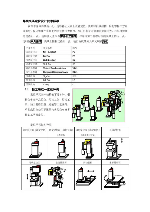
焊装夹具定位设计技术标准在白车身零件的面、孔、边等特征元素上设置定位、夹紧等机械结构,限制零件三方向自由度,保证零件在夹具上的重复性位置精度,保证白车身质量和质量稳定性。
白车身零件2.1 加工基准—定位种类定位单元基本结构有下述8种。
根据白车身产品特点、焊接工艺、焊接工具、加工基准类型、功能等工艺条件,单独或组合使用下述结构实现白车身零件加工基准定位。
定位单元结构种类:2.2定位单元构成定位单元通常由定位块(定位销)、连接板、支座、夹紧块、夹紧臂、铰链、气缸、导向8种基本功能件组成,复杂定位单元需要增加限位块、导轨、二层支座等功能件(如下图所示)。
2.3(白车身零件)加工基准加工基准需要同时满足四大工艺(冲压、焊装、涂装、总装)使用,具有一致性。
加工基准在产品设计时通过工艺评审,最终确定,是完整产品组成的一部分。
按零件面、孔、边的几何特征,加工基准可以划分为:面基准—S(s)、孔基准—H(h)、边基准—E(e);按零件上几何元素功能,加工基准可以划分为:正基准、辅助基准、变换基准等;结合上述两种划分方法,加工基准划分为以下13种,便于使用和管理。
2.4加工基准—定位单元位置精度不同加工基准的定位精度要求不同。
分为三类:孔基准—定位销、面(边)基准—定位块、特殊辅助面基准—定位块。
(1)孔基准—定位销◆孔基准类型:◆定位销、连接板孔配合公差:h7/H7◆ 定位销位置公差:±0.1mm◆ 定位销连接处直径公差:h7◆ 连接板孔直径公差:H7(2) 面基准—定位块◆ 面基准类型:◆ 定位块位置公差:±0.1mm(3) 特殊辅助面基准—定位块◆ 特殊辅助面基准类型:◆定位块位置精度:+0/-0.5㎜e2.5 加工基准—定位单元刚性为保证制造质量的稳定性,要求定位单元的定位件(块、销)装配后其工作方向位置变化<0.1mm 。
既要保证夹具骨架(平台)的结构刚性,还需要保证定位单元的结构刚性。
LZKL焊装夹具技术规范有限公司企业标准焊装夹具技术规范2015年1月发布内部使用2015 年1月实施签字目录目录 (1)前言 (3)标准演变 (4)适用范围 (5)1 焊装夹具工艺分析 (6)1.1 焊装夹具工艺条件注入 (6)1.2 产品数模图纸分析 (7)1.3 制定焊装流程图 (7)1.4 焊装线布置 (8)1.5 工位时序图 (9)1.6 工位焊点分析,焊钳选型 (10)1.7 工位工装结构分析 (11)2 焊装夹具结构 (15)2.1 考虑因素 (15)2.2 设计方法与步骤 (16)2.3 结构组成 (17)2.4 命名规则 (17)2.5 底板(BASE) (18)2.6 夹紧器 (21)2.7 定位部件 (29)2.8焊枪导向及通过性 (36)2.9磁铁的使用 (38)2.10防呆装置 (38)2.11 防护装置 (40)2.12 起吊装置 (41)2.13 测量机构 (43)2.14 典型机构 (45)2.15辅助机构 (48)3 气路控制系统 (51)4 焊装夹具的制造、检测规范 (53)5 焊装夹具资料交付 (54)附录A(纯气控夹具气动原理图样图) (55)附录B(夹具常用命名规定) (57)前言夹具的作用及设计总体要求⑴焊装夹具在车身生产中的作用是:通过夹具上的定位销(基准销)、S面型块(基准面)、夹紧臂等组件的协调作用,将工件(冲压件或总成件)安装到工艺设定的位置上并夹紧,不让工件活动位移,保证车身焊接精度的一致性和稳定性.⑵操作者及维护者的安全必须首要考虑,工装设计及制造要求必须满足或超过国家规定的标准。
⑶工装设计必须考虑可靠性和可维护性。
⑷材料强度符合工装功能要求。
标准演变适用范围本标准规格了汽车焊装夹具的设计、制造、安装、调式与验收的技术要求。
本标准适用于柳州科雷工贸有限公司的汽车焊装夹具。
1 焊装夹具工艺分析1.1 焊装夹具工艺条件注入㈠产品数据包含有产品的数模、产品图纸(GD&T图或形位公差要求图)、产品焊接图(3D数模或图片表示,要能清楚表示出焊接的类型、数量、位置)。
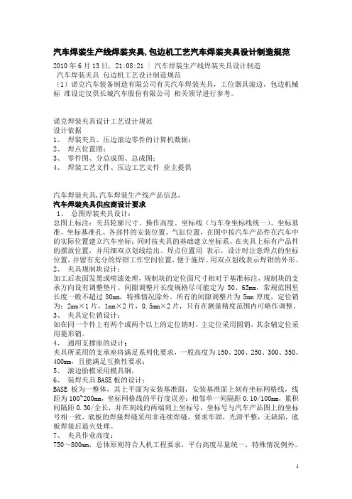
汽车焊装生产线焊装夹具,包边机工艺汽车焊装夹具设计制造规范2010年6月13日, 21:08:21 | 汽车焊装生产线焊装夹具设计制造汽车焊装夹具包边机工艺设计制造规范(1)诺克汽车装备制造有限公司有关汽车焊装夹具,工位器具滚边,包边机械标准设定仅供长城汽车股份有限公司相关领导进行参考。
诺克焊装夹具设计工艺设计规范设计依据1、焊装夹具、压边滚边零件的计算机数据;2、焊点位置图;3、零件图、分总成图、总成图;4、焊装工艺文件、压边工艺文件业主提供汽车焊装夹具,汽车焊装生产线产品信息,汽车焊装夹具供应商设计要求1、总图焊装夹具设计:总图上标注:夹具轮廓尺寸、操作高度、坐标线(与车身坐标线统一)、坐标基准、坐标基准孔、各部件的安装位置、气缸位置,在图中按汽车产品件在汽车中的实际位置建立汽车坐标;同时按夹具的基础建立坐标系。
在夹具上标有产品件的摆放位置,并用细双点划线绘出。
焊点位置用表示,设计时注意焊点的坐标位置,并留有充分的焊钳工作空间位置,便于施焊。
用双点划线表示焊钳的外形。
2、夹具规制块设计:加工后表面发黑或喷漆处理,规制块的定位面尺寸相对于基准标注,规制块的支承方向设有调整垫片。
间隙调整片长度规格尽可能定为50、65mm,常规范围里长度一般不超过80mm,特殊情况除外。
所有的间隙调整片为5mm厚度,定位销为:2mm×1片,1mm×2片,0.5mm×2片,只有在测量精度范围内可略作调整。
3、夹具定位销设计:如在同一个件上有两个或两个以上的定位销时,主定位采用圆销,其余辅定位采用菱形销。
4、通用支撑座的设计:夹具所采用的支承座将满足系列化要求,一般高度为150、200、250、300、350、400mm,且能满足互换性要求;5、滚边胎模采用模具钢,6、装焊夹具BASE板的设计:BASE板为一整体,其上平面为安装基准面,安装基准面上刻有坐标网格线,线距为100~200mm,坐标网格线的平行度误差:相邻单一间隔距0.10/100mm,累积间隔距0.30/全长,并在刻线的两端刻上坐标号,坐标号与汽车产品图上的坐标号相一致,底板的焊接焊缝采用非连续焊缝,要求牢固,光滑平整,无缺陷,底板焊接后退火处理。
解放卡车焊接夹具通用技术要求中国第一汽车集团公司发布Q/CAXX—XXXX—2012前言本部分由一汽解放汽车有限公司卡车厂工艺技术室提出。
本部分由一汽解放汽车有限公司规划部归口。
本部分由一汽解放汽车有限公司卡车厂工艺技术室负责起草。
本部分主要起草人:崔颖、李丽芹、冯唯。
本部分首次发布。
IQ/CAXX—XXXX—2012解放卡车焊接夹具通用技术要求1 范围本部分规定了主要用于解放卡车焊接夹具的通用要求。
本部分适合于解放卡车焊接夹具的设计与制造。
2 规范性引用文件GSB05-1426-2001 国标色卡3 解放卡车焊接夹具通用技术标准要求所有焊接夹具必须满足将零合件按产品要求定位组合,在夹紧状态下完成焊接工艺过程,每个工序合件和总成都要达到产品要求,控制在产品规定的公差范围内,最终按照生产节拍要求生产出合格产品;要求焊钳接近性好;重要表面焊点要加铜垫板,要求铜垫板厚度不小于8mm;所有装配夹具满足工艺要求。
3.1 坐标系的建立夹具设计的坐标系原则上与车身设计坐标系一致。
以汽车前轴中点为坐标原点,向上为Z坐标正向,向后为X坐标正向,面向前方右侧为Y坐标正向;反向为负。
当需要在某些特殊部位布置夹紧点时,为了方便尺寸标注,需要把局部坐标旋转变换,原则上所采用的旋转基点(轴),应取在车身设计坐标50线倍数的交点上。
3.2 基准要求1)为了保证在产品加工过程中基准的统一,需按照RPS基准系统来确定夹具主定位基准(改造焊接夹具需延用原有基准,并保证统一),定位孔及销的圆菱性必须与RPS一致,定位面可在RPS同一基准面上进行适当调整(50mm以内),且必须保证前后工序定位基准统一。
2)对于夹具的BASE板,其上表面为基准面,并且与车身坐标一个方向上的百线重合。
沿基板表面是车身坐标的另外两个方向,应加工出两道互相垂直的基准槽,并用钢印予以标记。
3)对于定位支座,高度方向的基准是支座底面,其余两个方向的基准分别是支座对称中心和底面安装基准销孔中心线。
焊装夹具类生产技术要求1范围本标准规定了汽车焊装夹具的设计、样品测试、试生产、大批量生产、性能要求及其他技术要求、标志与包装等技术要求。
本标准适用于汽车焊装夹具的生产制造。
2规范性引用文件下列文件中的内容通过文中的规范性引用而构成本文件必不可少的条款。
其中,注日期的引用文件,仅该日期对应的版本适用于本文件;不注日期的引用文件,其最新版本(包括所有的修改单)适用于本文件。
GB15760金属切削机床安全防护通用技术条件GB/T120.2内螺纹圆柱销淬硬钢和马氏体不锈钢GB/T191包装储运图示标志GB/T3766液压传动系统及其元件的通用规则和安全要求GB/T5226.1机械电气安全机械电气设备第1部分:通用技术条件GB/T5900.1机床主轴端部与卡盘连接尺寸第1部分:圆锥连接GB/T5900.2机床主轴端部与花盘互换性尺寸第2部分:凸轮锁紧型GB/T5900.3机床主轴端部与花盘互换性尺寸第3部分:卡口型GB/T7932气动对系统及其元件的一般规则和安全要求GB/T9969工业产品使用说明书总则GB/T13306标牌3术语和定义下列术语和定义适用于本文件。
夹具clamp机械制造过程中用来固定加工对象,使之占有正确的位置,以接受施工或检测的装置。
焊装夹具welding fixture为保证焊件尺寸,提高装配精度和效率,防止焊接变形所采用的夹具。
4夹具设计夹具组成及操作、控制方式4.1.1夹具组成4.1.1.1焊装夹具包含若干个夹紧单元和基板,并在需要的地方增加举升机构、旋转机构以及翻转机构的辅助机构。
4.1.1.2焊装夹具主要零部件有:基板、L-板、H腿、规制块、夹紧臂、型块、垫片、定位销、定位销托架。
4.1.2操作、控制方式夹具操作方式为气动;控制方式为气控。
数据建模4.2.1夹具在设计前应开展实地测绘,获取实车数据,并建立数据模型。
4.2.2夹具应根据白车身建模实际结果,结合开孔位置及用户需求,精准定位以确定白车身开孔位置,从而得出定位点的支撑点及限位点等数据。
××××轿车白车身焊接用工装技术要求验收标准一汽轿车股份有限公司产品部 发布Q/CAF01 0300 P-1-2006前言为保证轿车白车身焊接用工装质量,提高白车身焊接质量,规范轿车白车身焊接用工装的验收,特制定本标准。
本标准由一汽轿车股份有限公司技术部提出并归口。
本标准由一汽轿车股份有限公司技术部负责起草。
本标准主要起草人:赵卯、崔海滨、孙红英Q/CAF01 0300 P-1-2006索引1范围2规范性引用文件3术语和定义3.14 验收标准使用注意事项4.1 验收标准使用要领4.2 其他注意事项4验收标准5.1 工艺装备验收通项5.2焊接夹具验收项目5.2.1 第一阶段:K2结束后5.2.2 第二阶段:配线、配管完成后5.2.3 第三阶段:接通气源,夹具不带工件动作确认5.2.4 第四阶段:夹具载件动作确认5.2.5 第五阶段:一汽轿车拆箱、安装、还原5.2.6 第六阶段:一汽轿车复检Q/CAF01 0300 P-1-2006轿车白车身焊接用工装技术要求-验收标准1范围本标准规定了轿车白车身焊接用工装的验收标准。
本标准适用于轿车公司白车身焊接用工装验收。
2规范性引用文件下列文件中的条款通过本标准的引用而成为本标准的条款,其最新版本适用于本标准。
MES E6032 TG02MES E6032 TG03MES E6032 TG04MES E6032 CB02MES E6032 CB06MES E6032 CC03MES E6032 CC04MES E6032 CC05MES E6032 FA04MES E6032 HA033 术语和定义3.1 工艺装备:实现制造加工工艺要求的设备。
Q/CAF01 0300 P-1-2006 4 验收标准使用注意事项4.2.1 左件与右件的工装设备单独验收,即一套工装对应一份验收单;4.2.2 原则上各阶段使用同一验收单,由技术部存档;4.2.3 由技术部负责组织各阶段的验收工作Q/CAF01 0300 P-1-2006 5 验收标准Q/CAF01 0300 P-1-2006 5.2 焊接夹具验收项目Q/CAF01 0300 P-1-2006 5.2.2 第二阶段:配线、配管完成后Q/CAF01 0300 P-1-2006 5.2.3 第三阶段:接通气源,夹具不带工件动作确认Q/CAF01 0300 P-1-2006 5.2.4 第四阶段:夹具载件动作确认Q/CAF01 0300 P-1-2006Q/CAF01 0300 P-1-2006 5.2.5 第五阶段:一汽轿车拆箱、安装、还原Q/CAF01 0300 P-1-2006 5.2.6 第六阶段:一汽轿车复检Q/CAF01 0300 P-1-2006。
Resistance Spot WeldingDesign, CalculationUncoated and Coated Steel SheetsPrevious issuesVW 01105-1: 1977-05, 1993-12, 2003-05, 2003-06, 2003-11, 2007-03ChangesThe following changes have been made as compared to VW 01105-1: 2007-03:–Technical responsibility changed–Appendix A "Limits for quality levels" added–Referenced standards updatedContents PageScope (2)Terms and definitions (3)Spot welding (3)Heat-affected zone HAZ .............................................................................................3Unaffected base material (3)Design (3)Spot-welded joint (3)Weld joint (3)Sheet thickness (3)Requirements (3)Materials (welding suitability) (5)Design (weld reliability) (6)Position of the weld spots ..........................................................................................6122.12.22.32.42.4.12.4.22.4.333.13.23.2.1Group Standard VW 01105-1Issue 2010-02Class. No.:04815Descriptors:welding, spot welding, resistance spot welding, weld spot, sheet metal, steel, sheet steelCheck standard for current issue prior to usage.This electronically generated standard is authentic and valid without signature.The English translation is believed to be accurate. In case of discrepancies the German version shall govern.Numerical notation acc. to ISO practice.Page 1 of 32Technical responsibility Standards DepartmentGQL-LM1Dr. Knud Nörenberg Tel.: +49-5361-9-73623GQL-LM Dr. Stephan Eisenberg EKDV/4 Uwe Fischer EKDVTel.: +49-5361-9-27995Manfred Terlinden Confidential. All rights reserved. No part of this document may be transmitted or reproduced without prior permission of a Standards Department of the Volkswagen Group.Parties to a contract can only obtain this standard via the B2B supplier platform .© Volkswagen Aktiengesellschaft VWNORM-2008-12l QU E L L E : N O L I SWeld sequence ..........................................................................................................7Arrangement of spots (spot position) .........................................................................7Spot spacing ..............................................................................................................7Design examples and dimensions .............................................................................8Tolerances ...............................................................................................................13Manufacturing (welding capability) ...........................................................................14Basics .......................................................................................................................16Minimum shear force (F S ) .........................................................................................16Cross-tension force F K .............................................................................................17Peeling force F peel .....................................................................................................17Torsion .....................................................................................................................18Static and dynamic loads .........................................................................................18Process assurance ...................................................................................................19Weld spot geometry .................................................................................................19Number of weld spots ..............................................................................................23Surface quality class for spot-welded sheets ...........................................................23Drawing entries ........................................................................................................24Referenced documents ............................................................................................25Limit values for quality levels ...................................................................................263.2.23.2.33.2.43.2.53.2.63.344.14.24.34.44.54.64.6.14.6.24.6.356Appendix AScopeThe following basic regulations are based on experience with low to high degrees of mechanization,on test results, as well as on standards and technical regulations, e.g. DVS 2902-1, DVS 2902-2,DVS 2902-3.This standard is used for the design, calculation and workmanship of resistance-spot-welded sheet steel constructions subject to both static and dynamic loads. The joints used in these constructions are hereinafter referred to as "spot-welded joints".This standard covers resistance spot welding (reference number 21 acc. to DIN EN ISO 4063) on single-shear spot-welded joints with a sheet thickness ratio ≤ 3 : 1 for a thickness of 0,5 mm to 4,0 mm,as well as quality characteristics of single-spot and multiple-spot-welded joints. Larger sheet metal thicknesses and ratios are possible in agreement with the engineering departments. The nugget diameter is always determined by the thinnest sheet thickness.Sheets according to DIN EN 10139, however, are to be used only if their thickness does not exceed 3,0 mm.The introduction of zinc-coated sheets, e.g., according to DIN EN 10142 or DIN EN 10292, and the use of high-strength and higher-strength steels require higher electrode forces. This, in turn, may result in the necessity for larger electrode tip and electrode shank diameters (16 mm and 20 mm).When these electrodes are used, the weld nugget moves further away from the root face in the case of angled spot-welded flanges. However, as the distance between the weld nugget and the root face increases, component rigidity and strength decrease.Further requirements for (resistance) spot-welded joints are included in:–VW 01105-2 Resistance Spot Welding; Aluminum Materials,–VW 01105-4 Multiple-Sheet Joints; Dual- and Multiple-Shear JointsThe procedures described in the Test Specifications PV 6702 and PV 6717 are decisive for the quality audit of spot-welded joints.1 Page 2VW 01105-1: 2010-02Terms and definitions Spot weldingIn resistance spot welding, the weld zone between the parts to be joined is heated to the melting point using resistance heating with electrode force acting simultaneously. Size, shape and position of the melted base material depend on the temporal and spatial interaction of the heat quantities generated and dissipated in the weld zone and its surroundings. Under the influence of the electrode force, the workpieces are joined when the melt solidifies. The welded joint in the shape of a "weld nugget" that develops during this process is referred to as a …weld spot“ (Figure 26) that joins the parts (Section 2.4.2). The nugget diameter d L is the diameter of the melted material in the joining plane that is measured on the microsection.Heat-affected zone HAZArea of the base material that remains solid but experiences changes in microstructure due to the thermal energy applied during spot welding.Unaffected base materialArea of the base material that has experienced no recognizable changes in microstructure due to the energy applied during spot welding.Base materials that do not differ significantly in their chemical composition and suitability for spot welding are considered materials of the same type. Base materials that differ significantly in their chemical composition and suitability for spot welding are considered as different types of materials.Design Spot-welded jointThe spot-welded joint is a connection of two or more parts joined directly at the weld joint by one or more "weld spots" or "spot seams". The parts involved are designated on drawings as an ASSY (assembly) or WA (welded assembly).Weld jointThe weld joint is the configuration in which the parts are joined to each other by spot welding. The respective joint type is determined by the design relationships of the parts to each other.Sheet thicknesst 1 and t 2 are sheet thickness values of the single-shear spot-welded joint. For the purpose of uniform definition, especially for calculation, the thinnest sheet or the thinnest outer sheet of the joint must always be designated as t 1 if there are different sheet thicknesses. The thickest sheet of the joint is designated as t 2.RequirementsEach spot-welded construction must be "suitable for welding" in order to achieve the greatest possible design strength during manufacturing in the sense of the design goal with adequate safety and op‐timum cost-quality ratio. This means that the dimensions in the spot welding equipment, the electrode 22.1 2.2 2.3 2.42.4.1 2.4.2 2.4.3 3 Page 3VW 01105-1: 2010-02space requirement, as well as the accessibility of the workpiece must already be taken into consid‐eration during advance engineering. The weldability depends on three influencing variables:–welding suitability (material),–weld reliability (design),–welding capability (manufacturing).All three criteria have the same priority for weldability, see Figure 1. For a definition, please also refer to DIN Technical Report ISO/TR 581 "Weldability - Metallic Materials, General Principles".Figure 1 – Schematic representation of the weldability of spot-welded jointsPage 4VW 01105-1: 2010-02Materials (welding suitability)The welding suitability is a material property. Materials are suitable for welding if the material´s chemical composition allows a welded joint that meets the requirements set forth in the respective standards to be produced.For a first estimation of the welding parameters of a joining task, it is recommended to prepare a weldability lobe (time/current diagram, Figure 2) stating the limit lines for the minimum and maximumnugget or spot diameters for a constant electrode force and shape, see also DIN EN ISO 14327.Figure 2 – Weldability lobeFor estimation of the welding parameters, it is recommended to select the welding time and current values such that the following current differences result between the limit lines of d L min or d P min and d L max or d P max :–Δ ≥ 1,2 kA for resistance spot welding equipment with tip cutting device,–Δ ≥ 1,5 kA for resistance spot welding equipment without tip cutting device.The chemical composition basically influences the microstructure, hardening, nugget formation and strength of the spot-welded joint.The less the material-related factors have to be considered in manufacturing and design, the greater the welding suitability of a material within a material group (see DVS 2902-2).Testing of nugget position, nugget shape, and welding range is required for spot-welded joints of mixed materials (especially connections between unalloyed/low-alloyed steels and austenitic steels).All steels with a C content of up to 0,25% (max. 0,3%) are suitable for spot welding. In many cases,the equivalent carbon content (CE) is used for determining the welding suitability (hardening) of un‐alloyed and low-alloyed steels. According to DVS 2902-2, the following equation applies to a first estimation of the hardening of the weld metal:CE = C + Mn/6(1)3.1 Page 5VW 01105-1: 2010-02Figure 3 – Maximum hardness of the weld nugget as a function of the equivalent carbon content Figure 3 is an example illustrating the interdependence between the maximum hardness of the weld nugget and the equivalent carbon content.Special measures (e.g. reheating, multi-pulse welding, etc.) may be necessary for alloyed steels due to the alloying elements that influence hardness. Therefore, their use has to be agreed upon with the responsible engineering departments and tested separately.A hardness increase factor of ≤ 3,5 is recommended as the limit value for the hardness in both the weld nugget and the HAZ.Example:(2)The maximum hardness in the weld nugget and the HAZ must not exceed the value of 550 HV 0,2.See also DVS 2905.Design (weld reliability)Weld reliability is of particular importance for design. The design-related weld reliability is mainly influenced by the material and to a slight extent by manufacturing. Weld reliability is provided if, with the material used, a component remains functional under the intended operating conditions due to its design.Position of the weld spotsThe position of the weld spots must be specified by Design Engineering in consultation with Produc‐tion and Planning departments. If possible, the electrodes should contact the part perpendicular to the part surface. Otherwise, i.e. if they contact the part surface at a different angle, the nugget diam‐eter may be significantly smaller and elliptical.3.2 3.2.1 Page 6VW 01105-1: 2010-02The key criteria for the distance between the weld spot and the perpendicular flange are the minimum distance A = 2,0 mm from the current-carrying parts, the largest radius R i , as well as the electrode shank diameter d S or electrode tip diameter d K .Please refer to the drawing or DIN ISO 2768-1 for positional tolerances of the weld spots (spot spacing tolerance).Further information on the design of spot-welded joints can be obtained from DVS 2902-3.Weld sequenceContinuous rows of weld spots created using only one welding device must have spacings no smaller than 25 mm. For narrower spot spacings, the welding to gap method must be used (to prevent sub‐sequent spots from being too small or loose, see Figure 4).Arrangement of spots (spot position)The arrangement of spots must be selected such that the force F to be transferred is distributed as uniformly as possible over all spots. If the load distribution is not uniform, there will be a negative effect on both the vibration resistance and the crash behavior.With multiple-row spot seams, the spot arrangement is to be agreed upon with the Design Engineer‐ing, Calculation, Strength, Planning and Production departments.Spots that cannot be welded properly due to difficult accessibility are to be avoided (see Figure 7)."Quarter, third, half and three-quarter spots" reduce load bearing capacity. In checked exceptional cases, a defined portion of half and three-quarter spots can be permitted by the Testing department (Vehicle Strength and Vehicle Safety) in certain areas. This must be noted separately in the assembly drawing (Figure 29).Spot spacing The spot spacing e is the distance between the centers of two adjacent weld spots (Figure 4 and Figure 5). The spot spacing e Neb indicates the distance below which the shunt can no longer be ignored during the welding process.The shunt increases when–spot diameter,–sheet thickness,–electrode force, and –electrode contact surface increase, and when –the spot spacing decreases.Depending on the size of the shunt, the welding current must be increased more or less in order to create weld nuggets with the same diameter. The portion of the current that flows over spots of the seam that are already present does not contribute to heating the actual weld area. Therefore, the nugget diameter will be smaller starting from the 2nd spot of a seam if the spot spacing is too small and the setting data are constant. The influence of the shunt can be compensated for with the use of programmable and process-regulating controls. Generally, the following applies: e ≥ e Neb 4 x d L can be used as a reference value for the spot spacing e .Shunt can be ignored for a spot spacing e ≥ 10 (t 1 + t 2). In the case of multiple-row joints the following applies as a rule: e ≈ 5 x d L3.2.2 3.2.3 3.2.4 Page 7VW 01105-1: 2010-02Figure 4 – Left: double-row offset single-shear spot seam; right: double-row double-shear spot seam Figure 5 – Prevention of shunt in case of spot spacings that are too smallFigure 6 shows different forms of shunt.Figure 6 – Forms of shuntLegenda)Shunt at the sheet metal due to electrode contact b)Shunt via the centering pin (due to close distance)The Figure does not show shunt forms caused by c)clamps,dthe transformer grounding,e)the fixture.Design examples and dimensions Designs with poor accessibility are to be avoided, since specifically shaped electrodes and/or elec‐trode arms would be required (Figure 7 and Figure 12).3.2.5 Page 8VW 01105-1: 2010-02Figure 7 – Examples of unfavorable and favorable accessibility for the welding electrodes at the weldflangesOverlap Overlap b is the width of the contact surface of the weld flanges on the sections. The planes of thecontact surfaces must be parallel and touch each other (Figure 8).b is the shortest distance between the limit lines. The following applies: b ≥ 2v.Figure 8 – Left: single-row single-shear spot seam; right: double-row single-shear spot seamSeam spacing f For multiple-row spot seams, the seam spacing f is the shortest distance between the spot centers of adjacent seams (Figure 8 right). The following applies in general: f ≥ e.Seam length l The seam length l is the distance between the spot centers of the first and last spots of a spot seam (Figure 8).Edge distance v The edge distance v is the distance between the weld spot center and the closest limit line of the contact surface (Figure 9).3.2.5.1 3.2.5.2 3.2.5.3 3.2.5.4 Page 9VW 01105-1: 2010-02The following applies as a rule: v min = 1,25 x dL minFigure 9 – Edge distanceFlange width a The flange width a (Figure 10) is the value that is to be complied with in manufacturing, so that a)the position of the weld spot is not too close to the edge of the sheet metal,b)the welding equipment (electrode tip and shank) does not create any shunt to the bent sheet,c)the selected bending radius of the sheet is small enough to provide a longstraight portion of the flange width to ensure a sufficient contact surface forthe welding electrode.The flange width is to be agreed upon between Design Engineering, Planning and Production de‐partments.For calculation, see VW 01105-1 Supplement 1 "Resistance Spot Welding; Calculation of Flange Width ".In exceptional cases, it is possible to deviate from the flange width calculation. If this is the case, the flange width must be agreed upon between Design Engineering, Planning and Production depart‐ments.Figure 10 – Flange widthsFor multiple-row spot seams, the flange width a is to be increased according to the seam spacing f.The flange width is measured from the end of the flange to the angled sheet and is composed of the edge distance v and the clearance FM, as well as the tolerance T G .3.2.5.5 Page 10VW 01105-1: 2010-02Flange offset iThe flange offset i is the maximum projection of the primary flange with respect to the secondary flange, e.g. for the mounting of seals (Figure 10). The secondary flange must not protrude over the primary flange on the trim edge.Flange heights c and h, offset gThe dimensions c and h (Figure 10) take into consideration the dimensions of the spot weldingequipment, the electrode space requirements and the workpiece accessibility in manufacturing (see also Figure 13).The dimension g specifies the maximum permissible offset (Figure 11).The values must be agreed upon between Design Engineering, Planning and Production depart‐ments.Flange and overlap spacing kThe flange and overlap spacing k is the distance between overlap b and tangent line (Figure 11).Figure 11 – Offset g, spacing kThe following applies to k min : k ≥ 2,0 mm The following applies to g min : g ≥ sheet thickness3.2.5.6 3.2.5.73.2.5.8Flange geometryTable 1 – Weld flange geometry as a function of sheet thickness t min and welding condi‐tions (all dimensions in mm)Sheet thick‐nessSpot spacing Flange dimensions DiameterClearanceFlange width t mine Nebv min b min i g max k mind Kd SFMa0,5 to 0,6103,36,61,0–1,01,1213138,515,3> 0,6 to 0,8123,97,81,0–1,01,316181118,4> 0,8 to 1,0154,38,61,5–1,51,518,8> 1,0 to 1,2184,89,61,5–1,51,719,3> 1,2 to 1,5245,310,61,5–1,52,019,8> 1,5 to 1,6275,611,22,0–2,02,520,1> 1,6 to 2,0276,312,62,0–2,02,520201221,8> 2,0 to 2,5366,813,62,0–2,03,022,3> 2,5 to 3,0457,615,22,0–2,03,5241425,1> 3,0 to 3,5548,116,22,5–2,54,725,6> 3,5 to 4,0638,817,52,5–2,54,726,3Legend:v min = 1,25 d L min Edge distance (Figure 9) including tolerance b ≥ 2 v and b ≥ a - r Overlap (Figure 9)i Flange offset (Figure 10)g max Offset of the overlap (Figure 11)k min Flange and overlap spacing (Figure 11)d K Electrode tip diameter d SElectrode shank diameterFM = d S /2 + A Clearance for electrode shank diameter a ≥ v min + FM + T GFlange width, influence of electrode (f A=2; D shank )with T G = 3,5NOTE 1 Since the flange width values specified in Table 1 depend on several factors, and since at least T G must be agreed upon between Design Engineering, Planning and Production departments (see Section Section 3.2.6), the values still have to be corrected accordingly.Reference sheet thickness t vFor joints with different sheet thicknesses (t 1 ≠ t 2), the reference sheet thickness t v may be used instead of t min for determining the welding parameters.t v = 0,8 t 1 + 0,2 t 23.2.5.9 3.2.5.103.2.6TolerancesTolerance values must be agreed upon between Design Engineering, Planning and Production de‐partments.Trim tolerance T aThis value represents the trim tolerance during production of the individual part and must be included in the calculation.General body-in-white tolerance T RThis value considers the general tolerances in body construction, including the inaccuracies of in‐dustrial robots and must be included in the calculation.Design-related tolerance compensation T KThe value considers the flange displacements that are provided for secondary flanges and must be included in the calculation.Equipment tolerance T VThis value considers the repetition accuracy of the equipment and must be included in the calculation. Overall tolerance T GThe overall tolerance is made up of the tolerances T a, T R, T K and T V described above to the extent that these have to be considered.T G = T a + T R + T K + T VA total allowance of T G = 3,5 mm has been chosen for the calculation in Table 1.Manufacturing (welding capability)Care must also be taken in design to ensure that the component is capable of being welded (manu‐facturing-related weld reliability). It must be possible to produce the planned welds properly under the state-of-the-art manufacturing conditions.During the design of components, the following manufacturing aspects should be taken into consid‐eration:–If the designs require operating equipment with long arms spaced far apart, it must be determined early in the process whether the available welding equipment is suitable for this purpose.–If possible, the designs must allow short, straight and rigid arms, electrode brackets and elec‐trodes to be used (Figure 12).Figure 12 – Examples of electrode arm shapes to be avoided–Refer to VW 01105-4 for double-shear and multiple-shear joints.–The distance between the outer diameter of the electrode and/or the electrode bracket and theinner edge of the sheet must be at least (2 + 0,5) mm (Figure 13). Other specifications must be agreed upon between the responsible specialized departments.Figure 13 – Poor weld quality caused by electrodes that spring back and slide–During the welding process of high-strength and highest-strength sheets, the electrodes normally do not penetrate considerably into the base material. As a result, the risk of electrode sliding is increased. Especially if pneumatic electrode holder drives are used, it is important that the elec‐trodes are placed perpendicularly and that the electrode holder is as rigid as possible.–During welding of spot seams, the welding sequence must be selected such as to avoid the formation of cavities between the sheets (Figure 14).3.3Figure 14 – Welding sequence to avoid the formation of cavities–The electrode axis must be perpendicular to the sheet surface (90° ± 1°) (Figure 16, Figure 18).Figure 15 – Not per‐missible Figure 16 – Favor‐able Figure 17 – Permissi‐ble Figure 18 – Favor‐able–If asymmetrical electrode tips (Figure 17) are used, special measures are required in series production operation to ensure the proper alignment of the working surfaces (freedom from ro‐tation, orientation during tip change, special electrode tip milling cutters).BasicsDifferent types of loads occur depending on the design of a component (Section 2.4):–shear tension (Figure 19)–cross tension (Figure 20)–peeling tension (Figure 21)–torsion (Figure 22)If possible, spot-welded joints should only be loaded with shear tension since the highest forces per weld spot can be transferred with this type of load. Therefore, pure cross or peeling tensions and/or torsion are to be avoided.Minimum shear force (F S )For a single-shear joint, the shear force F s generates a bending moment M b = F s r s which increases with increasing load and also produces a portion of the cross tension force F K . r sis set as follows:Figure 19 – Shear tensionLegend A Prior to tensile testB After tensile test (exaggerated)C Outer notchF K Portion of the cross tension force of F max F SPortion of the shear force of F maxBecause of the realistic verification of requirements and the low variation of the test results, the cal‐culations of the spot-welded joints are based on the minimum shear force F s min that was determined from the shear test according to PV 6702:4 4.1F s min = F max - 2 s in kNLegend s Standard deviationF maxMean value of the maximum force determined in the shear test ac‐cording to DIN EN ISO 14273(3)Cross-tension force F KFigure 20 – Cross tensionWith this type of stress, the permissible load F K is only 60% of the shear force F min..The following applies according to DVS 2902-3 (to materials according to DIN EN 10130)F K ≤ 0,6 F min(4)Peeling force F peelFigure 21 – Peeling tensionWith this type of stress, the permissible load F peel perm is only 20% of the shear force F min as set forth in Table 2 and DVS 2902-3.F peel perm ≤ 0,2 F min(5)4.24.3TorsionFigure 22 – TorsionA durable joint is achieved with at least two weld spots, since, with twisting around one spot, the transferable torque M t is too low. Designs with only one load-bearing spot are not permissible.Static and dynamic loadsA basic distinction is made between calculations with static or dynamic loads. The formula relationship previously specified is used for calculation of static load.The following information applies to the proof of sufficient strength of dynamically loaded components:–Because of as yet inadequate knowledge about the influence of the design of the joint and the uncertainties in calculation, the load carrying capacity of the joints for vibration loads must always be verified through testing.–With a given material thickness, the service life of a joint depends on the load amplitude, the R value (stress ratio) and the type of load (Figure 23). The type of load may be shear or peeling.Cross tension and torsion usually do not occur. Generally no type of load occurs alone and in pure form.Figure 23 – Load amplitude–The single-row single-shear joint is to be preferred.–Dynamic cross tension, peeling tension and torsion are to be avoided due to the low permissible tension.4.4 4.5。
汽车车身焊装夹具设计概述车身焊装夹具设计是汽车生产线上非常重要的一环,它们用于固定和连接车身部件,确保生产过程中的准确性和稳定性。
本文将对汽车车身焊装夹具设计进行概述,包括设计要求、设计过程、常用设计软件以及设计流程等方面进行详细介绍。
一、设计要求车身焊装夹具设计的主要要求包括以下几个方面:1.准确性:夹具应具有很高的准确性,能够确保焊装过程中不发生偏差和错位。
2.稳定性:夹具应能够稳定地固定车身部件,以进行焊接等操作。
3.可操作性:夹具应易于操作,并且能够适应不同车身部件的夹持。
4.可靠性:夹具的设计应具有足够的强度和刚度,以确保工作时不产生变形或破坏。
5.安全性:夹具应符合相关安全标准,并且在使用过程中不会对人员造成伤害。
二、设计过程车身焊装夹具设计的一般流程如下:1.需求分析:根据生产线的需求和具体车型的要求,确定夹具的功能和使用条件。
2.方案设计:根据需求分析的结果,制定初步夹具设计方案。
包括夹具的整体结构、夹持方式、工作面积、夹持力等。
3.详细设计:在方案设计的基础上,进一步进行详细设计。
包括夹具各个部件的尺寸、材料选择、连接方式等。
4.制造与装配:按照设计要求制造夹具各个部件,并进行装配和调试。
5.试用与调整:在实际生产线上试用夹具,并根据使用情况进行调整和改进。
6.验收与使用:夹具通过验收后,正式投入使用。
三、常用设计软件进行车身焊装夹具设计时,常用的设计软件包括:1.Catia:该软件是一种三维设计软件,具有强大的建模和分析功能,适合进行夹具的结构设计和分析。
2.Autodesk AutoCAD:这是一种二维绘图软件,适合进行夹具的细节设计和图纸制作。
3.Solidworks:该软件具有强大的三维建模和装配功能,适合进行夹具的三维设计和装配模拟。
总结:车身焊装夹具设计是汽车生产线上不可或缺的一部分,它们的设计旨在确保车身部件在焊装过程中的准确性和稳定性。
设计夹具需要考虑准确性、稳定性、可操作性、可靠性和安全性等要求,并遵循一定的设计流程。
焊接夹具设计及制造标准总体技术要求:1、所有的夹具均采用气动控制压紧及车型转换方式(特殊规定可采用手动压紧器压紧或不用压紧)。
2、夹具应保证可靠的定位,防止变形,确保装配焊接质量和精度达到产品质量要求。
3、夹具工艺性能优良:各部件装配调整方便、人工焊接易于操作、产品取放方便、有足够的操作空间、操作方便快捷。
4、夹具上产品的高度应在700~800mm之间,对于四周焊接作业困难的应增加360°旋转转盘装置(特殊情况要求还需增加旋转定位锁紧装置)。
5、所有夹具须满足生产纲领的要求。
一、焊接件技术要求:1、焊缝高度不得<5mm、不允许有虚焊脱焊现象、重要部位须采用连续焊缝。
2、焊后清理焊渣、焊缝磨平。
所有部件在焊接后须退火消除应力再进行机加工。
-二、夹具底板1、夹具底板台面全部加工完成后厚度≮20mm,底板与槽钢等加强板料焊接前应校平,留有吊运点或叉车搬运位置,焊后应经退火处理和校平后再进行机加工等后续作业,加工完成后应对台面涂油处理。
2、加强筋规格选用标准(长方形的取最大值):(1)当夹具台面≤1400mm×1400mm时,底板的加强筋应采用10#以上槽钢;(2)当夹具台面>1400mm×1400mm时,底板的加强筋应采用16#以上槽钢;(3)当夹具台面>2000mm×2000mm时,底板的加强筋应采用20#以上槽钢;(4)底座周边的槽钢开口向外,中间加强筋用槽钢的间距不得>700mm.。
3、夹具台面的基准孔及网格坐标线:(1)基准孔:夹具台面上应留有两个坐标系的检测用基准孔,每个方向为两组,每组两个孔,孔径为φ10mm,孔距100mm.(在基准孔附近安装标牌或刻上钢字码,注明坐标数值)(2)网格坐标线:网格坐标线应与产品设计的坐标线对应。
深度及宽度均为0.5mm,间距为200mm.4、夹具台面的周边轮廓尽量与产品零件的轮廓相似,不得有突出的锐角,并尽量往里收,方便操作。
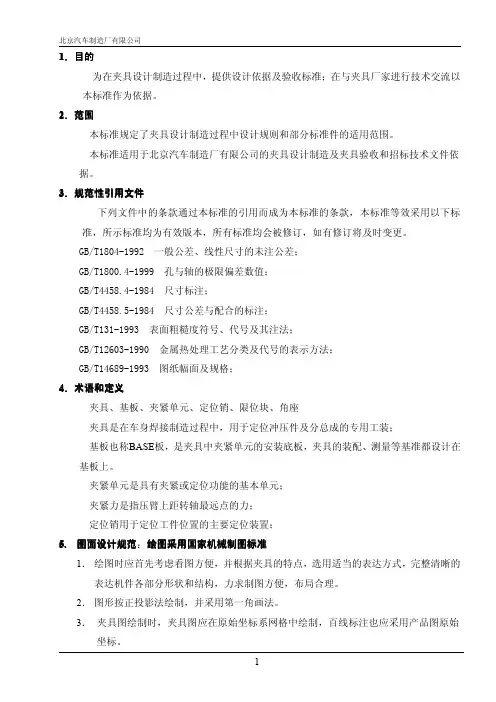
1、目的规范焊装夹具的设计、制造及管理,保持合格产品的质量状态。
2、范围本标准规定了公司内部设计与制作或委外设计与制作的夹具应遵守的基本规则。
本标准适用于本公司车辆产品的焊装夹具。
3、夹具制造精度标准3.1焊接夹具精度规格焊接夹具精度规格值见表1表1 焊接夹具精度规格*****机械有限公司3.2 底板及槽钢规格底座板、厚度规格值见表2表2 底座板、厚度规格单位:mm底座板、槽钢规格值见表3表3 底座板、槽钢规格值单位:mm3.3 通用支座规格3.3.1 夹具所采用的支承座(即三角架)须满足系列化要求,一般高度为150 mm、200 mm、250mm、300mm、350mm、400mm,且能满足互换性要求,最高不能超过600mm。
3.3.2 通用支座的主要面板厚为19 mm,加强筋板厚为16 mm 。
备注:1. 焊缝应为连续焊缝,并要求牢固、光滑平整、无缺陷。
2. 支座焊后应作退火处理,消除应力。
3. 通用支座板厚为加工后的最小设定尺寸.3.4 定位块厚度规格为16mm.4、夹具设计规范4.1 设计基准:提供图面资料内容:1)AD DATA(3D扫描) 2)成品图或数模图 3)单件图 4)焊接工艺流程 5)焊枪型式图面。
样件需求别纸另议。
4.2设计方式:4.2.1设计通则:2.1.1 装焊夹具设计采用模块化方式,要求满足焊接工艺。
2.1.2 夹具操作方便,设计完成后的工装系统必须符合人机工程学的要求。
2.1.3 夹具应有足够的装配、焊接空间,焊点在布置时应易接近。
2.1.4 夹具本身应有良好的制造工艺性和较高的机械效率。
2.1.5 所有工装夹具,控制面板及面板显示器的标签要求使用中文,如果使用英语应得到业主的批准。
2.1.6 所有图纸和文件中的尺寸、工程单位要求为公制,所有的紧固件都必须是公制的。
设计中使用非公制前都应得到公司的书面批准。
2.1.7 紧固件:采用国标内六角螺栓及定位销,所有的紧固的地方要进行防松处理。
汽车车身焊装夹具设计概述
汽车车身焊装夹具是用于汽车车身焊装过程中的零部件定位和固定的工具,在整个汽车制造过程中起到至关重要的作用。
车身焊装夹具的设计要考虑到汽车车身的形状和结构以及焊装工艺的要求,确保零部件的定位准确、稳定和可靠。
汽车车身焊装夹具设计的首要考虑因素是车身结构和形状。
不同型号的汽车车身具有不同的外形和结构特点,因此设计过程中必须充分理解汽车车身的结构和形状,以便确定合适的夹具类型和设计方案。
焊装工艺的要求也是设计夹具时需要考虑的重要因素。
不同的焊装工艺需要不同的夹具设计和操作方式,因此在设计过程中要考虑焊接的位置、角度和方向等因素,确保夹具能够满足焊装工艺的要求。
在汽车车身焊装夹具设计中,也需要考虑到夹具的结构和材料选择。
夹具的结构应该简单、坚固,便于安装和拆卸,并且具有一定的调整和固定功能。
材料的选择可以根据夹具的使用环境和负荷要求进行选择,一般使用高强度的钢材或铝合金。
还需要考虑到夹具的精度要求和使用寿命。
夹具的定位精度直接关系到车身焊装的质量和精度,所以夹具的设计要保证定位的准确性。
夹具的使用寿命也是一个重要的考虑因素,一般应该确保能够使用多次,并且能够经受长时间的工作。
在汽车车身焊装夹具设计中,还需要进行必要的试验和验证。
通过实际的焊装工艺和装配工艺试验来验证夹具的可行性和有效性,以确保夹具能够实现预期的效果。
汽车车身焊装夹具的设计必须考虑到车身结构和形状、焊装工艺的要求、夹具的结构和材料选择、精度要求和使用寿命等多个因素。
只有在综合考虑这些因素的基础上,才能设计出具有高效性和可靠性的夹具,提高汽车车身焊装的质量和效率。
一汽大众焊装车间上件工作业一汽大众焊装车间的上件工作是汽车生产过程中的关键环节之一。
焊装车间负责将汽车车身的各个部件进行组装和焊接,确保车身的结构牢固和安全性。
在上件工作中,焊装工人需要根据图纸和工艺要求,准确地将不同的车身部件按照一定的顺序进行装配。
这些部件包括车体骨架、车门、车顶、前后保险杠等。
在装配过程中,焊装工人需要运用各种机械设备和工具,如吊装设备、焊接机器人、气动工具等,确保部件的准确安装和牢固连接。
焊装车间的上件工作需要高度的操作技巧和经验,因为每个车型的上件工序都有所不同。
焊装工人必须熟悉各种焊接工艺,如点焊、气焊、焊接钢板等,以确保焊接质量和可靠性。
同时,他们还需要具备良好的空间感知能力和团队合作意识,因为焊装车间通常是一个繁忙的工作环境,需要与其他工人协同操作,确保整个车身装配过程的顺利进行。
上件工作对于整个汽车生产过程的质量和效率具有重要影响。
高质量的上件工作可以确保车身结构的牢固性和稳定性,提高车辆的安全性和驾驶舒适度。
同时,有效的上件工作可以提高生产效率,减少生产周期,降低生产成本,提高企业的竞争力。
为了保证上件工作的质量和效率,一汽大众焊装车间注重员工培训和技能提升。
他们为焊装工人提供系统的培训课程,包括焊接技术、安全操作规程、工作流程等方面的知识培训。
同时,他们也鼓励员工参与技能竞赛和交流活动,提高工人的技能水平和工作积极性。
总之,一汽大众焊装车间的上件工作是汽车生产过程中的重要环节。
通过高质量的上件工作,可以确保汽车的安全性和质量,提高生产效率和竞争力。
同时,通过员工培训和技能提升,可以不断提高上件工人的技术水平和工作质量。