动力定位系统介绍
- 格式:doc
- 大小:159.50 KB
- 文档页数:4
工程船舶动力定位系统失效原因及风险控制措施探讨随着社会对于海洋的开发和利用程度逐渐提升,对于工程设备以及定位技术的要求也逐渐提高,动力定位成为各国学者研究的重要课题,同时其在海洋资源应用过程中也承担着重要的角色。
动力定位系统是船舶或者工程平台能够通过自身的推进器来进行艏向的定位或者保持固定的位置,此动力定位系统通常应用于常规锚定定位方式不能够进行定位作业的情况下,是一种闭环性质的控制系统,其应用功能的实现能够对工程船舶的实际地理位置以及与期望的位置存在的偏差进行测量,并能够根据海浪的大小、风向等外界环境存在的干扰,将船舶回归到期望位置所需的助推力以及转矩进行科学的计算,进而实现工程船舶在海洋中的准确定位,保证其生产作业工作的有序进行。
标签:动力定位系统;失效原因;风险控制引言动力定位系统主要包括:传感器系统(主要应用于测量工程船舶的地理位置以及工程船舶受到的风浪等客观干扰情况)、控制器系统(控制器根据工程船舶的运行情况对预定位置偏差值进行计算,并根据力学关系测算回归预期位置需要的推力)、推动器系统(有多个推进器组成推力系统,能够根据测算结果对需要产生的推力进行科学的分配)。
工程船舶的动力定位系统失效的主要原因有动力偏移或者被动漂移,工程船舶在动力定位系统失效之后必须及时采取有效的应对措施,才能避免发生重大的事故发生,以DP钻井船为例,在动力定位系统失效之后,其钻井设备或者防喷器等设备可能会被损害,可能会对工程平台造成巨大的经济损失,还有可能造成海底井喷,进而造成严重的海洋污染事故,这些现象的出现都会影响工程船舶的正常工作,甚至给海洋环境造成不可逆的损害。
本文以DP鉆井船和DP铺管船为例,针对动力定位系统失效原因以及风险控制措施进行探究。
1 工程船舶动力定位系统失效原因分析由于目前的国际海事承包商组织的相关管理体系中,针对动力定位系统事故事件主要采用自愿上报的工作原则,因而在进行事故分析的过程中,存在一定的局限性,根据目前的数据资料显示,动力定位系统失效发生被动漂移事故的概率远大于动力偏移事故,不同的工程作业平台可能发生的定位系统失效事故也存在不同,根据不同的事故现象其失效的原因也存在差异。
DP定位船舶推力系统设计原则【摘要】动力定位系统(dynamic positioning system)是一种闭环的控制系统,其采用推力器来提供抵抗风、浪、流等作用在船上的环境力,从而使船尽可能地保持在海平面上要求的位置上[1]。
其中推力系统是动力定位系统的一个组成部分,用于产生力和力矩,来抗衡作用于船上的干扰力和干扰力矩。
本文阐述了推力系统设计时的几个原则。
【关键词】推力系统;推进器;设计特点1.引言推力系统是动力定位系统的执行机构,其作用是按照控制系统发出的一系列推力指令,形成一个时变的推力系统,以抵消外在的时变环境载荷[2]。
最新的动力定位系统的推力分配除了正常工作时的推力分配,还要求在系统部分受损的情况下,依然能够进行合理的推力分配以达到定位。
按照imo的分类[3],现有3种不同冗余度的动力定位系统:第一种是无冗余的动力定位系统,即系统受到一定的干扰和损坏就不能完成定位任务;第二种是有冗余的动力定位系统,即系统在单个设备有故障的情况下依然能够完成定位;第三种是有备份的动力定位系统,即在整个系统受到严重破坏的情况下,可以启动备用系统进行动力定位。
2.推力系统的组成动力定位的推力系统一般由若干个不同类型的推进器组成,根据动力定位设计的要求分别布置在船舶的不同位置,推进器类型主要包括主推进器[4],侧向推进器,全回转推进器等几种形式。
3.推力系统的设计传统的船舶推力系统的设计主要侧重于获得较高的航速和最佳的效率,而动力定位则偏向于在较低进速时的推力输出。
这就使得动力定位推力系统更加复杂,在尺寸选择、布置形式、推力分配和性能表现方面提出的更高的要求。
一般地,推力系统的设计主要按以下几个步骤来进行:3.1计算极限外环境载荷。
准确计算外环境力是能够设计出合理推力系统的基础,外环境载荷资料是否准确直接关系到设计的好坏甚至成败。
平台在海上所遭遇的环境条件主要有三种:风、波浪和海流。
由于动力定位只对低频水平载荷做出响应,除了考虑长周期变化的风和流载荷外,波浪载荷则只计及其中的低频慢变部分,即波浪漂移力。
浅析船舶动力定位系统的组成及应用发布时间:2022-12-19T07:56:40.231Z 来源:《科技新时代》2022年12期作者:陈龙韩朋刚刘欢蒙亚东只升震[导读] 船舶动力定位是在船舶需要定在某一坐标点时不在需要传统的定位锚机来固定,而是依靠一定的参考系统,如DGPS、罗经等,利用船舶自身的动力可以自动的维持在地球上的某一坐标点,这时DP控制系统依靠参考系统反馈回来的位置信息,风和流信息以及外力的信息,自动去控制主推进器,舵机,侧推等动力设备,维持在这个设定坐标点,这就是动力定位的简单解释。
(安装公司海洋石油202船)摘要:船舶动力定位是在船舶需要定在某一坐标点时不在需要传统的定位锚机来固定,而是依靠一定的参考系统,如DGPS、罗经等,利用船舶自身的动力可以自动的维持在地球上的某一坐标点,这时DP控制系统依靠参考系统反馈回来的位置信息,风和流信息以及外力的信息,自动去控制主推进器,舵机,侧推等动力设备,维持在这个设定坐标点,这就是动力定位的简单解释。
由于动力定位船舶的机动性、高效性,动力定位系统被广泛应用于海底管线检修,海洋电缆铺设、海洋石油平台守护、海洋钻井船、水下机器人跟踪、海底管线埋设等。
本文对工程船舶动力定位系统组成及作用进行分析。
关键字:动力定位参考系统自动控制工程船舶Abstract:This article is mainly about the Dynamic Position System, this system is different from the traditional position winch system. It depend on the DGPS, Gyro, Reference system, using the ship’s own ability hold a set position. The DP control system using the Reference system, calculate the external result forces, automatic control the thrusters, rudders to generate a opposite force, in order to keep the DP Ship positioning .Because of the better flexible and maneuvering, The DP control system is used more and more in the Marine Engineering construction. This article is mainly about the Dynamic Position System and the function.Key Words: Dynamic Position Reference System Automatic Control Engineering Ship1.动力定位系统工作原理的简单介绍20世纪60年代,随着海洋石油开发的需求,动力定位概念开始出现,美国Honewell公司将动力定位系统于1961年应用于第一条动力定位船舶CUSS1;近年来,随着海洋石油逐步走向深蓝,国际上各海洋石油公司发展目标、战略重心逐步转向深海领域;在海洋工程船舶的投资发展方向都是动力定位船舶,而动力定位系统是必不可少的利器。
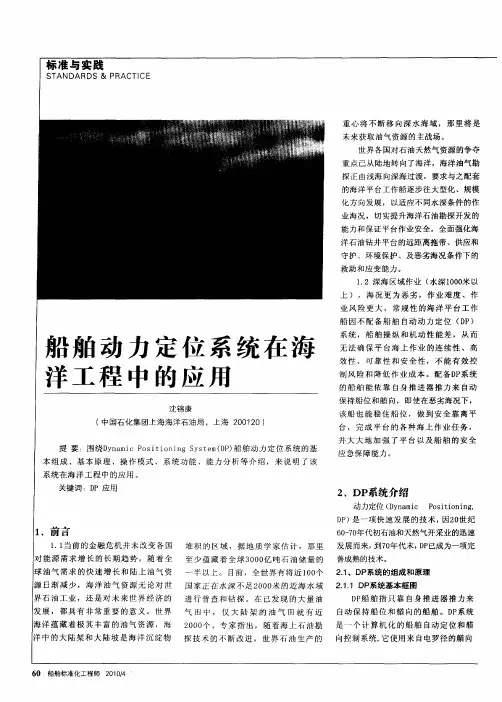
动力定位(D P)系统简介动力定位(DP)系统简介作者:王卫卫来源:《广东造船》2014年第01期摘要:随着海洋工程项目的蓬勃发展,动力定位系统(简称DP系统)的应用已越来越广泛。
本文对DP系统等级、工作原理以及根据船级社不同入级符号的设备配置等作了简单的介绍,希望能够对大家以后的开发设计及生产有所帮助。
关键词:DP;入级符号;特点;工作原理中图分类号:P751文献标识码:AInvestigation of Dynamic Positioning SystemWANG Weiwei( Guangzhou Shipyard International Co., Ltd. Guangzhou 510382 )Abstract: The application of Dynamic Positioning System (DP system) is more and more popular because of development of ocean project. The article introduce the level of DP system, work principle, the requirement of equipment according to different DP notations. I hope it is helpful to exploder, design and production in the future.Key words: DP;Classification notation;characteristic;work principle1前言动力定位系统(Dynamic Positioning System)简称DP系统,是从上个世纪70年代逐渐发展起来的,并逐步由浅水海域向深水海域发展,应用于各种海洋工程、海上科考、水下工程等领域。
随着船舶自动化程度越来越高,DP系统的定位能力以及自动化程度也越来越高,而以上各类领域的工程项目也越来越离不开带有DP系统的海上钻井平台和船舶。
动力定位(DP)系统简介
王卫卫
【期刊名称】《广东造船》
【年(卷),期】2014(000)002
【摘要】随着海洋工程项目的蓬勃发展,动力定位系统(简称DP系统)的应用已越来越广泛。
本文对DP系统等级、工作原理以及根据船级社不同入级符号的设备配置等作了简单的介绍,希望能够对大家以后的开发设计及生产有所帮助。
【总页数】3页(P52-54)
【作者】王卫卫
【作者单位】广州广船国际股份有限公司,广州510382
【正文语种】中文
【中图分类】P751
【相关文献】
1.动力定位(DP)系统简介 [J], 王卫卫
2.带DP-2附加标志的动力定位系统设计调试研究 [J], 卢俊奇; 葛妮
3.满足DP3动力定位要求的综合电能系统设计分析 [J], 贾颖晖; 韩朝珍
4.满足DP3动力定位要求的综合
电能系统设计分析 [J], 贾颖晖;韩朝珍
5.浅谈DP3船舶的动力定位系统电缆布置 [J], 刘伟平
因版权原因,仅展示原文概要,查看原文内容请购买。


船舶动力定位技术简述船舶动力定位技术简介动力定位技术背景随着船舶作业任务的复杂化,动力定位技术逐渐成为船舶自动化控制领域的研究热点。
目前,国际上主要的动力定位系统制造商有___、___、___等。
动力定位控制系统测量系统是指动力定位系统的位置参考系统和传感器。
位置参考系统主要采用DGPS,水声位置参考系统主要选择超短基线或长基线声呐,微波位置参考系统可选择Artemis Mk 4,张紧索位置参考系统可选择LTW Mk,激光位置参考系统可选择Fanbeam Mk 4,雷达位置参考系统可选择RADius 500X。
罗经、风传感器、运动参考单元等同样选择各专业生产厂家的产品。
控制技术动力定位系统的第一代产品采用经典控制理论来设计控制器,通常采用常规的PID控制规律。
第二代动力定位控制方法是以现代控制理论为基础的控制技术-最优控制和卡尔曼滤波理论相结合。
近年来出现的第三代动力定位系统采用了智能控制理论和方法,使动力定位控制进一步向智能化的方向发展。
智能控制方法主要体现在鲁棒控制、模糊控制、非线性模型预测控制等方面。
2001年5月份,挪威的___推出了一项新产品—绿色动力定位系统(Green DP),将非线性模型预测控制技术成功地引入到动力定位系统中。
Green DP控制器由环境补偿器和模型预测控制器组成。
环境补偿器的设计是为了提供一个缓慢变化的推力指令来补偿一般的环境作用力。
模型预测控制器是通过不断求解一个精确的船舶非线性动态数学模型,用以预测船舶的预期行为。
模型预测控制算法的计算比一般用于动力定位传统的控制器设计更加复杂且更为耗时,主要有三个步骤:1.从非线性船舶模型预测运动;2.寻找阶跃响应曲线;3.求解最佳推力。
控制器结构如图所示:在20世纪80年代初期,荷兰的Marin确定了推进器和动力定位的研究计划,并进行了动力定位的模型实验。
这些实验包括推进器和推进器之间的相互作用、推进器和船体之间的相互作用以及环境力和船舶的低频运动等内容。

船舶动态定位系统简介Introduction to DP 1 - IntroductionDynamic positioning (DP) is a rapidly maturing technology, having been born of necessity as a result of the increasing demands of the rapidly expanding oil and gas exploration industry in the 1960s and early 1970s. Even now, when there exist over 1,000 DP-capable vessels, the majority of them are operationally related to the exploration or exploitation of oil and gas reserves.动态定位系统是一个快速成熟的技术。
是基于1960年代到70年代油气勘探工业的需求的基础上产生的。
目前已经有超过1000艘以上的动态定位的船舶,其中绝大部分都后油气勘探有关。
The demands of the offshore oil and gas industry have brought about a whole new set of requirements. Further to this, the more recent moves into deeper waters and harsh-environment locations, together with the requirement to consider more environmental-friendly methods, has brought about the great development in the area of Dynamic Positioning techniques and technology.油气工业的需求给我们带来了一个全新的需求。
船舶动力定位系统的总体设计摘要:现如今,伴随着世界人口的急速增长,能源紧缺的问题正在变得越来越尖锐,这样的问题也引起了世界各国的广泛关注。
海洋领域的资源非常丰富,而且目前开发的程度并不高,这让越来越多的国家把目光投入到海洋资源开发之中,特别是深海资源开发上面。
而由于动力定位技术在深海开发上所起到的关键作用,现在已经成为近年来海洋开发最为热门的研究课题之一。
关键词:船舶动力,定位系统,设计探究1前言随着当前船舶与海洋工程的不断开发和快速发展,动力定位系统已然广泛应用于多种船舶和海洋平台上,并在其中发挥了重要的作用。
所谓动力定位系统,即是指船舶在不借助锚泊系统的作用下,通过测量系统不断检测船舶的实际位置与目标位置之间出现的偏差,再根据风、浪、流等海洋环境干扰的影响,计算出使船舶恢复到目标位置所需要的推力和力矩的大小,并对安装在船舶上的各推力器进行推力分配,进而使其产生相应的推力和推力矩来抵抗外界环境的干扰,使船舶保持在海面上某设定的目标位置,以顺利完成海面作业。
这样的一种闭环控制系统,即为船舶动力定位系统。
与传统锚泊系统相比,动力定位系统具有定位成本不会随着水深的增加而增加的优点,而且这一系统的机动性强、定位精度高、操纵也比较简单。
近年来,随着船舶与海洋工程的不断发展,动力定位系统也被广泛地应用到各类海面作业船舶。
例如救助船、钻井平台、采矿船、海洋考察船、海底管道和电缆铺设的工作船等等。
它们在进行海面及潜水作业时,都需要用到动力定位系统,也就是按照预定的目的、预定位置对船舶进行精确的定位控制。
2 船舶动力定位系统的总体设计2.1船舶动力控制系统控制系统:由自动控制系统和联合操纵杆控制系统(IJ)构成,包括带自动与手动控制功能相互热冗余的 DP-A/DP-B 操作站、带自动定向、手动控制功能的 IJ 操作站、DP-A 控制单元、DP-B 控制单元、IJ 控制单元、便携式控制面板、不间断电源(UPS)和报警打印机等等,详见图 1。
船舶动力定位系统及其控制技术随着海洋经济时代的到来,人们对海洋资源的需求越来越多。
由于深海环境复杂多变,因而对获取海洋资源的装置定位精度要求也越来越高。
传统的锚泊系统有抛起锚操作过程繁琐、定位精度和机动性差等缺陷,难以符合定位精度的要求;而船舶动力定位系统(以下简称“DP系统”)则在保持航迹或保持位置方面具有突出的优势,已被逐渐应用到海上航行船舶和作业平台上,快速发展的控制理论在DP系统中的应用,取得了很好效果。
1 DP系统概述1.1 定义DP系统是指不依靠外界的辅助,通过固有的动力装置来对船舶或作业平台进行定位的一种闭环控制系统,系统包括控制系统、测量系统和推进系统,控制系统是其核心。
1.2 组成DP系统由控制系统、测量系统和推力系统组成。
控制系统是整个系统的核心,对测得的信息和外界干扰信号进行处理,能够通过计算推算出抵抗外界干扰的推力,并传递给推力系统。
测量系统能够获得船舶運动所需要的信息,其种类有DGPS、电罗经、张紧索系统、水下声呐系统、垂直参考系统、风力传感器等。
推力系统根据控制系统计算出的推力来控制船舶。
1.3 研究状况第1代DP系统的研发始于1960年。
钻井船“Eureka”号是世界上第一艘基于自动控制原理设计的DP船舶。
该船配备的DP模拟系统与外界张紧索系统相连。
该船除装有主推力系统外,在还在船首和船尾装有侧推力系统,在船身底部也安装有多台推进器。
第2代DP系统始于1970年,具有代表性的是“*****5”号船,该船安装有多台推进器,系统的控制器采用kalman滤波等现代控制技术,且控制系统中的元件有冗余,其安全性、稳定性和作业时间均有了较大的改善和提高。
第3代DP系统始于1980年。
系统采用微机处理技术和Muti-bus、Vme等多总线标准的控制系统。
代表性的第3代DP系统有挪威Konsberg公司的AD-P100、AD-P503系列产品和法国的DPS800系列产品。
我国对DP系统的研究开展得较晚,研究力量集中在高校和科研院所。
∙海洋三用工作船动力定位DYNAMIC POSITIONINGOffshore Support Vessel Toisa Perseus with, in the background, the fifth-generation deepwater drillship Discoverer Enterprise, at the Thunder Horse location. Both are equipped with DPsystems.DYNAMIC POSITIONINGDynamic posi tioning (DP) is a system to automatically maintain a ship’s position and heading by using her own propellers and thrusters. This allows operations at sea where mooring oranchoring is not feasible due to deep water, congestion on the sea bottom (pipelines, templates) or other problems.Dynamic positioning may either be absolute in that the position is locked to a fixed point over the bottom, or relative to a moving object like another ship or an underwater vehicle. One may also position the ship at a favourable angle towards wind, waves and current, called weathervaning.Dynamic positioning is much used in the offshore oil industry, for example in the North Sea, Persian Gulf, Gulf of Mexico, West Africa and off Brazil. Nowadays there are more than 1000 DP ships.HistoryClass 1Dynamic positioning started in the 1960’s for offshore drilling. With drilling moving into ever deeper waters, Jack-up barges could not be used any more and anchoring became lesseconomical.In 1961 the drillship Cuss 1 was fitted with four steerable propellers, in an attempt to drill the first Moho well. It was possible to keep the ship in position above the well off La Jolla, California, at a depth of 948 meter.After this, off the coast of Guadalupe, Mexico, five holes were drilled, the deepest at 183 m (601 ft) below the sea floor in 3,500 m (11,700 ft) of water, while maintaining a position within a radius of 180 meter. The ship's position was determined by radar ranging to buoys and sonar ranging from subsea beacons.Whereas the Cuss 1 was kept in position manually, later in the same year Shell launched the drilling ship Eureka that had an analogue control system interfaced with a taut wire, making it the first true DP ship.While the first DP ships had analogue controllers and lacked redundancy, since then vastimprovements have been made. Besides that, DP nowadays is not only used in the oil industry any more, but on various other types of ships. In addition, DP is not limited to maintaining a fixed position any more. One of the possibilities is sailing an exact track, useful for cablelay, pipelay, survey and other tasks.Comparison between position-keeping optionsOther methods of position-keeping are the use of an anchor spread and the use of a jack-up barge. All have their own advantages and disadvantages.Comparison position-keeping optionsJack-up Barge Anchoring Dynamic PositioningAdvantages:No complex" systems with thrusters, extra generators and controllers.No chance" of running off position by system failures or blackouts.No" underwater hazards from thrusters. Advantages:No complex" systems with thrusters, extra generators and controllers.No chance" of running off position by system failures or blackouts.No" underwater hazards from thrusters. Advantages:Manoeuvring" is excellent; it is easy to change position.No anchor handling" tugs are required.Not dependent on waterdepth."Quick" set-up.Not limited by obstructed seabed."Disadvantages:" No manoeuvrability once positioned.Limited to water depths" of ~150 meters. Disadvantages:Limited manoeuvrability once" anchored.Anchor handling tugs are required."Less" suitable in deep water.Time to anchor out varies between several" hours to several days.Limited by obstructed seabed (pipelines," seabed). Disadvantages:Complex systems with thrusters," extra generators and controllers.High initial costs of" installation.High fuel costs."Chance of running off" position by system failures or blackouts.Underwater hazards from" thrusters for divers and ROVs.Higher maintenance of the mechanical" systems.Although all methods have their own advantages, dynamic positioning has made many operations possible that were not feasible before.The costs are falling due to newer and cheaper technologies and the advantages are becoming more compelling as offshore work enters ever deeper water and the environment (coral) is given more respect. With container operations, crowded ports can be made more efficient by quicker and more accurate berthing techniques. Cruise ship operations benefit from faster berthing and non-anchored "moorings" off beaches or inaccessible ports.ApplicationsImportant applications include:SBX underwayServicing Aids toλ Navigation (ATON)Cable-layingλCrane vesselsλλ Cruise shipsDiving support vesselsλDredgingλλ DrillshipsFPSOsλFlotelsλLandingλ Platform DocksMaritime researchλMine sweepersλλ Pipe-layingPlatform supply vesselsλRockdumpingλSea LaunchλSea-based X-band RadarλShuttleλ tankersSurvey shipsλScope of dynamic positioningA ship can be considered to have six degrees of freedom in its motion, i.e. it can move in any of six axes.Three of these involve translation:surgeλ (forward/astern)sway (starboard/port)λheaveλ (up/down)and the other three rotation:roll (rotation aboutλ surge axis)pitch (rotation about sway axis)λyawλ (rotation about heave axis)Dynamic positioning is concerned primarily with control of the ship in the horizontal plane, i.e. the three axis surge, sway and yaw.Requirements for dynamic positioningA ship that is to be used for DP requires:to maintain position and heading, first of all theλ position and heading need to be known.a control computer toλ calculate the required control actions to maintain position and correct for position errors.thrust elements to apply forces to the ship asλ demanded by the control system.For most applications, the positionλ reference systems and thrust elements must be carefully considered when designing a DP ship. In particular, for good control of position in adverse weather, the thrust capability of the ship in three axes must be adequate. The main manufacturers of DP systems are Kongsberg Maritime, Converteam (formerly a part of Alstom), L-3 Communications (formerly Nautronix), Rolls-Royce Marine, Marine Technologies and Navis Engineering OY.Reference systemsPosition reference systemsThere are several means to determine a ship's position at sea. Most traditional methods used for ships navigation are not accurate enough. For that reason, several systems have been developed during the past decades. The availability depends on the type of work and water depth. The most common Position reference systems (PRS) are:GPS satellite in orbit, image courtesy NASADGPS, Differential GPS. The position obtained by GPSλ is not accurate enough for use by DP. The position is improved by use of a fixed ground based reference station (differential station) that compares the GPS position to the known position of the station. The correction is sent to the DGPS receiver by long wave radio frequency. For use in DP an even higher accuracy and reliability is needed. Companies as Fugro supply differential signals via satellite, enabling the combination of several differential stations. The advantage of DGPS is that it is almost always available. Disadvantages are degrading of the signal because of sunspots or atmospheric disturbances, blockage of satellites by cranes or structures and deterioration of the signal at high altitudes.[1]Hydroacoustic Positionλ Reference, HPR. This system consists of one or more transponders placed on the seabed and a transducer placed in the ship's hull. The transducer sends an acoustic signal (by means of piezoelectric elements) to the transponder, which is triggered to reply. As the velocity of sound through water is known (preferably a soundprofile is taken regularly), the distance is known. Because there are many elements on the transducer, the direction of the signal from the transponder can be determined. Now the position of the ship relative to the transponder can be calculated. Disadvantages are the vulnerability to noise by thrusters or other acoustic systems. Furthermore, the use is limited in shallow waters because of ray bending that occurs when sound travels through water horizontally. Main manufacturers are Kongsberg Maritime, Sonardyne and Nautronix. Three types of HPR systems are commonly used:• Ultra- or Super- Short Base Line, USBL or SSBL. This works as described above. Because the angle to the transponder is measured, a correction needs to be made for the ship's roll and pitch. These are determined by Motion Reference Units. Because of the nature of angle measurement, the accuracy deteriorates with increasing water depth.• Long Base Line, LBL. This consists of an array of at least three transponders. The initial position of the transponders is determined by USBL and/ or by measuring the baselines between the transponders. Once that is done, only the ranges to the transponders need to be measured to determine a relative position. The position should theoretically be located at the intersection of imaginary spheres, one around each transponder, with a radius equal to the time between transmission and reception multiplied by the speed of sound through water. Because angle measurement is not necessary, the accuracy in large water depths is better than USBL. • Short Baseline, SBL. This works with an array of transducers in the ship's hull. These determine their position to a transponder, so a solution is found in the same way as with LBL. As the array is located on the ship, it needs to be corrected for roll and pitch.[2] Riser Angle Monitoring. On drillships, riser angleλ monitoring can be fed into the DP system. It may be an electrical inclinometer or based on USBL, where a riser angle monitoring transponder is fitted to the riser and a remote inclinometer unit is installed on the Blow Out Preventer (BOP) and interrogated through the ship’s HPR.Light Taut Wire,λ LTW. The oldest position reference system used for DP is still very accurate in relative shallow water. A clump weight is lowered to the seabed. By measuring the amount of wire paid out and the angle of the wire by a gimbal head, the relative position can be calculated. Care should be taken not to let the wire angle become too large to avoid dragging. For deeper water the system is less favourable, as current will curve the wire. There arehowever systems that counteract this with a gimbal head on the clumpweight. Horizontal LTW’s are also used when operating close to a structure. Objects falling on the wire are a risk here.Fanbeam/ CyScan. Both are laser based position referenceλ systems. A very straightforward system, as only a small prism needs to be installed on a nearby structure. Risks are the fanbeam locking on other reflecting objects and blocking of the signal. Range depends on the weather, but is typically more than 500 meters. CyScan has the added advantage of an Auto-Tilt mechanism which compensates for waves motion by the use of actuators and gyro's.[3] Artemis. A radar based system. A unit is placed on aλ nearby structure and aimed at the unit on board the ship. The range is several kilometres. The disadvantage of this method is that the unit is rather heavy.[4]DARPS, Differential, Absolute and Relative Positioning System.λ Commonly used on shuttle tankers while loading from a FPSO. Both will have a GPS receiver. As the errors are the same for the both of them, the signal does not need to be corrected. The position from the FPSO is transmitted to the shuttle tanker, so a range and bearing can be calculated and fed into the DP system.RADius. A radar based system, but no moving parts as Artemis.λ Another advantage is that the transponders are much smaller than the Artemis unit. Disadvantage is the short range of 100-200 meters and a limited 90 degree coverage. The manufacturer is Kongsberg Seatex a subsidiary of Kongsberg Maritime.RadaScan. A radar based system similar to RADius.λ Advantage is the target tracking distance up to 1000 meter and 360 degree coverage.Inertial navigation is used in combination with GPSλ (Seapath) and Hydroacoustics (HAIN).Heading reference systemsλ Gyrocompasses are normally used to determine heading.More advanced methods are:Ring-Laser gyroscopesλFibre opticλ gyroscopesSeapath, a combination of GPS and inertialλ sensors.Reference systemsBesides position and heading, other variables are fed into the DP system through sensors: Motion Reference Units,λ MRUs, determine the ship's roll, pitch and heave.Wind sensors areλ fed into the DP system feed-forward, so the system can anticipate wind gusts before the ship is blown off position.Draught sensors, since aλ change of draught influences the effect of wind and current on the hull.λ Other sensors depend on the kind of ship. A pipelay ship may measure the force needed to pull on the pipe, large crane vessels will have sensors to determine the cranes position, as this changes the wind model, enabling the calculation of a more accurate model (see Control systems).Control systemsIn the beginning PID controllers were used and today are still used in the simpler DP systems. But modern controllers use a mathematical model of the ship that is based on a hydrodynamic and aerodynamic description concerning some of the ship's characteristics such as mass and drag. Of course, this model is not entirely correct. The ship's position and heading are fed into the system and compared with the prediction made by the model. This difference is used to update the model by using Kalman filtering technique. For this reason, the model also has input from the windsensors and feedback from the thrusters. This method even allows not having input from any PRS for some time, depending on the quality of the model and the weather.The accuracy and precision of the different PRS’s is not the same. While a DGPS has ahigh accuracy and precision, a USBL can have a much lower precision. For this reason, the PRS’s are weighed. Based on variance a PRS receives a weight between 0 and 1.Power and propulsion systemsTo maintain position azimuth thrusters, bow thrusters, stern thrusters, water jets, rudders and propellors are used. DP ships are usually at least partially diesel-electric, as this allows a more flexible set-up and is better able to handle the large changes in power demand, typical for DP operations.The set-up depends on the DP class of the ship. A Class 1 can be relatively simple, whereas the system of a Class 3 ship is quite complex.On Class 2 and 3 ships, all computers and reference systems should be powered through a UPS.Class RequirementsBased on IMO (International Maritime Organization) publication 645[5] the Classification Societies have issued rules for Dynamic Positioned Ships described as Class 1, Class 2 and Class 3.Equipment Class 1 has no redundancy.λLoss of position may occur in the event of a single fault.Equipment Class 2 hasλ redundancy so that no single fault in an active system will cause the system to fail.Loss of position should not occur from a single fault of an active component or system such as generators, thruster, switchboards, remote controlled valves etc. But may occur after failure of a static component such as cables, pipes, manual valves etc.Equipment Class 3 which also hasλ to withstand fire or flood in any one compartment without the system failing.Loss of position should not occur from any single failure including a completely burnt fire sub division or flooded watertight compartment.Classification Societies have their own Class notations:Description IMOEquipment Class LREquipment Class DnVEquipment Class GLEquipment Class ABSEquipment ClassManual position control and automatic heading control under specified maximum environmental conditions - DP(CM) DNV-T - DPS-0Automatic and manual position and heading control under specified maximum environmental conditions Class 1 DP(AM) DNV-AUT DNV-AUTS DP 1 DPS-1 Automatic and manual position and heading control under specified maximum environmental conditions, during and following any single fault excluding loss of a compartment. (Two independent computer systems). Class 2 DP(AA) DNV-AUTR DP2 DPS-2Automatic and manual position and heading control under specified maximum environmental conditions, during and following any single fault including loss of a compartment due to fire or flood. (At least two independent computer systems with a separate backup system separated by A60 class division). Class 3 DP(AAA) DNV-AUTRO DP 3 DPS-3 NMDWhere IMO leaves the decision of which Class applies to what kind of operation to the operator of the DP ship and its client, the Norwegian Maritime Directorate (NMD) has specified what Class should be used in regard to the risk of an operation. In the NMD Guidelines and Notes No. 28, enclosure A four classes are defined:Class 0 Operations where loss of positionλ keeping capability is not considered to endanger human lives, or cause damage.Class 1 Operations where loss of position keeping capability mayλ cause damage or pollution of small consequence.Class 2 Operationsλ where loss of position keeping capability may cause personnel injury, pollution, or damage with large economic consequences.Class 3 Operationsλ where loss of position keeping capability may cause fatal accidents, or severe pollution or damage with major economic consequences.Based on thisλ the type of ship is specified for each operation:Class 1 DP unitsλ with equipment class 1 should be used during operations where loss of position is not considered to endanger human lives, cause significant damage or cause more than minimal pollution.Class 2 DP units with equipment classλ 2 should be used during operations where loss of position could cause personnel injury, pollution or damage with great economic consequences.Classλ 3 DP units with equipment class 3 should be used during operations where loss of position could cause fatal accidents, severe pollution or damage with major economic consequences.Redundancy is the ability to cope with a single failure without loss of position. A single failure can be, amongst others:λ Thruster failureGenerator failureλPowerbusλ failure (when generators are combined on one powerbus)Controlλ computer failurePosition reference system failureλλ Reference system failureFor certain operations redundancy is not required. For instance, if a survey ship loses its DP capability, there is normally no risk of damage or injuries. These operations will normally be done in Class 1.For other operations, such as diving and heavy lifting, there is a risk of damage or injuries. Depending on the risk, the operation is done in Class 2 or 3. This means at least three Position reference systems should be selected. This allows the principle of voting logic, so the failing PRS can be found. For this reason, there are also three DP control computers, three gyrocompasses, three MRU’s and three wind sens ors on Class 3 ships. If a single fault occurs that jeopardizes the redundancy, i.e. failing of a thruster, generator or a PRS, and this cannot be resolved immediately, the operation should be abandoned as quickly as possible.To have enough redundancy, enough generators and thrusters should be on-line so the failure of one does not result in a loss of position. This is to the judgement of the DP operator. For Class 2 and Class 3 a Consequence Analyses should be incorporated in the system to assist the DPO in this process.Disadvantage is that a generator can never operate at full load, resulting in less economy and fouling of the engines.The redundancy of a DP ship should be judged by a FMEA study and proved by FMEA trials.[6] Besides that, annual trials are done and normally DP function tests are completed prior to each project.RedundancyRedundancy is the ability to cope with a single failure without loss of position. A single failure can be, amongst others:Thruster failureλλ Generator failurePowerbus failure (when generators are combinedλ on one powerbus)Control computer failureλPositionλ reference system failureReference system failureλFor certain operations redundancy is not required. For instance, if a survey ship loses its DP capability, there is normally no risk of damage or injuries. These operations will normally be done in Class 1.For other operations, such as diving and heavy lifting, there is a risk of damage or injuries. Depending on the risk, the operation is done in Class 2 or 3. This means at least three Position reference systems should be selected. This allows the principle of voting logic, so the failing PRS can be found. For this reason, there are also three DP control computers, three gyrocompasses, three MRU’s and three wind sensors on Class 3 ships. If a single fault occurs that jeopardizes the redundancy, i.e. failing of a thruster, generator or a PRS, and this cannot be resolved immediately, the operation should be abandoned as quickly as possible.To have enough redundancy, enough generators and thrusters should be on-line so the failure of one does not result in a loss of position. This is to the judgement of the DP operator. For Class 2 and Class 3 a Consequence Analyses should be incorporated in the system to assist the DPO in this process.Disadvantage is that a generator can never operate at full load, resulting in less economy and fouling of the engines.The redundancy of a DP ship should be judged by a FMEA study and proved by FMEA trials.[7] Besides that, annual trials are done and normally DP function tests are completed prior to each project.IMCAThe International Marine Contractors Association was formed in April 1995 from theamalgamation of AODC (originally the International Association of Offshore Diving Contractors), founded in 1972, and DPVOA (the Dynamic Positioning Vessel Owners Association), founded in 1990.[8] It represents offshore, marine and underwater engineering contractors. Acergy, Allseas, Heerema Marine Contractors, Helix Energy Solutions Group, Saipem, Subsea 7 and Technip have representation on IMCA's Council and provide the president. Previous presidents are: λ 1995-6 - Derek Leach, Coflexip Stena Offshore1997-8 - Heinλ Mulder, Heerema Marine Contractors1999/2000 - Donald Carmichael,λ Coflexip Stena Offshore2001-2 - John Smith, Halliburtonλ Subsea/Subsea 72003-4 - Steve Preston, - Heerema Marineλ Contractors2005 - Frits Janmaat, Allseas Groupλ(2005 Vice-President - Knut Boe, Technip)While it started with the collection and analysis of DP Incidents,[9] since then it has produced publications on different subjects to improve DP standards. It also works with IMO and other regulatory bodies.References1. ^ IMCA M 141, Guidelines on the Use of DGPS as a Position Reference in DP ControlSystems.2. ^ IMCA M 151, The Basic Principles and Use of Hydroacoustic Position ReferenceSystems in the Offshore Environment.3. ^ IMCA M 170, A Review of Marine Laser Positioning Systems.4. ^ IMCA M 174, A Review of the Artemis Mk V Positioning System.5. ^ IMO MSC/Circ.645, Guidelines for vessels with dynamic positioning systems.6. ^ IMCA M 166, Guidelines on Failure Modes & Effects Analyses (FMEAs).7. ^ IMCA M 166, Guidelines on Failure Modes & Effects Analyses (FMEAs).8. ^ IMCA DP History.9. ^ IMCA M 181, Analysis of Station Keeping Incident Data 1994-2003.External linksIMO, International Maritimeλ OrganizationIMCA, International Marine Contractors AssociationλIMCA DP IntroλNMD, Norwegian Maritime DirectorateλOPL Oilfield Seamanship Series - Volume 9: Dynamic Positioning -λ 2nd Edition by David BrayKongsberg MaritimeλSymmetry,λ Ltd. IDP - Intelligent Dynamic PositioningMarine Technologiesλ LLC∙landho (2008-3-07 13:53:24)動態定位系統設計條件簡介船舶於海上執行任務時,隨時會遭受到風力、洋流力、及海浪力等變化外力的影響而偏離既定的工作範圍,因而必須安置動態定位系統將船舶維持在既定的範圍或航線上。
Dynamic Positioning Systemy g yMega-Guard DP0, DP1, DP2 and DP3DP Function Generalz Automatic control of vessel’s position and heading by activatingthrusters based upon data as received from position reference systemsI d d t J ti k C t l S tz Independent Joystick Control Systemz IMO DP1, IMO DP 2, IMO DP3, Class approval z DP/JC Operator Panel featuresy gJoystick and Heading knobintuitive operation via 7” TFT screenThrusters are by Distributed Processing z controlledunitsMega-Guard DP0, DP1, DP2 and DP3Available modelsz Mega-Guard JCJoystick Control System with optional position holding capability z Mega-Guard DP0Positioning SystemDynamicz Mega-Guard DP1Dynamic Positioning System with independent Joystick Control Systemz Mega-Guard DP2DynamicDual redundant Positioning System with independentJoystick Control Systemz Mega-Guard DP3Triple redundant Dynamic Positioning System with independent Joystick Control SystemMega-Guard DP0, DP1, DP2 and DP3ySystem OverviewMega-Guard DP0, DP1, DP2 and DP3System Lay-Outy yz A Mega-Guard JC system consists of the following:A System,Bridge,Joystick Control System installed on Bridge which includes:¾1x JC Operator Panel with Joystick and 7”TFT Screen¾1x JC Controller and JC Thruster ControllerJC Reference Sensors include typically:¾1xGyro and 1x Windp gOptional Reference Sensors in case Position Holding function:¾1x Position Reference System (e.g. DGPS) and 1x Vertical Reference System z Upgradable to Mega-Guard DP1, DP2 and DP3Mega-Guard DP0, DP1, DP2 and DP3ySystem OverviewMega-Guard DP0, DP1, DP2 and DP3System Lay-Outy yz A Mega-Guard DP0 system consists of the following: single DP Console installed BridgeA Console,on Bridge,which includes:¾DP Operator Panel with Joystick and 7”TFT Screen¾DP Controller and DP Thruster Controller¾DP Operator Workstation with 19-26” TFT and Printer¾Optional UPSReferenceDP0Sensors include:¾1x Position Reference System (e.g. DGPS), 1xGyro, 1x Wind and 1x Vertical Reference SystemMega-Guard DP1,DP3z Upgradable to Mega Guard DP2andMega-Guard DP0, DP1, DP2 and DP3ySystem OverviewMega-Guard DP0, DP1, DP2 and DP3System Lay-Outy yz A Mega-Guard DP1 system consists of the following: single DP Console installed BridgeA Console,on Bridge,which includes:¾1x DP Operator Panel with Joystick and 7”TFT Screen¾1x DP Controller and DP Thruster Controller¾1x DP Operator Workstation with 19-26” TFT and Printer¾1x UPSA installed on Bridge,which includes:Joystick Control System,¾1x JC Operator Panel with Joystick and 7”TFT Screen¾1x JC Controller and JC Thruster ControllerDP1R f S i l d t i ll(d d l d) Reference Sensors include typically(depends on class and owner):¾2x Position Reference System (e.g. DGPS, Laser Beam and Radar Beam), 2xGyro, 2x Wind and 2x Vertical Reference SystemU d bl t M G d DP2dz Upgradable to Mega-Guard DP2 and DP3Mega-Guard DP0, DP1, DP2 and DP3ySystem OverviewMega-Guard DP0, DP1, DP2 and DP3System Lay-Outy yz A Mega-Guard DP2 system consists of the following: dual DP Console installed on Bridge which includes:A Console,Bridge,¾2x DP Operator Panel with Joystick and 7”TFT Screen¾2x DP Controller and DP Thruster Controller¾2x DP Operator Workstation with 19-26” TFT and Printer¾2x UPSA installed on Bridge,which includes:Joystick Control System,¾1x JC Operator Panel with Joystick and 7”TFT Screen¾1x JC Controller and JC Thruster ControllerDP2R f S i l d t i ll(d d l d)Reference Sensors include typically(depends on class and owner):¾3x Position Reference System (e.g. DGPS, Laser Beam, Radar Beam, Taut Wire HPR), 3x Gyro, 2x Wind and 2x Vertical Reference SystemU d bl t M G d DP3z Upgradable to Mega-GuardMega-Guard DP0, DP1, DP2 and DP3ySystem OverviewMega-Guard DP0, DP1, DP2 and DP3y ySystem Lay-Outz A Mega-Guard DP3 system consists of the following:,g,A dual DP Console, installed on Bridge, which includes:¾2x DP Operator Panel with Joystick and 7”TFT Screen¾2x DP Controller and DP Thruster Controller¾2x DP Operator Workstation with 19-26” TFT and Printer¾2x UPSA single DP Console, installed on Alternative Location, which includes:¾1x DP Operator Panel with Joystick and 7”TFT Screen1C ll d Th C ll¾1x DP Controller and DP Thruster Controller¾1x DP Operator Workstation with 19-26” TFT and Printer¾1x UPSJoystick Control System installed on Bridge which includes:A System,Bridge,¾1x JC Operator Panel with Joystick and 7”TFT Screen¾1x JC Controller and JC Thruster ControllerReference Sensors include typicallyDP3(depends on class and owner):¾3x Position Reference System (e.g. DGPS, Laser Beam, Radar Beam, Taut Wire, HPR), 3xGyro, 3x Wind and 3x Vertical Reference SystemMega-Guard DP0, DP1, DP2 and DP3DP Bridge ConsolegMega-Guard DP0, DP1, DP2 and DP3DP/JC Controller Bulkhead mountingDuo-core technologySolid state disk: no movingcomponents (no hard disk)Including 12 or 20 NMEA portsRedundant Networking24VDC power supplyDP Controller and JC Controller areidenticalMega-Guard DP0, DP1, DP2 and DP3DP Workstation and DP Operator Panel pzDP Controller power supply 24VDC zDP 19-26”TFT screen power supply 24VDCzTrackerballz DP Operator Panel ppower supply 24VDCMega-Guard DP0, DP1, DP2 and DP3DP/JC Operator Panelpof7TFT Operator Panel,Joystick Consisting7”and Rate of Turn knob. 7”TFT Operator panel is equippedwith12pushbuttonsMega-Guard DP0, DP1, DP2 and DP3DP/JC Thruster IO ControllerMounting on DIN railDetachable terminal stripsShown with 1 Control Processor and2 x 16 channel Mixed IO ModuleInputs and outputs can beconfigured according requirementsR d d t Fi ldb i t f t DPRedundant Fieldbus interface toControllerThrusterDP Controller and JCThruster COntroller are identicalMega-Guard DP0, DP1, DP2 and DP3Mega-Guard DPControl Modesz DP Control modes are selected on the 7”TFT screenof the DP Operator Panel:Joystick Manual Heading modeJ i k A H di dJoystick Auto Heading modeAuto Position mode : including Manual Surge andManual Sway selection and Economic modeAuto Track mode (option)Target Follow mode(option)z Simulator Mode is selected on DP WorkstationMega-Guard DP0, DP1, DP2 and DP3Mega-Guardy gDP Joystick Manual Heading Modez The operator controls manually the position of the vessel via Joystickand the heading is controlled via the Heading KnobMega-Guard DP0, DP1, DP2 and DP3DP Joystick Auto Heading Modey gz The operator controls manually the position of the vessel via Joystick and the heading is kept automatically via the Set HeadingMega-Guard DP0, DP1, DP2 and DP3DP Auto Position Modez Station Keeping: the position of the vessel is kept automaticallyto Set Position and the heading is kept automatically to the Set Heading.J ti k M l S d S b l t d z Joystick Manual Surge and Sway can be selectedMega-Guard DP0, DP1, DP2 and DP3DP Auto Track Mode (option)(p)z The operator has the ability to fill in a way-point table on the DP Operator Workstation.In thisWorkstationmode the vessel moves automatically along pre-programmed tracks according to a Set Track Speed.speed(all thrusters used)or High Speedz Low(main thrusters used) can be selectedoperator changez The can track line and can stop on a track. Movement from one track to the other track is in accordance Radius,with the Set Turn Radius Set Track Speed and Set ROT.Mega-Guard DP0, DP1, DP2 and DP3DP Target Follow Mode (option)g(p)z This mode enables the vessel to automatically follow target thea moving and keeps vessel at a constant position relative to the target (Hold Relative Position to Target).Target)z The heading is equal to Set heading or can beset so that the bow of the vessel automaticallypoints to the Target.addition a Watch Circle can be set around the z In addition,target in which the vessel does not move..Mega-Guard DP0, DP1, DP2 and DP3DP Simulator Trainer Modez Simulation mode can only be entered when the thrusters individual(local).This mode isare in(local)used to train the operator in how to use and get familiar system.with the Mega-Guard DP systemz Upon entering this mode on the DP Workstation, thesystem will go in Joystick Manual Heading Mode. All other modes can be selected on the DP OperatorPanel and Sensors and Thrusters are simulated so that the operator gets a real feeling in moving the vessel with the Mega-Guard DPg gsystemMega-Guard DP0, DP1, DP2 and DP3DP Workstation: Diagram(2xAzi, 2xBow)g(z,)Mega-Guard DP0, DP1, DP2 and DP3DP Workstation: Diagram(2xCPP, 2xBow)g(,)Mega-Guard DP0, DP1, DP2 and DP3DP Workstation Map(2x Azimuth, 2x Bow)p(z,)Mega-Guard DP0, DP1, DP2 and DP3DP Workstation Map(3xAzimuth)p(z)Mega-Guard DP0, DP1, DP2 and DP3DP Workstation Map(2xCPP, 2xBow)p(,)Mega-Guard DP0, DP1, DP2 and DP3DP Workstation Capability Mimicp yMega-Guard DP0, DP1, DP2 and DP3DP Workstation Sensor MimicMega-Guard DP0, DP1, DP2 and DP3DP Workstation Alarm MimicMega-Guard DP0, DP1, DP2 and DP3DP Workstation Simulation MimicMega-Guard DP0, DP1, DP2 and DP3DP Workstation V essel MimicMega-Guard DP0, DP1, DP2 and DP3Mega-GuardgDP Workstation Diagram MimicMega-Guard DP0, DP1, DP2 and DP3DP Workstation Map MimicpMega-Guard DP0, DP1, DP2 and DP3DP Workstation Sensor MimicMega-Guard DP0, DP1, DP2 and DP3DP Workstation Alarm MimicMega-Guard DP0, DP1, DP2 and DP3pDGPS Popular Modelsz DGPS with IALA beacon and SBASC NA C NA V1000Make C-NA V Type C-NA V-1000z DGPS with Seastar L1 , IALA Beacon and SBASg ypMake: Fugro Type: 8200 IALAz DGPS with Veripos L1, IALA beacon and SBAS Make: SubSea7Type: LID3-G1z DGPS with Seastar L1/L2 and SBASMake: Fugro Type: 8200z DGPS with Veripos L1/L2 and SBASMake: SubSea7Type: LD2-G2Mega-Guard DP0, DP1, DP2 and DP3pDGPS / Glonass Popular Models/Glonass L1SBAS z DGPS with Veripos L1,IALA beacon and Make: SubSea7Type: LHD2-GG1/Glonassz DGPS with Seastar L1/L2and SBAS Make: Fugro Type: 9200-G2pz DGPS / Glonass with Veripos L1/L2 and SBAS Make: SubSea7Type: LD2-GG2Mega-Guard DP0, DP1, DP2 and DP3pDGPS Seastar: photoMega-Guard DP0, DP1, DP2 and DP3fLaser Position Referencez Ideal for accurate positioning (up to 20cmaround a platformaccuracy)platform.z Operating range (max distance to platform) 10 to 800 meter)800t)z Scope of supply:Laser sensor for deck mountingLaser WorkstationLaser target reflector to be mounted on platformg(y)z Maker: Guidance Navigation(CyScan laser)Mega-Guard DP0, DP1, DP2 and DP3Laser Position Referencefz Make: Guidance Navigation. Type: CyScanMega-Guard DP0, DP1, DP2 and DP3fRadar Position Referencez Ideal for accurate positioning (up to 20cmaround a platformaccuracy)platform.z Operating range (max distance to platform) 10 to 500 meter)500t)z Scope of supply:Radar sensor for deck mountingRadar WorkstationRadar transponder to be mounted on platformg()z Maker: Guidance Navigation(RadaScan)Mega-Guard DP0, DP1, DP2 and DP3fRadar Position Referencez Make: Guidance Navigation. Type: RadaScanMega-Guard DP0, DP1, DP2 and DP3Taut Wire Position Referencefz Independent positioning via a clump weight lowered to seabed tension.with cable under constant tensionz Operating range (max distance to clump weight): 200 meter.z Practical water depth: 100 to 300 meter ; optional 500 meterz Scope of Supply:Taut Wire Deck Winch with clump weightRemote Taut Wire Control Cabinetgyz Maker: Praxis Automation Technology BVz Brochure: see Praxis web siteMega-Guard DP0, DP1, DP2 and DP3。
“大洋一号”船的动力定位系统随着人类越来越多地涉足于海上,对船舶与海洋平台系泊方式的研究也变得日益重视。
由于通常的锚泊方式在深海的应用受到很大限制,因此,不借助于锚泊系统的动力定位系统便应运而生。
船舶动力定位系统在20世纪60年代开始初现雏形,在20世纪70年代后期随着计算机技术的发展以及西欧北海油田的需求而获得了长足进步与飞跃发展,至20世纪末期已进入成熟阶段。
船舶动力定位系统近年在国外发展十分迅猛,在军民用特种船舶上获得了广泛应用。
据不完全统计,在20世纪70年代末期,全世界装备动力定位系统的船舶与海上平台不超过30艘;到2000年底突破了1000艘;到2002年底超过了1200艘。
自1977年挪威船级社首先发布了船舶动力定位规范后,在20世纪90年代中后期,国外各大船级社均先后规定了相应规范。
动力定位就是船舶或海上平台不借助于锚泊系统的作用,而是利用自身装备的各类传感器测出船舶的运动状态与位置变化,以及外界风力、波浪、海流等扰动力的大小与方向,利用计算机进行复杂的实时计算,控制船舶主副推力装置产生适当的推力与力矩,以抵消扰动力,使船舶尽可能保持目标船位与艏向。
随着动力定位技术的发展,动力定位的概念也在扩大。
采用动力定位技术,还可以使船舶与其他船只保持相对位置不变、使船舶按预定轨迹移位、按预定计划航线以预定航速航行、实现船舶自动驾驶、对水下目标进行自动跟踪等功能。
动力定位系统首先应用于海上石油钻探船、有缆遥控水下潜器(ROV)母船、消防船等需要深海定点作业的特种船舶。
从20世纪80年代开始,动力定位系统已广泛应用于海洋考察船、钻探船、打捞船、采矿船、布缆船、敷管船、挖泥船、消防船、起重船、潜水支持船、浮式采储油系统(FPSO)、海上供应船、特种工作船、高级游船、穿梭油轮等特种船舶,在军事方面也应用于布雷舰、扫雷舰、侦察船、航海保障调查船、潜艇母船、救助船、海上补给船等舰船。
◎ 何崇德(中船重工集团公司第七○一研究所 “大洋一号”船副总设计师兼主任设计师)动力定位系统原理船舶在海上除了受到本身推进器的推力以外,还受到风力、波浪与海流的外界作用力,从而产生6个自由度的运动,即纵荡、横荡、升沉、纵摇、横摇与艏摇。
动力定位系统介绍
1、动力定位系统的产生和发展
动力定位系统于上世纪70年代后期由美国海军研制成功,起初主要应用于潜水艇支持船、军用海底电缆铺设等作业。
从上世纪80年代初开始,随着北海油田、墨西哥湾油田的大规模开发,动力定位系统被广泛应用于油田守护、平台避碰、水下工程施工、海底管线检修、水下机器人(ROV)跟踪等作业。
尤其是90年代以来,随着海上勘探开发逐步向深水
(500m~1500m)和超深水(1500m以上)发展,几乎所有的深水钻井船、油田守护船都装备了动力定位系统。
据初步估计,目前全世界装备动力定位系统的各类船只已超过1 000艘。
2、动力定位系统简述
海洋中的船舶因不可避免的受到风、波浪与水流产生的力的影响,船舶在这些环境外力的干扰作用下,将产生六个自由度(纵荡、横荡、升沉、纵摇、横摇、艏摇)运动,而对于定位船舶而言,需要控制的只是水平面内的三个运动,即纵荡(Surge)、横荡(Sway)和艏摇(Yaw)运动。
使用动力定位控制系统能够抵消那些作用在船体上不断变化的阻力,维持操作员指定的位置与航向,或者使船舶沿着需要的轨迹移动。
动力定位控制系统使用来自一个或多个电罗经的数据来控制船舶航向;至少使用一个位置参考系统(如DGPS或声纳)的数据来控制船舶位置,从而进行船舶定位。
风传感可以测量船舶受到的风阻力的大小和方向,但是海流力和波浪力不是测量出来的,而是由船舶数学模型计算得出。
动力定位中的船舶数学模型是由扩展卡尔曼滤波算法建立的,该算法用于估计船舶航向、位置以及
在各个方向运动的自由度:纵荡,横荡与艏摇,它合并了估计海洋水流与波浪影响的算法。
但是该数学模型是无法100%准确代表真正的船舶,因此根据位置参考系与传感器的测量值来不断修正该船舶数学模型,这是一个闭环控制过程。
下图是动力定位系统的控制原理图:
动力定位系统可以检测与显示船舶的实际航向和位置与期望的航向和位置之间发生偏离的情况,控制器基于这些信息来控制船舶。
由操作员指定航向和位置的选点,控制系统对这些选点进行处理,然后向推进器发送控制信号。
该系统总是能够检测出航向或者位置是否与需求值发生偏移,并进行适当的调节。
3、动力定位系统的分类
动力定位方面的分类一般有以下几种标准:分别是IMO、ABS、CCS。
其中IMO分类和CCS分类只有三级,即DPS-1、DPS-2、DPS-3。
不论等级高低,它们的控制原理都是一样的,但是动力定位等级越高,其冗余度就越大,可靠性就越高。
动力定位系统主要单元有外部环境/运动视图、手动控制系统、自动控制系统、位置参考系统、风传
感器、罗经、不间断电源下(UPS)、结果分析器、冗余电源系统、电源管理系统等。
DPS-0、DPS-1和DPS-2之间的区别主要体现在设备的冗余程度不同,其中DPS-2系统在单个部件发生故障时,仍然能够正常保持定位功能;而DPS-3的复杂程度不仅体现在设备冗余程度最高,更由于其具有比较复杂的舱室布置。
但是,正是由于其复杂的舱室布置,DPS-3具有抵御单个舱室进水或失火的功能,这是其他等级的动力定位系统不具备的。
下表是它们在设备和主要功能方面的区别(括号内分别表示IMO和CCS规范的要求):
4、在海洋石油勘探、开发及生产等阶段的应用
随着世界经济的快速发展,能源问题变得越来越突出。
人们把寻找能源的目光都不约而同地转移到了丰富的海洋石油资源上,而且寻找海洋石油已经开始由浅水海域向深水海域发展。
与之相适应的诸如深水钻井、海底管线的检测和调查、ROV(水下机器人)作业、水下工程施工、海上避碰等作业,越来越离不开带有动力定位系统的海上钻井平台、船舶。
5、动力定位钻井平台在海洋石油勘探、开发及生产等阶段的应用
随着海洋石油勘探、开发及生产所涉及的海域的水深越来越深,当水深达到或超过500m后,像自升式钻井平台、普通半潜式钻井平台等钻井平台已经难于承担作业任务,除非对半潜式平台的锚泊系统
进行相应的改造。
但对于动力定位钻井平台来说,虽然其建造和维持费用高等原因,使平台的日作业费用相对普通钻井平台来说要高。
但拥有的广泛适用性和机动性,即使在更深的海域,一样可以承担钻井作业,同时,省去了平台拖航、起/抛锚等作业费用等特点。
因此,就其作业的经济性来说,还不能说一定比普通钻井平台高。
6、动力定位船舶在海洋石油勘探、开发及生产等阶段的应用
动力定位船舶的应用比动力定位平台更为广泛和普遍。
不论在深海还是在浅海,诸如海上工程安装、ROV(水下机器人)作业、海底管线/电缆的铺设、水下检测、海底调查等要求船舶具有优越操纵和控制性能的作业,都需要动力定位船舶来进行作业。