ToMonitor分布式环境监测系统设计方案V6详解
- 格式:pdf
- 大小:586.32 KB
- 文档页数:15
物联网技术 2023年 / 第6期580 引 言我国水环境面临着水体污染、水资源短缺和洪涝灾害等多方面压力,水体污染加剧了水资源短缺,水生态环境破坏促使洪涝灾害频发。
目前我国七大水系、主要湖泊、近岸海域及部分地区的地下水都受到了不同程度的污染,且具有影响范围广、危害严重、治理难度大等特征。
在做好污染治理的同时,如何做好河流水质污染的实时监测,成为当前重点研究的方向[1-2]。
蒋幸幸等人[3]重点从网络角度,提出采用LoRa 实现海洋水质数据的采集。
庄杰等人[4]侧重于利用 SFM600WS 水质分析仪对水质进行监测,并创新地提出水动力水质耦合模型,从而实现对水质污染分布的模拟。
赵云峰等人[5]将BP 神经网络应用到水污染分类中,从而为智能算法在水污染方面的应用提供了参考。
以上研究成果分别从不同角度阐述了水污染检测技术的应用,但水污染治理流程多、分布广、链条长、关联因素多,很难从一个维度来解决问题。
本系统从数据采集、设备管理、在线监测、采样检测、统计分析、溯源管控等方面分析水污染情况,追溯源头,降低河流污染,能够有效地帮助水环境监管部门解决监管问题。
1 概 述水污染监测系统按照国家、省、市、区(县)水污染防治有关工作部署,以“政府统一领导、系统协调指挥、企业全面负责、部门协同应对”为指导思想,紧紧围绕服务企业涉水隐患排查治理和城镇污水处理厂系统的正常运行,以水量控制水质为基础,以达标排放为原则,以流域生态保护与修复为目标[6-8],建成纵向包括市/区县、涉水企业、污水处理厂等,横向包括住建、环保、水务、综合执法等部门的资源共享、互联互通的水污染防治监管系统,实现基础信息规范完整、动态信息随时调取、隐患排查自动提醒、执法过程便捷可溯、应急处置快捷可视,全面提升水污染防治智能化、信息化水平,加快推进水生态环境治理建设。
2 总体架构按照“感知、分析、服务、指挥、监督”的信息化建设标准体系,结合数据采集、存储、分析和应用的物联网系统通用架构对系统总体架构进行搭建,如图1所示。

CAT监控系统服务端的设计与实现
随着互联网系统越来越复杂,网站流量不断地增高,为系统提供一个功能完善、具有高吞吐量的监控系统也越来越重要。
监控系统通过采集项目系统的运行日志,来进行项目指标分析和故障告警。
在当今的大型互联网系统,其监控日志量非常庞大,系统稳定性也要求特别高,传统的监控系统已满足不了这种高并发,高可用性的要求。
CAT监控系统在设计时充分考虑到了现在互联网系统流量大、可用性高的特点。
内部通过使用分布式设计,微服务化思想来提高监控系统的可用性和负载能力,相比较传统的监控系统,能更加及时的处理庞大的日志数据,同时,也拥有非常丰富的监控功能。
CAT内部通过使用分布式消息队列、负载均衡策略、冗余等措施来提升系统性能的稳定性。
消息队列和负载均衡器提供CAT具有横向扩容能力,冗余设计提高了 CAT的可用性。
在存储方面,CAT通过结合MySQL和ElasticSearch,来提高系统查询效率。
本文对CAT系统服务端部分的内部原理和相关技术做了全面的介绍。
首先对监控系统进行了简要的说明,介绍了 CAT系统由来和项目背景。
接着介绍了CAT系统服务端部分使用到的主要技术:分布式,微服务,消息队列,存储系统。
然后描述了 CAT系统服务端部分的相关设计需求,并着重从服务端对后台应用监控、服务端对前端App监控和服务端实时告警三个模块对CAT系统服务端部分的设计和实现进行了全面介绍。
文章的最后,是对整个论文工作期间的总结,对项目未来发展做了进一步展望。
CAT监控系统,凭借其优良的设计,目前已成功的在美团点评公司上线运行,为美团点评公司提供了全方位的监控服务。
摘要应用组态软件设计一个仿真实验监控系统,实现对实际工程问题的过程控制,现在我们的具体问题是实现对水箱液位过程控制。
为了能设计一个解决实际工程问题的仿真实验监控系统,我们可以基于各种组态软件来设计这个仿真平台.而MCGS组态软件具有操作简便、可视性好、可维护性强、高性能等突出特点,它可以快速构造和生成上位机监控系统,并可稳定运行于多种操作系统.。
以MCGS组态软件为开发平台,设计一个仿真实验监控平台来实现对实际工程问题的控制.不仅能对水箱的液位进展监控,采集实验数据建立实验报表,而且能够脱机进展仿真实验、模拟控制。
为了能够很好的实现对水箱液位控制系统的仿真,综合考虑多方面的因素,本文将用MCGS组态软件设计一个仿真实验监控平台来对其进展实时控制.具体地,要将MCGS组态软件实现此方案。
在该系统中,利用MCGS组态软件完成数据采集、控制信息输出以及人机交互等工作,完成仿真实验监控平台的设计,最终到达对水箱液位实时监控,实验数据采集,报表的输出和数据的同步显示。
关键词:MCGS组态软件;液位系统;仿真实验AbstractTo design a simulation experiment monitoring platform with application configuration software, realizing the actual engineering problems of process control, currently, our concrete problem is to achieve the temperature of the boiler and water tank level process control.In order to be able to solve real engineering problems to design a simulation experiment monitoring platform, we can base on a variety of configuration software to design this simulation platform. The MCGS configuration software has simple operation, perfect visibility, strong maintainability, high performance and other salient features. It can construct and generate hostputer monitoring system quickly, and can be run on different kinds of operating systems steadily.With MCGS configuration software development platform, designing a simulation experiment monitor platform to achieve the process control of the actual engineering problems. Not only can monitorthe level of the water tank and the temperature of the boiler, gathering the experiment data and establishing experiment reports, but also can do the off-line simulation experiment, simulation control.In order to control the water tank level and the water temperature of boiler well. Take a prehensive consideration on various factors; this article will design a simulation experiment monitoring platform with MCGS configuration software to achieve the real-time control for this system. Specifically, we should use MCGS configuration software to implement this program. In this system, realizing the data acquisition, controlling information output, as well as the human-machine interaction by the MCGS configuration software, and acplishing the design of the simulation experiment monitoring platform, which can to achieve the level of the water tank and the water temperature of the boiler in real-time monitoring, experimental data collection, report forms of the output and synchronized curve display ultimately.Key Words:MCGS configuration software; liquid level system; simulation experiment目录1绪论错误!未定义书签。
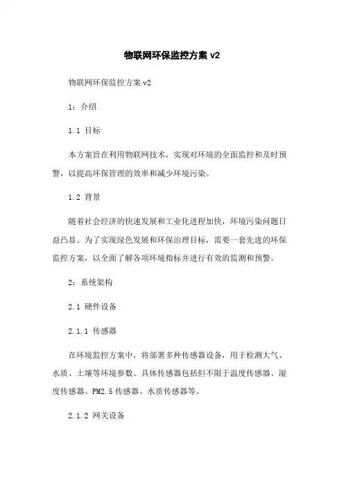
物联网环保监控方案v2物联网环保监控方案v21:介绍1.1 目标本方案旨在利用物联网技术,实现对环境的全面监控和及时预警,以提高环保管理的效率和减少环境污染。
1.2 背景随着社会经济的快速发展和工业化进程加快,环境污染问题日益凸显。
为了实现绿色发展和环保治理目标,需要一套先进的环保监控方案,以全面了解各项环境指标并进行有效的监测和预警。
2:系统架构2.1 硬件设备2.1.1 传感器在环境监控方案中,将部署多种传感器设备,用于检测大气、水质、土壤等环境参数。
具体传感器包括但不限于温度传感器、湿度传感器、PM2.5传感器、水质传感器等。
2.1.2 网关设备为了实现对传感器设备的数据采集和传输,需要部署物联网网关设备。
网关设备负责与传感器通信,并将采集到的数据传输给后端服务器。
2.1.3 服务器后端服务器负责接收并存储传感器采集的环境数据,并进行数据处理和分析。
服务器还负责报表、发送预警信息等功能。
2.2 软件系统2.2.1 数据采集与传输通过物联网网关设备实现对传感器数据的采集和传输。
采集到的数据将通过网络传输到后端服务器。
2.2.2 数据存储与处理后端服务器负责接收传感器数据,并将其存储到数据库中。
服务器还负责对数据进行处理和分析,环境报表等。
2.2.3 预警功能基于采集到的环境数据,后端服务器可以实现预警功能。
当环境指标超过预设阈值时,系统将自动发送预警信息给相关人员。
3:功能需求3.1 数据采集系统需要能够实时采集传感器设备的环境数据,并确保数据的准确性和完整性。
3.2 数据存储与处理系统需要能够将采集到的数据存储到数据库中,并支持数据的查询和分析。
3.3 报表系统需要能够环境报表,用于分析环境状况和评估环境质量。
3.4 预警功能系统需要能够监测环境指标是否超过预设阈值,并在超过阈值时发送预警信息。
4:应用场景4.1 工业区环境监控在工业区域中,部署传感器设备,监测大气污染、水质污染等情况,及时发现和处理异常情况。
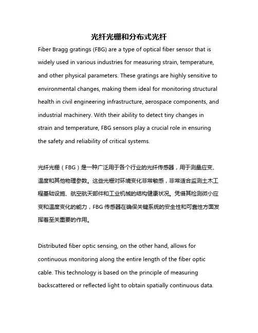
光纤光栅和分布式光纤Fiber Bragg gratings (FBG) are a type of optical fiber sensor that is widely used in various industries for measuring strain, temperature, and other physical parameters. These gratings are highly sensitive to environmental changes, making them ideal for monitoring structural health in civil engineering infrastructure, aerospace components, and industrial machinery. With their ability to detect tiny changes in strain and temperature, FBG sensors play a crucial role in ensuring the safety and reliability of critical systems.光纤光栅(FBG)是一种广泛用于各个行业的光纤传感器,用于测量应变、温度和其他物理参数。
这些光栅对环境变化非常敏感,非常适合监测土木工程基础设施、航空航天部件和工业机械的结构健康状况。
凭借其检测微小应变和温度变化的能力,FBG传感器在确保关键系统的安全性和可靠性方面发挥着至关重要的作用。
Distributed fiber optic sensing, on the other hand, allows for continuous monitoring along the entire length of the fiber optic cable. This technology is based on the principle of measuring backscattered or reflected light to obtain spatially continuous data.Distributed sensing systems are particularly useful for detecting early signs of structural degradation, such as cracks, deformation, or corrosion, in hard-to-reach or hazardous environments.另一方面,分布式光纤传感技术允许沿着整个光纤电缆的长度进行连续监测。

Gasmonitor PlusGasmonitor PlusGas DetectionControl PanelsChoosing the Control Panel for your needsGasmonitor Plus is our flexible microprocessor-controlled system designed with a modularapproach, so you get exactly what you want.Used accross the globe, both on and offshore,Gasmonitor Plus provides the cost-effectivesolution to your system requirements.Fixed systems for gas and fire monitoring Gasmonitor Plus is our flexible microprocessor-controlled systemdesigned with a modular approach, so you get exactly what you want.Used throughout the world, both on and offshore, Gasmonitor Plusprovides the cost-effective solution to your system requirements.Gasmonitor Plus, the gas and fire control system you can trust.Simple to use Gasmonitor Plus offers flexibility while still providing simple operation. All theday to day functions are accessible via push buttons on the front panel.As well as a rolling display, indicating the channel currently monitored,each channel has a bar graph display. This unique bar graph format isranged to indicate readings below the first alarm setting, providing aninstantaneous representation of the gas concentration on every detector.Common alarm LEDs on the display card and individual alarmson the panel only light when a hazard or fault is detected. Thismeans the whole rack status can be checked at a glance.Flexible architecture Each channel has three levels of alarm as well as a dedicatedanalogue output, set as 4-20 mA as standard.Optional relay modules can interface to the panel to provide up to a totalof 84 output relays per rack. Sixteen of these relays can be configured/voted from a combination of the three levels of alarm per channel.The RS232 digital interface provides connectivity with PC for configurationand datalog upload. Each rack is uniquely addressable, making multi-drop architectures possible. This cuts down on configuration.Proven in-use Gasmonitor Plus is a microprocessor-based expandable control system,which can be multiplied to offer unlimited channels and outputs.Its modular construction provides ultimatecustomisation capacity with minimum wiring.Large, clear displayCommon alarm indicators Universal gas input cardsIndividual channel alarm inhibitsUnique bar graph reading per channel Channel alarm indicatorsIndustry-standard gas detectors Remote reset switch Analogue outputs per channel - 4-20mA or 1-5Vdc AC/DC Power options Dedicated external audio/visual alarm drive Optional voted relays Dual channel, with up to 20 smoke/heat detectors per zone Optional battery backup Common and individual channel relays for levels1, 2, 3 and fault with voting relay optionSpecificationSize483 x 133 x 294 mm (19 x 5.25 x 11.5 ins) Weight9.5kg (21lbs)Enclosure material Aluminium alloyMounting Rack mounted (3u format)*Channels16 per rackInputs Gas 2 or 3 wire, 4-20mA (sink or source) or mV bridgeFire - smoke detectors, heat detectors and manual call points, up to 20 per loop Maximum 32 loops per rack (ie 16 twin zone fire modules)Outputs Analogue16 x 4-20mA, max load 960 Ohms or 1-5 V, min. load 100 Ohms External audible/visual alarm drive Powered 24 V dc, max load up to 200mA for each alarm level Relays Type Up to 84 DPCO, contacts rated 5 A @ 250 V ac, non-inductive loadAssignment- common- per channel- voting Relay modes Alarm 1, Alarm 2, Alarm 3, FaultGas alrams 1, 2, & 3, fire & faultUp to 16, configurableEnergised / de-energised & latching, non-latchingDigital communication RS232 with PanelsPro or SetGMon onlyLogging Built-in datalogger - data available via PanelsPro or SetGmonPanel indication Channel numberGas readingMeasurement unitsSystem fault 4 lines x 20 characters back-lit LCDOn main LCD plus green LED bar-graph on channel card ppm, %LEL, %vol, fireyellow LEDAlarm indication Audible-internal sounderVisual- alarm- fault- inhibit As standard3 individual & 3 common alarms (red LED) Individual and common fault (yellow LED) Individual inhibit (yellow LED)Power AC mainsDCBattery back-up 100-260 V ac 50/60 Hz external 27.6 V dcExternalRemote accept/reset As standard Lamp test As standardApprovals Low voltage directiveEMC DirectiveATEX Meets BS EN 61010-1Meets EN 50082-1, EN 50081-1, EN 50270, EN61000-6-4Conforms to EN60079-25 in configuration with Zener Barrier Baseefa 05Y0090/1Operating temperature0°C to +50°C (32°F to 122°F) Humidity0-95% non-condensing。
英文回答:Monitoring of ambient air quality is essential to ensure sustained improvements in public health and the ecological environment. Particle contamination is one of the major factors affecting air quality. We need to develop technical methodological guidelines for the monitoring of ambient air particle resolution to effectively monitor and manage air quality. When developing technical methodological guidance, it is important to take full account of actual monitoring needs and technological advances, to ensure that monitoring results are accurate and reliable and to provide a scientific basis forbating air pollution. The development of technical methodological guidelines requires a thorough study of the current state of relevant technological development and application needs at home and abroad, the monitoring of the actual situation in relation to domestic air quality, and the requirements of laws and regulations and standards to ensure the scientific and practicality of technical methodological guidance.环境空气质量的监测对于保障公众健康和生态环境的持续改善至关重要。

f6智慧门店系统使用设计方案智慧门店系统是一种利用物联网、大数据分析、云计算等技术手段对门店进行数字化管理的系统。
该系统旨在提升门店的运营效率、顾客体验和营销效果。
下面是一个关于f6智慧门店系统的设计方案的简要介绍。
一、系统架构设计:f6智慧门店系统采用分布式架构。
主要包括前端门店终端、中间层应用服务器和后端数据中心三个部分。
前端门店终端部分包括收银系统、POS终端、安全监控系统等,负责数据采集和实时监控。
中间层应用服务器部分负责数据处理、算法运算和业务逻辑实现。
后端数据中心部分负责数据存储、分析和管理。
二、功能设计:1. 实时监控:通过安装摄像头和传感器,实时监控门店内的人流量、货物情况、温湿度等信息。
通过视频分析技术对人员行为进行分析,提醒工作人员处理异常情况。
2. 数据分析:对门店的销售数据、客流数据、库存数据进行收集、存储和分析。
通过数据挖掘和机器学习算法,提供销售预测、库存管理、客户行为分析等功能,帮助门店优化经营决策。
3. 客户管理:通过系统记录顾客的购买历史、喜好等信息,实现精准化营销。
可以通过短信、微信、APP等多种方式与客户进行互动,提供个性化推荐和优惠券等营销手段。
4. 供应链管理:通过系统对供应链进行全面管理,包括采购、配送、库存、质量控制等环节。
实现供需的精确匹配,减少库存积压和缺货现象。
5. 系统集成:与ERP系统、CRM系统、会员系统等进行无缝对接,实现数据共享和业务协同。
提高信息流、物流和资金流的效率和准确性。
三、技术选型:1. 采用大数据平台,如Hadoop、Spark等,实现海量数据的存储和分析。
2. 采用云计算技术,实现系统的弹性扩展、性能优化和成本控制。
3. 采用物联网技术,实现门店终端设备与系统的连接,实现实时数据采集和远程管理。
4. 采用图像分析、自然语言处理和机器学习等技术,实现对门店数据的自动化处理和分析。
四、可行性分析:1. 技术可行性:系统采用成熟的物联网、大数据分析和云计算等技术,具备实施的技术基础。
医院辐射环境监测方案范文英文回答:Hospital Radiation Environment Monitoring Plan.Introduction.Radiation is a natural part of our environment. However, exposure to high levels of radiation can be harmful to human health. Hospitals use a variety of radiation-producing devices, such as X-ray machines, CT scanners, and nuclear medicine cameras. It is important to monitor the radiation environment in hospitals to ensure that patients and staff are not exposed to harmful levels of radiation.Purpose.The purpose of this radiation environment monitoring plan is to:Identify and assess potential sources of radiation exposure in the hospital.Establish a program for monitoring radiation levels.Develop procedures for responding to radiation emergencies.Scope.This plan applies to all areas of the hospital where radiation-producing devices are used.Responsibilities.The Radiation Safety Officer (RSO) is responsible for implementing and overseeing this plan. The RSO will work with the hospital administration, staff, and patients to ensure that the plan is followed.Procedures.Identification and Assessment of Radiation Sources.The RSO will identify and assess all potential sources of radiation exposure in the hospital. This will include a review of the hospital's equipment, procedures, and patient population.Radiation Monitoring Program.The RSO will establish a program for monitoring radiation levels in the hospital. This program will include the use of radiation detectors to measure radiation levels in different areas of the hospital. The RSO will also review the hospital's equipment and procedures to identify any areas where radiation levels may be elevated.Response to Radiation Emergencies.The RSO will develop procedures for responding to radiation emergencies. These procedures will include instructions on how to evacuate the affected area, how to decontaminate personnel and equipment, and how to notifythe appropriate authorities.Training.The RSO will provide training to hospital staff on the risks of radiation exposure and the procedures for responding to radiation emergencies.Recordkeeping.The RSO will maintain records of all radiation monitoring data and radiation emergencies. These records will be used to track radiation levels in the hospital and to evaluate the effectiveness of the radiation environment monitoring plan.Review and Revision.This plan will be reviewed and revised annually by the RSO. The RSO will also review the plan whenever there is a change in the hospital's equipment, procedures, or patient population.中文回答:医院辐射环境监测方案。
A TRANSLATINGboth systems to advanced, practical, mature, reliable, but also to open systems, scalability, and take into account reasonable investment, the purpose of the best efficiency. CCTV surveillance equipment on the spot on surveillance, control and management of these facilities in a safe, reliable and efficient operation, and make full use of intelligent management role, to create a safe, healthy, comfortable and to be able to improve the efficiency of the fine work environment , energy conservation, and reduce maintenance personnel. According to the project's environmental needs, and demand for the establishment of joint function of the item CCTV monitoring,1, the system has the following features:CCTV main task is an important part of the building within the developments, such as dynamic flow conditions macroeconomic surveillance, control, the various anomalies in order to conduct real-time evidence, review, to the timely processing of purpose.1) video signal timing, location switch programming.2) view and record images, and a distinction should be characters time (year, month, day) display.3) receive signal superimposed elevator floor.4) synchronized switching: Power, synchronous or synchronous.5) to receive security subsystems signal system, in accordance with the need to achieve joint control or system integration.6) internal and external communications links.7) security surveillance television system and security alarm system linked, should be able to automatically switch, display, record of the image signal alarm location and alarm time.8) Power ControlCamera security control room should be unified with green power by the security control room operators-to cut off. On the security control room far away from the camera is powered reunification can be difficult to resolve the nearest, if the system is a synchronous mode of power, and security must be the same for the control room of a reliable power supply.2, the system has the following features:H.264 compression technologyH.264 video coding standard is designed for the high-quality image compression campaign designed by the low bit-rate image compression standard. H.264 video coding used in the movement of the common coding method, coding and decoding process is divided into two parts interframe coding. Egypt Intra Improved DCT transformation and quantified in the inter-frame of a 1 / 2 pixel motion vector forecast compensation technology, motion compensation more precise, quantifiable improvements apply variable length coding table (VLC) and quantitative data for entropy coding, coding final coefficient.H.264 standard higher compression ratio, the entire CIF format-mode single occupied bandwidth in the hundreds around the general, occupied bandwidth depending on the specific exercise how many different picture. Deficiency is relatively poor quality of some, occupied bandwidth screen with movement and the complexity of substantial change.In short, this is a closed-circuit television monitor so that the item highly automated, highly efficient elegant comfortable, convenient and speedy, high-security environment of space. System mainly consists of three parts: front-end monitoring; Monitoring Centre (control center); workstation (client).The installation of video surveillance point: Color night vision cameras and color of high illumination cameras and other equipment installed in the designated location, providing 12 VDC power supply and video interface.Monitoring CentreAccording to specific requirements of schools, teaching areas (of nine school buildings), by Information Centre and the Centre set up a control extensions, the clinic, teachers dormitory (a total of two dormitory) and garage, the living quarters of students (total 12 dormitory) to install a control extensions, canteens, supermarkets, sports centre, student activity centre, Training Center, the south gate, Simon and the North have set up a control extensions, in the host control centre set up to monitor the entire campus that in turn control the first time police information and criminals every move in the room were Baoweichu president and the establishment of a control center.DVR control center through the control system can be arbitrary view the full image (to authority), and a monitoring point for the implementation of cloth Chefang, video playback operations (to access).Control centers are located in the President's Office, the leading sub-control center can ca arbitrary control of pan, tilt and zoom images and action. As a management and understanding of the situation both inside and outside the hospital auxiliary means. House leadership not to the office in order to understand the key parts of the hospital situation.Through transmission from the remote video signals through digital hard disk video recorders to provide resource sharing connections. All the video and alarm records can be shared through the network (to access).Set up seven distribution of authority, the operators were in a different authority to operate. System of great security, all users must provide to the user name and password to detect competence, not manipulation system.Alarm system with tips and video motion detection capabilities greatly save disk space, a police video documentary video to be stored, the system does not reach to facilitate enquiries for information after the incident, the police want to delete documents must be carried out by the system administrator .Alarm systems also have automated records and functional linkage, the system interface unit with the police, and other police equipment can be connected. Any time a system of regional security alarms were triggered, the system will automatically switch to alarm the camera screen monitor regional, state and automatically transferred to video. If two or more simultaneous alarm information, the system can simultaneously record or order of the corresponding alarm and regional image. Monitoring Centre Digital HD recorders, DVR installation of server-side software, including database system. All front-end server management and monitoring equipment, and maintenance of the client network connections at the same time, monitoring of all network workstations authorized users to manage all office LAN users can log on to a computer server system, depending on image rights surveillance enquiries, such as video playback. To configure and monitor server drives to the video information will be kept a month's time.Server software installation is complete, the system automatically configures the video data storage path, users may need to use the server-side management software to change configuration, the system supports distributed video storage for large-capacity storage may be provided.Monitoring center can be set up in a monitoring station, monitoring workstation as a system administrator user of the system in equipment and user management, including video data maintenance and management. Workstations can be connected with theprojector system can be used to monitor or demonstration.monitoring workstation (client)Network computer users to install DVR client software, landing by the system administrator to provide legal status and server access rights, can become a monitoring station.Client software, including: system configuration tools, control software, and audio and video playback software enquiries.System configuration tool: video can be set to undertake the lens division, video server settings, among others.Monitoring Software: 1-9 frame to provide the real-time monitoring, Haeundae or ball machine control.Enquiries playback software: According to the lens name, date / time, video and other types of enquiries, and intervals for the results. Monitoring centre is just a computer as a server (under video server configuration corresponding amount of demand for hard disk), can be configured as a workstation monitoring systems management and settings to use, when necessary can be configured a projector and workstations connected to peacetime surveillance or system demonstration.Implementation of the systemThe system of cameras and lenses, Haeundae, protective enclosures, monitors, and other traditional products can basically part of the optional, but it should be used cost-effective products.The system used in high-definition color Huamianbangeqi 16 Huamianbangeqi, automatic image switch selectable switching time, a functional image freeze. Video switch matrix by the Chengdu Branch of the MJ516 video switch matrix, and the ways for its 16-way input, the output of five trade unions Road. It is Chinese characters superimposed clock system uptime enquiries, a powerful built-in functions such as Chinese Character Library. It is critical to provide the relevant agreements for secondary development.The software is to use some of the major video capture card provided by the API function and video switching matrix provided by the communication protocol software and services produced receive software, which is one-way video signals and control signals are two-way. Through LAN control commands can be issued.ConclusionThis paper illustrates how the present technological conditions, assembled into one economical and reliable, and compatible with the advanced monitoring system. This system suited to the local area network (10/100 M) on the real-time transmission of digital video images. Multimedia is a simple monitoring system (including video only). Believe that with computer technology, video technology, control technology, communications technology development, network monitoring will also enjoy broad prospects.An analog-to-digital converterAn analog-to-digital converter(ADC) is used to convert a continuously variable signal to a corresponding digital form which can take any one of a fixed number of possible binary values. If the output of the transducer does not vary continuously, no ADC is necessary. In this case the signal conditioning section must convert the incoming signal to a form which can be connected directly to the next part of the interface, the input/output section of the microcomputer itself.The I/O section converts digital “on/off” voltage signals to a formwhich can be presented to the processor via the system buses. Here the state of each input line, whether it is “on” or “off”, is indicated by a corresponding “1” or “0”. In th e analog inputs which have been converted to digital form, the patterns of ones and zeros in the internal representation will form binary numbers corresponding to the quantity being converted.Feedback ControlThe class of control problems to be examined here is one of considerable engineering interest. We shall consider systems with several inputs, some known as controls because they may be manipulated and others called external disturbances, which are quite unpredictable. For example, in an industrial furnace we may consider the fuel flow, the ambient temperature, and the loading of material into the furnace to be inputs. Of these, the fuel flow is accessible and can readily be controlled, while the latter two are usually unpredictable disturbances.In such situations, one aspect of the control problems is to determine how the controls should be manipulated so as to counteract the effects of the external disturbances on the state of the system. One possible approach to the solution of this problem is to use a continuous measurement of the disturbances, and from this and the known system equations to determine what the control inputs should be as functions of time to give appropriate control of the system state.Digital Interface CircuitsThe signals used within microcomputer circuits are almost always too small to be connected directly to the “outside world” and some kind of interface must be used to translate them to a more appropriate form. The design of section of interface circuits is one of the most important tasks facing the engineer wishing to apply microcomputers. We have seen that in microcomputers information is represented as discrete patterns of bits; this digital form is most useful when the microcomputer is to be connected to equipment which can only be switched on or off, where each bit might represent the state of a switch or actuator.Care must be taken when connecting logic circuits to ensure that their logic levels and current ratings are compatible. The output voltages produced by a logic circuit are normally specified in terms of worst case values when sourcing or sinking the maximum rated currents. Thus Voh is the guaranteed minimum “high” voltage when sourcing the maximum rated “high” output current Ioh, while Vol is the guaranteed minimum “low” output voltage when sinking the maximum rated “low” output current Iol. There are corresponding specification for logic inputs which specify the minimum input voltage which will be recognized as a logic “high” state Vih, and the maximum input voltage which will be regarded as a logic “low” state Vil.For input interface, perhaps the main problem facing the designer isthat of electrical noise. Small noises signals may cause the system to malfunction, while larger amounts of noise can permanently damage it. The designer must be aware of these dangers from the outset. There are many methods to protect interface circuits and microcomputer from various kinds of noise. Following are some example:1. Input and output electrical isolation between the microcomputer system and external devices using an opto-isolator or a transformer.2. Removing high frequency noise pulses by a low-pass filter and Schmitt-trigger.3. Protecting against excessive input voltages using a pair of diodes to power supply reversibly biased in normal direction.For output interface, parameters Voh,Vol,Ioh and Iol of a logic device are usually much to low to allow loads to be connected directly, and in practice an external circuit must be connected to amplify the current and voltage to drive a load. Although several types of semiconductor devices are now available for controlling DC and AC powers up to many kilowatts, there are two basic ways in which a switch can be connected to a load to control it.With series connection, the switch allows current to flow through the load when closed, while with shunt connection closing the switch allows current to bypass the load. Both connections are useful in low-power circuits, but only the series connection can be used in high-power circuits because of the power wasted in the series resistor R..AT89C52Compatible with MCS-51™ Products,8K Bytes of In-System Reprogrammable Flash Memory,Endurance: 1,000 Write/Erase Cycles, Fully Static Operation: 0 Hz to 24 MHz,Three-level Program Memory Lock,256 x 8-bit Internal RAM,32 Programmable I/O Lines,Three 16-bitTimer/Counters, Eight Interrupt Sources, Programmable Serial Channel Low-power Idle and Power-down Modes.DescriptionThe AT89C52 provides the following standard features: 8K bytes of Flash, 256 bytes of RAM, 32 I/O lines, three 16-bit timer/counters, a six-vector two-level interrupt architecture, a full-duplex serial port, on-chip oscillator, and clock circuitry. In addition, the AT89C52 is designed with static logic for operation down to zero frequency and supports two software selectable power saving modes. The Idle Mode stops the CPU while allowing the RAM, timer/counters, serial port, and interrupt system to continue functioning. The Power-down mode saves the RAM contents but freezes the oscillator, disabling all other chip functions until the next hardware reset.AT89C52 Timer 2Timer 2 is a 16-bit Timer/Counter that can operate as either a timer or an event counter. The type of operation is selected by bit C/T2 in theSFR T2CON (shown in Table 2). Timer 2 has three operating modes: capture, auto-reload (up or down counting), and baud rate generator. The modes are selected by bits in T2CON, as shown in Table 3. Timer 2 consists of two 8-bit registers, TH2 and TL2. In the Timer function, the TL2 register is incremented every machine cycle. Since a machine cycle consists of 12 oscillator periods, the count rate is 1/12 of the oscillator frequency. In the Counter function, the register is incremented in response to a 1-to-0 transition at its corresponding external input pin, T2. In this function, the external input is sampled during S5P2 of every machine cycle. When the samples show a high in one cycle and a low in the next cycle, the count is incremented. The new count value appears in the register during S3P1 of the cycle following the one in which the transition was detected. Since two machine cycles (24 oscillator periods) are required to recognize a 1-to-0 transition, the maximum count rate is 1/24 of the oscillator frequency. To ensure that a given level is sampled at least once before it changes, the level should be held for at least one full machine cycle.Capture ModeIn the capture mode, two options are selected by bit EXEN2 in T2CON. If EXEN2 = 0, Timer 2 is a 16-bit timer or counter which upon overflow sets bit TF2 in T2CON. This bit can then be used to generate an interrupt. If EXEN2 = 1, Timer 2 performs the same operation, but a 1- to-0 transition at external input T2EX also causes the current value in TH2 and TL2 to be captured into RCAP2H and RCAP2L, respectively. In addition, the transition at T2EX causes bit EXF2 in T2CON to be set. The EXF2 bit, like TF2, can generate an interrupt. The capture mode is illustrated in Figure Auto-reload (Up or Down Counter)Timer 2 can be programmed to count up or down when configured in its 16-bit auto-reload mode. This feature is invoked by the DCEN (Down Counter Enable) bit located in the SFR T2MOD. Upon reset, the DCEN bit is set to 0 so that timer 2 will default to count up. When DCEN is set, Timer 2 can count up or down, depending on the value of the T2EX pin.Baud Rate GeneratorTimer 2 is selected as the baud rate generator by setting TCLK and/or RCLK in T2CON. Note that the baud rates for transmit and receive can be different if Timer 2 is used for the receiver or transmitter and Timer 1 is used for the other function. Setting RCLK and/or TCLK puts Timer 2 into its baud rate generator mode. The baud rate generator mode is similar to the auto-reload mode, in that a rollover in TH2 causes the Timer 2 registers to be reloaded with the 16-bit value in registers RCAP2H and RCAP2L, which are preset by software. The baud rates in Modes 1 and 3 are determined by Timer 2’s overflow rate according to the following equation.The Timer can be configured for either timer or counter operation. In most applications, it is configured for timer operation (CP/T2 = 0). The timer operation is different for Timer 2 when it is used as a baud rate generator. Normally, as a timer, it increments every machine cycle (at 1/12 the oscillator frequency). As a baud rate generator, however, it increments every state time (at 1/2 the oscillator frequency). The baud rate formula is given below.where (RCAP2H, RCAP2L) is the content of RCAP2H and RCAP2L taken as a 16-bit unsigned integer. Timer 2 as a baud rate generator is shown in Figure 4. This figure is valid only if RCLK or TCLK = 1 in T2CON. Note that a rollover in TH2 does not set TF2 and will not generate an interrupt. Note too, that if EXEN2 is set, a 1-to-0 transition in T2EX will set EXF2 but will not cause a reload from (RCAP2H, RCAP2L) to (TH2, TL2). Thus when Timer 2 is in use as a baud rate generator, T2EX can be used as an extra external interrupt. Note that when Timer 2 is running (TR2 = 1) as a timer in the baud rate generator mode, TH2 or TL2 should not be read from or written to. Under these conditions, the Timer is incremented every state time, and the results of a read or write may not be accurate. The RCAP2 registers may be read but should not be written to, because a write might overlap a reload and cause write and/or reload errors. The timer should be turned off (clear TR2) before accessing the Timer 2 or RCAP2 registers.中文随着电视技术的发展和闭路电视监控系统要求的提高,闭路电视监控系统迅速成长起来。

摘要在如今发展迅速的环境中,建筑能耗问题已引起了各个国家的重视,在我们的生活中对能源的消耗也也渐渐成为了我国的一大重要解决问题。
我国对于建筑能耗的监测和管理的技术也已日趋完善。
本文主要研究如何用PC机对建筑物内的智能仪表进行监控和管理,采用何种通信方式完成计算机与智能仪表之间的通信。
在本设计中主要可以分为上位机和下位机两大部分,上位机的主要任务是利用组态软件进行整个建筑能耗监测管理系统平台的设计,下位机则是利用单片机来模拟我们生活中的智能仪表,最后利用串口通信可以实现上位机对下位机的控制,并且可以提取下位机的数据。
其中的通信用到了RS-485现场总线和Modbus通信协议,这也和现实工业中所应用的能耗监控系统相吻合。
关键词:建筑能耗通信协议RS-485 Modbus 智能仪表AbstractIn this rapid developmental environment, building energy consumption has raised much attention through many countries. Energy consumption has become an essential problem for us to solve not only in industry but also in our daily life. Our technology of monitoring and managing the building energy consumption has been gradually improved.This study focuses on how to use Personal Computer to monitor and manage the intelligent meters in buildings, and using what communication technology to achieve the communication between Personal Computer and intelligent meters. This design can be separated into two parts: Personal Computer and console computer. The former one is mainly used to design the monitoring and management system of building energy consumption. The latter one is designed to imitate the intelligent meters by using MCU. And thus manage the Personal Computer and console computer by using serial communication, and extract the data. RS-485 and Modbus protocols are used in this communication, which is consistent with the applied energy monitoring system in real industry.Key words:Building Energy consumption Protocols RS-485 Modbus Intelligent Meters目录摘要 (I)Abstract ........................................................................................................... I I 引言....................................................................................................... - 1 - 1. 绪论 ....................................................................................................... - 2 - 1.1研究背景及意义 .................................................................................... - 2 - 1.2 国内外发展现状 ................................................................................... - 2 - 1.3 本课题的目的及意义 ............................................................................ - 4 -1.4 本课题研究的主要内容......................................................................... - 4 -2. RS-485现场总线.................................................................................... - 6 - 2.1 RS-485总线......................................................................................... - 6 - 2.2 RS-485总线的特点 .............................................................................. - 6 - 2.3 RS-485总线布线规律........................................................................... - 7 -2.3 RS-485总线布线方法........................................................................... - 8 -3. Modbus通信协议 ................................................................................... - 9 - 3.1 Modbus协议概述 ................................................................................. - 9 - 3.2 Modbus物理层................................................................................... - 10 - 3.3 协议报文............................................................................................ - 11 - 3.4 两种串行传输模式.............................................................................. - 13 - 3.4.1 ASCII模式....................................................................................... - 13 -3.4.2 RTU模式......................................................................................... - 13 - 3.5 差错校验方法..................................................................................... - 14 - 3.5.1 LRC校验......................................................................................... - 14 -3.5.2 CRC校验 ........................................................................................ - 15 -4. 下位机系统设计 ................................................................................... - 17 - 4.1 下位机系统硬件设计 .......................................................................... - 17 - 4.1.1 RS-232转RS-485电路设计 ........................................................... - 18 - 4.1.2 RS-485转TTL电路设计 ................................................................. - 20 -4.2 下位机软件设计 ................................................................................. - 22 -5. 上位机的组态软件设计......................................................................... - 26 - 5.1 ForceControl V7.0 简介 ..................................................................... - 26 - 5.2 建筑能耗监测管理系统的设计............................................................ - 26 - 5.2.1 系统权限管理.................................................................................. - 27 - 5.2.2 能源实时分析.................................................................................. - 30 - 5.2.3 系统安全预警.................................................................................. - 32 - 5.2.4 能耗统计分析.................................................................................. - 33 - 结论..................................................................................................... - 37 - 致谢..................................................................................................... - 38 - 参考文献................................................................................................... - 39 -引言随着我国的经济发展,在我们的生活中涌现出了越来越多的智能化的产品,对能源的消耗也是越来越多,但是能源消耗问题在之前却没能得到大家的重视。
动环监控系统实施方案一、概述。
动环监控系统是指基于物联网技术,对设备、环境等进行实时监控和管理的系统。
在现代工业生产中,动环监控系统的应用已经成为提高生产效率、保障设备安全运行的重要手段。
本文将就动环监控系统的实施方案进行详细介绍,以便于各行各业在实际应用中能够更好地运用该系统。
二、系统设计。
1. 系统架构。
动环监控系统主要包括数据采集、数据传输、数据处理和数据显示等模块。
数据采集模块负责采集设备、环境等数据;数据传输模块将采集的数据传输至数据处理模块;数据处理模块对传输过来的数据进行处理和分析;数据显示模块将处理后的数据以图表、报表等形式展示给用户。
2. 设备选型。
在动环监控系统的实施过程中,需要根据实际监控对象的特点选择合适的监控设备。
比如温度、湿度监控可选用温湿度传感器,电气设备监控可选用电流、电压传感器等。
在选型过程中,需要考虑设备的精度、稳定性、通信方式等因素。
三、系统实施。
1. 网络建设。
动环监控系统需要建设一个稳定可靠的网络环境,以保证数据的及时传输和处理。
在网络建设过程中,需要考虑网络带宽、网络安全、网络稳定性等因素,选择合适的网络设备和网络架构。
2. 系统部署。
系统部署是指将动环监控系统的各个模块部署到相应的位置,并进行联调测试。
在部署过程中,需要考虑设备的布局、传感器的安装位置、数据传输的可靠性等因素,以保证系统能够正常运行。
3. 系统调试。
系统调试是指对已部署的动环监控系统进行功能测试和性能优化。
在调试过程中,需要对数据采集、传输、处理和显示等模块进行全面测试,发现并解决系统中的问题和不足。
四、系统运维。
1. 数据管理。
动环监控系统需要对采集的大量数据进行管理和存储。
在数据管理过程中,需要考虑数据的存储周期、数据的备份和恢复、数据的清理和整理等问题,以保证数据的完整性和可靠性。
2. 系统维护。
系统维护是指对动环监控系统的硬件设备和软件系统进行定期的维护和保养。
在维护过程中,需要对设备进行检查和维修,对软件系统进行更新和升级,以保证系统的稳定和可靠运行。
能源环保设备监控系统的优化设计发布时间:2023-06-30T02:56:48.925Z 来源:《新型城镇化》2023年13期作者:赵收1 王萌2 [导读] 本文中的系统优化首先从工业网络安全问题出发,从根本上保证了系统的安全稳定运行。
1.烟台双塔食品股份有限公司山东烟台 2654002.烟台清敏科技咨询有限公司山东烟台 265400摘要:为提高能源环保设备的运行和管理效率,提升技术经济指标,本设计对自动化监控的方法进行整合,对现有能源环保设备监控技术进行优化,利用物联网监控与能源管理系统深度开发融合,提高生产线的集中监控程度。
关键词:自动化控制;分布式系统;能源环保设备;系统优化;集中监控;本文中的系统优化首先从工业网络安全问题出发,从根本上保证了系统的安全稳定运行。
同时认真考虑了工业数据采集效率问题,保证了实时数据采集点数量尽可能多、数据传输速率尽可能快、数据采集频率尽可能高以及数据处理方式相对合理等方面,利用先进的自动化、信息化技术和网络技术实现能源环保设备的集中监控管理的优化设计,设备运行效率更高、人工成本更低。
1 工业能源管控现状1.1能源应用数字化程度不足。
现有能源计量系统仅包括能源计量数据的曲线监测和部分报表的功能,检测结果还在不同层次系统中,无法进行共享和有效利用。
1.2能源与生产管理协同不足。
工业能源的供给与消费主要为工厂的工业品的生产服务,缺乏多角度、多维度的能源分析,不能指导同类次产品能耗对标。
与生产业务部门协同仅限于线下,协同的程度和实效性不足以满足优化的需求,能源管理被动服务于生产,无法做到全局优化。
(3)能源管理智能化程度不足。
由于缺乏数据和模型支撑,目前能源管理精细化程度不够,仅能做到监视,无法快速有效分析原因,能源优化难度较大。
部分环节智能化程度不够,仅靠人员经验,稳定性难以保障。
同时,缺乏工业产线辅助设备设施,如动力空调、通风机等动力设备与能源监测的融合分析和联动控制,难以精准及时地实现能源优化。
林业有害生物监测预报工作方案范文English Answer:Introduction.Forest pests and diseases are major threats to forest ecosystems, causing significant economic and environmental damage. Effective monitoring and forecasting of these pests and diseases is crucial for timely detection, management, and mitigation. This Forest Pest and Disease Monitoring and Forecasting Work Plan outlines the guidelines and procedures for implementing a comprehensive monitoring and forecasting system for forest pests and diseases.Objectives.The objectives of this work plan are to:Establish a system for early detection and monitoring of forest pests and diseases.Collect, analyze, and interpret data on pest and disease incidence and severity.Develop and disseminate timely forecasts of pest and disease outbreaks.Promote information sharing and collaboration among stakeholders.Scope.This work plan applies to all forest ecosystems within the defined geographic area. It includes monitoring and forecasting of all major forest pests and diseases, including insects, pathogens, and invasive species.Methods.1. Detection and Monitoring.Conduct regular field surveys to detect and monitorpest and disease incidence and severity.Establish permanent monitoring plots to track changesin pest and disease populations over time.Utilize remote sensing and aerial surveys to coverlarge areas and detect early signs of infestation.2. Data Collection and Analysis.Collect data on pest and disease occurrence, abundance, and distribution.Analyze data to identify trends, patterns, andpotential outbreak risks.Develop models to predict pest and disease population dynamics.3. Forecasting.Develop forecasting systems based on historical data,environmental conditions, and ecological models.Issue timely forecasts of pest and disease outbreaks, including predicted severity and timing.Update forecasts regularly as new data becomes available.4. Information Sharing and Collaboration.Establish a central database to store and share pest and disease information.Disseminate forecasts and monitoring data to stakeholders through various channels (e.g., websites, newsletters)。
ToMonitor分布式环境监测系统 设计方案
深圳市华图测控系统有限公司 二OO九年六月 ToMonitor分布式环境监测系统设计方案
HUATO SYSTEM CO., LTD. Page 2 / 15 Pages 目 录 1.方案概述....................................................................................................3 1.1 公司介绍....................................................................................................................................3 1.2 方案与产品简述.........................................................................................................................4 1.3 500-NET记录仪技术指标..........................................................................................................5 1.4应用领域.....................................................................................................................................6 1.5 遵循国家/行业标准....................................................................................................................6 2.系统设计方案.............................................................................................7 2.1 网络拓扑结构.............................................................................................................................7 2.2 ToMonitor实时网络监测软件....................................................................................................8 2.3 方案优点..................................................................................................................................13 附录:TOMONITOR用户列表(节选)........................................................14 ToMonitor分布式环境监测系统设计方案
HUATO SYSTEM CO., LTD. Page 3 / 15 Pages 1.方案概述 1.1 公司介绍 深圳市华图测控系统有限公司(HUATO SYSTEM CO., LTD.)坐落于深圳市宝安区桃花源科技创新园(国家级留学生创业服务中心),由数位原深圳华为公司研发专家与环境工程工业硕士联合创立。公司致力于环境,电气,电信领域的测控系统的研发,销售与服务,是宝安区政府重点扶持的科技型企业。公司创始人有着非常丰富的环境测控领域的产品研发,方案设计,工程施工与售后服务经历,亲自率队完成了华南师范大学生命科学学院,上海复旦大学医学院动物实验室,上海交通大学生命科学学院等国家重点院校/实验室的人工气候室/洁净室的设计,施工等工作。目前,华图公司客户遍布全国,采用ToMonitor监测系统的客户包括九州通药业,国药清平药业,汕头创美药业,阿尔泰药业,南方电网,广东美术馆,华测(CTI,中国最大的第三方计量检测认证机构),中国兵器工业集团,中兴通讯,百事可乐,广州本田,蒙牛集团,执信医疗,SONY中国工厂等等。 ToMonitor分布式环境监测系统设计方案
HUATO SYSTEM CO., LTD. Page 4 / 15 Pages 1.2 方案与产品简述 ToMonitor分布式环境监测系统是华图公司历时数年潜心研发的高可靠性、高精度、用户界面友好的网络环境监测系统,已成为电信、电力、证券、银行及中小型机房设备实现集中监控的基础设备,它具有数据采集点分散,涉及面广,数据类型多,采集精度高,系统稳定可靠等特点。RS-485工业总线因高速率、长距离、低成本、易施工、运行稳定可靠等特点成为很多工业控制系统的首选标准。ToMonitor系统选用RS-485协议,综合考虑现场设备的多样性和复杂性,采用分布式系统架构,数据采集亦采用标准化接口,使得系统的扩充非常方便。 ToMonitor系统中大量采用华图公司自主研发的S500-NET/500-NET/S380-NET温湿度记录仪。S500-NET智能温湿度数据记录仪是农业研究、食品、医药、化工、气象、环保、电子、实验室等领域对多项气候参数,进行监测记录的仪器。该记录仪是华图公司汲取国外同类产品优点并结合我国特点自主设计,可对温湿度及其它气候参数进行记录。采用高精度瑞士原装进口、一体式温湿度数字式传感器,将采样数据保存在记录仪存储器内。并可将采集记录的数据传送给计算机进行处理。记录仪采用高能量锂电池供电,可选配外部电源,体积小巧便于携带,整机功耗非常小。 长期以来传统的温湿度数据记录方式通常采用的是人工记录或普通记录仪用墨水在记录纸上绘制曲线,其体积庞大、精度低、墨水易堵塞、费时费力。后来出现的巡检仪、无纸记录仪也因体积大、成本高,需外接电源,而未能在工业与科研中大量使用。S500-NET记录仪内置有智能芯片,具有12Bit A/D转换、大屏幕LCD显示、智能记录、远距离通讯功能,采用国际知名品牌的传感器、微处理器,可实时显示并自动记录采集到的温湿度数据,将其保存在记录仪内的非易失存储器中。记录容量达到67551组,按每十分钟记录一次计算可记录约一年半的温湿度数据资料,这是传统检测仪表所不能做到的。 S500-NET记录仪具有多种记录方式及任意的记录间隔设置,为保证仪器对环境适应性与工作的可靠性记录仪不设任何的开关与按钮,所有的设置与开停机均通过通讯接口由一般计算机上运行应用程序的软面板上进行设置。记录仪可脱开计算机独立工作。当需要读取数据时可通过通讯接口由计算机读取记录仪内的数据。 ToMonitor分布式环境监测系统设计方案
HUATO SYSTEM CO., LTD. Page 5 / 15 Pages 1.3 S500-NET记录仪技术指标
精度:温度 ±0.2℃~0.5℃ 湿度 ±2%RH~5%RH 记录容量: 45000组 电池寿命:单机版一年(10秒刷新间隔) ToMonitor分布式环境监测系统设计方案
HUATO SYSTEM CO., LTD. Page 6 / 15 Pages 1.4应用领域 n 实验室监测 n 电力配网监测、电力负荷监控 n 水文监测、水库数据采集、供水自动化 n 油田监控系统 n 城市路灯监控等市政工程 n 铁路数据采集 n 热网与气网监控 n 矿山生产的监测 n 测绘勘探 n 物流管理 n 气象监测 n 仓库管理 n 环保监测 n 工业自动化、无线抄表 n 各种报警系统等领域。
1.5 遵循国家/行业标准 ToMonitor监测系统设计参照以下标准: GBJ73-84 GBJ19-87 JB/T6823-93 JBJ71-90 GB50243-2002 GB50303-2002 ToMonitor分布式环境监测系统设计方案
HUATO SYSTEM CO., LTD. Page 7 / 15 Pages 2.系统设计方案 2.1 网络拓扑结构 ToMonitor监测方案采用TCP/IP与工业总线(RS485)混合组网,技术成熟,可靠性高,经济可行。组网模式采用Client/Server架构,坚持分布式星型布点,集中监控的原则,使单点故障互不影响,测试数据能真实反映室内(箱内)情况,统一监控和独立测控相结合,这样大大提高了系统的可靠性。以本项目项目为例,网络拓扑简图如下:
ToMonitor监测系统包括用户层,控制层,设备层三个部分。能方便连接到用户单位信息管理系统,同时ToMonitor系统内部管理非常方便,全程自动化控制,数据准确,节省人力物力,充分满足自动化温湿度环境监测要求。 上述方案对监测点的分布做了假设,后面需要根据实际情况进行修改。ToMonitor服务器端包括ToMonitor平台软件,协议转换,数据记录与采集三个部分。本方案针对重要设备间环境的实际情况设计,综合运用了先进的环境测量技术、单片机技术、工控软件技术、传感器技术等技术,具有稳定可靠,使用方便,功能先进、扩展性强、易于维护等突出优点。