
and [9] provide the notation and terminology for this paper.
- 格式:pdf
- 大小:172.95 KB
- 文档页数:6
![and [9] provide the notation and terminology for this paper.](https://imgs-1438308264.cos.ap-hongkong.myqcloud.com/b2cc570fba1aa8114431d918.webp)
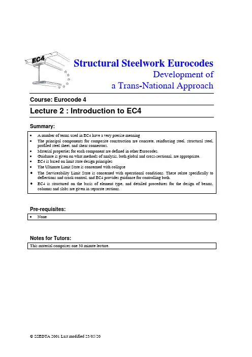
Structural Steelwork EurocodesDevelopment ofa Trans-National Approach Course: Eurocode 4Lecture 2 : Introduction to EC4Summary:Pre-requisites:Notes for Tutors:Objectives:References:Contents:1. Structure of Eurocode 4 Part 1.1The arrangement of sections within EC4-1-1 is based on a typical design sequence, starting withbasic data on material properties and safety factors, then considering issues related to methodsof analysis, before detailing the requirements for element design (at both ultimate and serviceability limit states).EC4 is organised into a number of Sections as follows:Section 1 GeneralOutlines the scope of EC4, defines specific terms, and provides a notation list.Section 2 Basis of DesignOutlines design principles and introduces partial safety factorsSection 3 MaterialsSpecifies characteristic strengths for concrete, steel (reinforcing and structural), and shear connectorsSection 4 DurabilitySpecifies particular requirements for corrosion protection of composite elements, in relation tothe interface between steel and concrete, and galvanising standards for profiled steel sheets for composite slabs.Section 5 Structural AnalysisThis outlines appropriate methods of global analysis and their potential application, and definesthe effective width and section classification.Section 6 Ultimate limit statesThis provides detailed rules regarding detailed sizing of individual structural elements (beamsand columns), including shear connectors. The design of composite slabs is covered in Section9.Section 7 Serviceability limit statesSets out limits on deflections and requirements to control crackingSection 8 Composite joints in frames for buildingsProvides detailed procedures for designing joints.Section 9 Composite slabs with profiled steel sheeting for buildingsProvides specific guidance for the use of composite decking, and sets out detailed proceduresfor verification at both ultimate and serviceability limit states for both shuttering and the composite slab.Section 10 ExecutionProvides guidance on the site construction process. This specifies minimum standards of workmanship as implicitly assumed in the rest of EC4.Section 11 Standard testsDescribes procedures for testing shear connectors and composite floor slabs where standarddesign data is not available.2. Terminologycl. 1.4.2 The Eurocodes define a number of terms which, although often used generally in a rather looseway, have more precise meanings in the context of EC4. These terms are clearly defined andinclude the following:‘Composite member’ refers to a structural member with components of concrete and structural or cold-formed steel, interconnected.by shear connection to limit relative slip.∙‘Shear connection’ refers to t he interconnection between steel and concrete components enabling them to be designed as a single member.∙‘Composite beam’ is a composite member subject mainly to bending.∙‘Composite column’ is a composite member subject mainly to compression or combin ed compression and bending.∙‘Composite slab’ is a slab in which profiled steel sheets act as permanent shuttering and subsequently act to provide tensile reinforcement to the concrete.∙‘Execution’ refers to the activity of creating a building, includin g both site work and fabrication.∙‘Type of building’ refers to its intended function (eg a dwelling house, industrial building)∙‘Form of structure’ describes the generic nature of structural elements (eg. beam, arch) or overall system (eg. Suspension bridge)∙‘Type of construction’ indicates the principal structural material (eg. steel construction)∙‘Method of construction’ describes how the construction is to be carried out (eg prefabricated)∙‘Composite frame’ is a framed structure in which some or all of the elements are composite.∙‘Composite joint’ is a joint between composite members in which reinforcement is intended to contribute to its resistance and stiffness.∙Type of framing:Simple joints do not resist momentsContinuous joints assumed to be rigidSemi-continuous connection characteristics need explicit consideration in analysis∙‘Propped structure or member’ is one in which the weight of concrete applied to the steel elements is carried independently, or the steel is supported in the span, until the concrete isable to resist stress.∙‘Unpropped structure or member’ is one in which the weight of concrete is applied to the steel elements which are unsupported in the span..3. Notation/SymbolsA complete list of symbols is included in EC4. The most common of these are listed below: cl. 1.6 Symbols of a general nature:L, l Length; span; system lengthN Number of shear connectors; axial forceR Resistance; reactionS Internal forces & moments; stiffnessδDeflection; steel contribution ratioλSlenderness ratioχ Reduction factor for bucklingγ Partial safety factorSymbols relating to cross-section properties:A Areab Widthd Depth; diameterh Heighti Radius of gyrationI Second moment of areaW Section modulusDiameter of a reinforcing barMember axesThe following convention is adopted for member axes:x-x along the length of the membery-y axis of the cross-section parallel to the flanges (major axis)z-z axis of the cross-section perpendicular to the flanges (minoraxis)Symbols relating to material properties:E Modulus of elasticityf Strengthn Modular ratioEC4 also makes extensive use of subscripts. These can be used to clarify the precise meaning ofa symbol. Some common subscripts are as follows:c Compression, composite cross-section, concreted Designel Elastick CharacteristicLT Lateral-torsionalpl PlasticNormal symbols may also be used as subscripts, for example:Rd Design resistanceSd Design values of internal force or momentSubscripts can be arranged in sequence as necessary, separated by a decimal point –for example:N pl.Rd Design plastic axial resistance.4. Material properties4.1 Concretecl. 3.1 Properties for both normal weight and lightweight concrete shall be determined according toEC2, but EC4 does not cover concrete grades less than C20/25 or greater than C60/75.4.2 Reinforcing steelProperties for reinforcing steel shall be determined according to EC2, but EC4 does not cover reinforcement grades with a characteristic strength greater than 550N/mm2..cl. 3.24.3 Structural steelProperties for structural steel shall be determined according to EC3, but EC4 does not coversteel grades with a characteristic strength greater than 460N/mm2..cl. 3.34.4 Profiled steel sheeting for composite slabsProperties for steel sheeting shall be determined according to EC3, but EC4 also restricts thetype of steel to those specified in certain ENs.cl. 3.4The recommended minimum (bare) thickness of steel is 0,7mm4.5 Shear connectorsReference is made to various ENs for the specification of materials for connectors. cl. 3.5 5. Structural analysisGeneral guidance is given on what methods of analysis are suitable for different circumstances. cl. 5.1.2 5.1 Ultimate Limit StateFor the Ultimate Limit State, both elastic and plastic global analysis may be used, althoughcertain conditions apply to the use of plastic analysis.When using elastic analysis the stages of construction may need to be considered. The stiffnessof the concrete may be based on the uncracked condition for braced structure. In other cases,some account may need to be taken of concrete cracking by using a reduced stiffness over a designated length of beam. The effect of creep is accounted for by using appropriate values forthe modular ratio, but shrinkage and temperature effects may be ignored.cl. 5.1.4 Some redistribution of elastic bending moments is allowed.Rigid-plastic global analysis is allowed for non-sway frames, and for unbraced frames of two storeys or less, with some restrictions on cross-sections. Cl. 5.1.5 Cl. 5.3.4A similar distinction is made between sway and non-sway frames, and between braced and unbraced frames as for steel frames, and reference is made to EC3 for definitions.5.2 Properties and classification of cross-sectionsThe effective width of the concrete flange of the composite beam is defined, although more rigorous methods of analysis are admitted.cl. 5.2 Cross-sections are classified in a similar manner to EC3 for non-composite steel sections. cl. 5.3 5.3 Serviceability Limit StateElastic analysis must be used for the serviceability limit state. The effective width is as definedfor the ultimate limit state, and appropriate allowances may be made for concrete cracking,creep and shrinkage.cl. 5.46. Ultimate Limit State cl. 6 The ultimate limit state is concerned with the resistance of the structure to collapse. This isgenerally checked by considering the strength of individual elements subject to forcesdetermined from a suitable analysis. In addition the overall stability of the structure must be checked.The ultimate limit state is examined under factored load conditions. In general, the effects on individual structural elements will be determined by analysis, and each element then treated asan isolated component for design. Details of individual design checks depend on the type ofmember (eg beam, column) and are described in other parts of this course.The ultimate limit state design for composite connections and composite slabs are dealt with in Sections 8 and 9 respectively.6.1 Beamscl. 6.3 For beams, guidance is given on the applicability of plastic, non-linear and elastic analysis for determining the bending resistance of the cross-section, with full or partial interaction.Procedures for calculating the vertical shear resistance, including the effects of shear bucklingand combined bending and shear.Beams with concrete infill between the flanges enclosing the web are defined as partiallycl. 6.4 encased, and separate considerations apply to the design for bending and shear for these.cl. 6.5 In general, the top flange of the steel beam in composite construction is laterally restrainedagainst buckling by the concrete slab. However, in the hogging bending zones of continuousbeams, the compression flange is not restrained in this way, and procedures for checking lateral-torsional buckling for such cases are given. If a continuous composite beam satisfies certain conditions defined in EC4, such checks are unnecessary.cl. 6.7 Detailed procedures are given for the design of the longitudinal shear connection, including the requirements for the slab and transverse reinforcement. A range of different connector types is considered.6.2 ColumnsVarious types of composite columns, including encased sections and concrete-filled tubes, arecl. 6.8 covered. Simplified procedures are given for columns of doubly symmetrical cross-section anduniform throughout their length. Guidance is given on the need for shear connection and howthis can be achieved.7. Serviceability Limit StateServiceability requirements are specified in relation to limiting deflections and concretecl. 7.1 cracking. Other less common serviceability conditions relating to control of vibrations andlimiting stresses are not included in EC4.7.1 Deflectionscl. 7.2 At the serviceability limit state, the calculated deflection of a member or of a structure is seldom meaningful in itself since the design assumptions are rarely realised. This is because, for example:∙the actual load may be quite unlike the assumed design load;∙beams are seldom "simply supported" or "fixed" and in reality a beam is usually in some intermediate condition;The calculated deflection can, however, provide an index of the stiffness of a member or structure, i.e. to assess whether adequate provision is made in relation to the limit state of deflection or local damage. Guidance is given on calculating deflections for composite beams, including allowances for partial interaction and concrete cracking. No guidance is given regarding simplified approaches based on limiting span/depth ratios.No reference is given to limiting values for deflections in EC4. It is therefore recommended that calculated deflections should be compared with specified maximum values in Eurocode 3, which tabulates limiting vertical deflections for beams in six categories as follows: EC3 Table 4.1∙roofs generally.∙roofs frequently carrying personnel other than for maintenance.∙floors generally.∙floors and roofs supporting plaster or other brittle finish or non-flexible partitions.∙floors supporting columns (unless the deflection has been included in the global analysis for the ultimate limit state).∙situations in which the deflection can impair the appearance of the building.The deflections due to loading applied to the steel member alone, for example those during the construction stage for unpropped conditions, should be based on the procedures of EC3 usingthe bare steel section properties.Deflections due to subsequent loading should be calculated using elastic analysis of thecomposite cross-section with a suitable transformed section. Where necessary, methods ofallowing for incomplete interaction and cracking of concrete are given7.2 Concrete CrackingConcrete in composite elements is subject to cracking for a number of reasons including direct loading and shrinkage. Excessive cracking of the concrete can affect durability and appearance,or otherwise impair the proper functioning of the building. In many cases these may not becritical issues, and simplified approaches based on minimum reinforcement ratios and maximumbar spacing or diameters can be adopted. Where special conditions apply, for example in thecase of members subject to sever exposure conditions, EC4 provides guidance on calculatingcrack widths due to applied loads. Limiting crack widths are specified in relation to exposure conditions.cl. 7.38. Composite Joints cl. 8 The guidance given applies principally to moment-resisting beam-column connections. It relatesto moment resistance, rotational stiffness, and rotation capacity. The inter-dependence of global analysis and connection design is described, but where the effects of joint behaviour on the distribution of internal forces and moments are small, they may be neglected. Guidance is givenon joint classification as rigid, nominally pinned, or semi-rigid for stiffness, and as full strength, nominally pinned or partial strength in relation to moment resistance.Detailed guidance is given in relation to design and detailing of the joint, including slab reinforcement.9. Composite Slabs cl. 9 Detailed guidance is given in relation to the design of composite slabs, for both ultimate and serviceability limit states. This includes construction stages when the steel sheeting is acting as permanent shuttering and, in an unpropped condition, must resist the applied actions due to wet concrete and construction loads. In this case reference is made to EC3 Part 1.3.Calculation procedures are given for determining the resistance of composite slabs in relation to flexure, longitudinal shear and vertical shear. Principles for determining stiffness for calculating deflections are stated, and conditions in which detailed calculations can be omitted are specifiedin relation to span:depth ratios.。

高等数学教材翻译英文Mathematical Analysis: Advanced Calculus Textbook TranslationAbstract:In this paper, we will discuss the process of translating a high-level mathematics textbook from Chinese to English. The main focus will be on translating various mathematical concepts, equations, and proofs accurately while maintaining a clear and coherent writing style. Additionally, attention will be given to organizing the translated content in a logical and visually appealing manner.1. Introduction:Mathematics is a universal language that transcends cultural and geographical boundaries. As such, it is crucial to provide accurate translations of mathematics textbooks to facilitate the exchange of knowledge across different linguistic communities. This paper aims to outline the key considerations and strategies involved in translating a high-level mathematics textbook, with a focus on advanced calculus.2. Translating Mathematical Concepts:When translating mathematical concepts from Chinese to English, it is important to convey the precise meaning while considering the linguistic differences between the two languages. This involves selecting appropriate mathematical terms, symbols, and notations that are commonly understood in the English-speaking mathematical community. Additionally, effortsshould be made to ensure consistency in terminology usage throughout the translated textbook.3. Translating Equations and Formulas:Equations and formulas play a central role in mathematics, and translating them accurately is of utmost importance. In the translation process, it is necessary to pay attention to the syntax, grammar, and semantics of mathematical expressions. The translator should strive to maintain the original meaning, while adapting the structure and notation tofit the conventions of the English language. Clear and concise explanations should accompany each equation or formula to enhance understanding for English-speaking readers.4. Translating Proofs and Theorems:In advanced calculus textbooks, proofs and theorems are fundamental components that demonstrate mathematical concepts and promote logical reasoning. Translating proofs effectively requires not only an understanding of the mathematical content, but also the ability to convey the step-by-step reasoning in a clear and concise manner. Using appropriate mathematical terminology and logical connectors is crucial to ensure the coherence and effectiveness of the translated proofs.5. Organizing Translated Content:To enhance readability, the translated textbook should be well-organized. Each chapter should have a clear structure, with sections and subsections that logically present the content. Within each section, a coherent flow of ideas should be maintained. The integration of mathematical illustrationsand diagrams can further support comprehension for English-speaking readers. Tables, charts, and graphs should also be included whenever necessary, but care should be taken to ensure that all visual elements are properly labeled and explained.6. Conclusion:Translating a high-level mathematics textbook, particularly in the field of advanced calculus, requires thorough understanding of both the mathematical concepts and the linguistic nuances of Chinese and English. Accurate translation of mathematical content, equations, proofs, and theorems is essential in delivering a comprehensible textbook to English-speaking readers. Furthermore, organizing the translated content in a logical and visually appealing manner enhances the overall readability and accessibility of the textbook. By following these considerations and strategies, a successful translation of a high-quality mathematics textbook can be achieved.。

