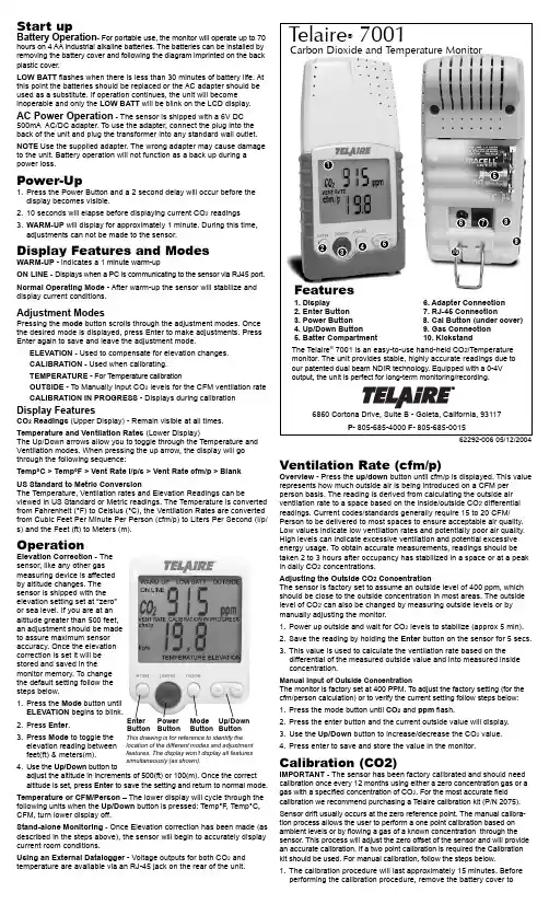
Start upBattery Operation- For portable use, the monitor will operate up to 70hours on 4 AA industrial alkaline batteries. The batteries can be installed by removing the battery cover and following the diagram imprinted on the back plastic cover.LOW BATT flashes when there is less than 30 minutes of battery life. At this point the batteries should be replaced or the AC adapter should be used as a substitute. If operation continues, the unit will become inoperable and only the LOW BATT will be blink on the LCD display. AC Power Operation - The sensor is shipped with a 6V DC500mA AC/DC adapter. To use the adapter, connect the plug into the back of the unit and plug the transformer into any standard wall outlet. NOTE Use the supplied adapter. The wrong adapter may cause damage to the unit. Battery operation will not function as a back up during a power loss.Power-Up1.Press the Power Button and a 2 second delay will occur before thedisplay becomes visible.2.10 seconds will elapse before displaying current CO2 readings3.WARM-UP will display for approximately 1 minute. During this time,adjustments can not be made to the sensor.Display Features and ModesWARM-UP - indicates a 1 minute warm-upON LINE - Displays when a PC is communicating to the sensor via RJ45 port. Normal Operating Mode - After warm-up the sensor will stabilize and display current conditions.Adjustment ModesPressing the mode button scrolls through the adjustment modes. Once the desired mode is displayed, press Enter to make adjustments. Press Enter again to save and leave the adjustment mode.ELEVATION - Used to compensate for elevation changes.CALIBRATION - Used when calibrating.TEMPERATURE - For T emperature calibrationOUTSIDE - To Manually input CO2 levels for the CFM ventilation rate CALIBRATION IN PROGRESS - Displays during calibration Display FeaturesCO2 Readings (Upper Display) - Remain visible at all times. Temperature and Ventilation Rates (Lower Display)The Up/Down arrows allow you to toggle through the Temperature and Ventilation modes. When pressing the up arrow, the display will go through the following sequence:Temp°C > Temp°F > Vent Rate l/p/s > Vent Rate cfm/p > BlankUS Standard to Metric ConversionThe Temperature, Ventilation rates and Elevation Readings can be viewed in US Standard or Metric readings. The Temperature is converted from Fahrenheit (°F) to Celsius (°C), the Ventilation Rates are converted from Cubic Feet Per Minute Per Person (cfm/p) to Liters Per Second (l/p/ s) and the Feet (ft) to Meters (m).OperationElevation Correction - Thesensor, like any other gasmeasuring device is affectedby altitude changes. Thesensor is shipped with theelevation setting set at “zero”or sea level. If you are at analtitude greater than 500 feet,an adjustment should be madeto assure maximum sensoraccuracy. Once the elevationcorrection is set it will bestored and saved in themonitor memory. To changethe default setting follow thesteps below.1.Press the Mode button untilELEVATION begins to blink.2.Press Enter.3.Press Mode to toggle theelevation reading betweenfeet(ft) & meters(m).e the Up/Down button toadjust the altitude in increments of 500(ft) or 100(m). Once the correct altitude is set, press Enter to save the setting and return to normal mode. Temperature or CFM/Person – The lower display will cycle through the following units when the Up/Down button is pressed: Temp°F, Temp°C, CFM, turn lower display off.Stand-alone Monitoring - Once Elevation correction has been made (as described in the steps above), the sensor will begin to accurately display current room conditions.Using an External Datalogger - Voltage outputs for both CO2 and temperature are available via an RJ-45 jack on the rear of the unit.Ventilation Rate (cfm/p)Overview - Press the up/down button until cfm/p is displayed. This valuerepresents how much outside air is being introduced on a CFM perperson basis. The reading is derived from calculating the outside airventilation rate to a space based on the inside/outside CO2 differentialreadings. Current codes/standards generally require 15 to 20 CFM/Person to be delivered to most spaces to ensure acceptable air quality.Low values indicate low ventilation rates and potentially poor air quality.High levels can indicate excessive ventilation and potential excessiveenergy usage. To obtain accurate measurements, readings should betaken 2 to 3 hours after occupancy has stabilized in a space or at a peakin daily CO2 concentrations.Adjusting the Outside CO2 ConcentrationThe sensor is factory set to assume an outside level of 400 ppm, whichshould be close to the outside concentration in most areas. The outsidelevel of CO2 can also be changed by measuring outside levels or bymanually adjusting the monitor.1.Power up outside and wait for CO2 levels to stabilize (approx 5 min).2.Save the reading by holding the Enter button on the sensor for 5 secs.3.This value is used to calculate the ventilation rate based on thedifferential of the measured outside value and into measured insideconcentration.Manual Input of Outside ConcentrationThe monitor is factory set at 400 PPM. To adjust the factory setting (for thecfm/person calculation) or to verify the current setting follow steps below:1.Press the mode button until CO2 and ppm flash.2.Press the enter button and the current outside value will display.e the Up/Down button to increase/decrease the CO2 value.4.Press enter to save and store the value in the monitor.Calibration (CO2)IMPORTANT - The sensor has been factory calibrated and should needcalibration once every 12 months using either a zero concentration gas or agas with a specified concentration of CO2. For the most accurate fieldcalibration we recommend purchasing a T elaire calibration kit (P/N 2075).Sensor drift usually occurs at the zero reference point. The manual calibra-tion process allows the user to perform a one point calibration based onambient levels or by flowing a gas of a known concentration through thesensor. This process will adjust the zero offset of the sensor and will providean accurate calibration. If a two point calibration is required the Calibrationkit should be used. For manual calibration, follow the steps below.1.The calibration procedure will last approximately 15 minutes. Beforeperforming the calibration procedure, remove the battery cover to EnterButtonPowerButtonModeButtonUp/DownButtonThis drawing is for reference to identify thelocation of the different modes and adjustmentfeatures. The display won’t display all featuressimultaneously (as shown).access the calibration activation switch. Connect the supplied AC adapter to the back of the sensor or ensure new batteries are installed.2.Power up the sensor and wait for the Warm-up to end.3.Next verify the Elevation correction has been set. Refer to the steps inElevation Correction for procedure.4.If you are calibrating to ambient conditions make sure the sensor isdisplaying a stable reading - avoid breathing in the area of the monitor.If you are flowing gas to the calibration port of the sensor, allow the gas to flow for at least 10 minutes before initiating calibration.5.Press the Mode button twice. The Calibration mode will begin blinking.5.Press Enter.e the Up/Down button to adjust reading to the current ambientconditions or concentration of the gas being used. Pressing the button once will change the readings in increments of 10 ppm. To increase the speed, press and hold the button.NOTE - For best accuracy, a reference or known concentration of CO2 should be used when adjusting the reading. Bottled nitrogen can be used to provide a zero concentration gas.7.Next, on the backside of the unit locate the push button switch (underthe battery cover, in the small round hole to the right of the connector jack), use a small pointed object to depress and hold the switch for 5 seconds. CALIBRATION will begin to blink.8.Press Enter.9.Calibration In Progress will begin to blink. At this point the unit willprogram itself based on the CO2 value that was input in Step 6. The calibration process will take approximately 5 minutes.When Calibration is complete, the display will return to the steady Calibration mode. Press Enter to return to the normal operation mode. Temperature AdjustmentUse this procedure to adjust the temperature output when you wish to have the temperature output match a reference sensor. The accuracy of a field adjustment is dependent upon the stability of the environment is which the procedure is performed, and upon the accuracy of the refer-ence sensor.1.Connect the supplied AC adapter to the back of the sensor. If you donot have the AC adapter, new batteries should be used.2.Power up the sensor and place in a stable environment, free of draftsor temperature changes. Wait 30 minutes for the unit to fully equili-brate with the environment. Do not hold the unit in your hand during this period. Press the mode button until the blinking word TEMPERA-TURE appears.4.Press Enter. Both the word TEMPERATURE and the numerictemperature display will begin blinking in unison.e the Up/Down button to adjust the temperature reading to matchthe reference.6.Press Enter. The temperature offset is immediately adjusted, theblinking stops, and the unit is now in normal operating mode. AccessoriesCO2View™ Real-Time Graphing/Calibration Software 2080Allows the 7001 to log directly to a Windows™ compatible PC and graph concentrations in real time (includes RS232 cable). Includes an interface that allows the user to perform a zero and span calibration on the sensor. Hobo® Data-Logger Kit CO2 – Temp & RH 2077Small data-logger that mounts to the back of the 7001. Records CO2, Temp, and Relative Humidity. Stores over 7900 data points and samples at a user adjustable time interval. Graphing software included.2070 Datalogging CableConnects the 7001 to 3rd party devices. Includes two leads for the CO2 and temperature ouputs.Calibration Kit 2075Comes with necessary equipment to perform zero calibration.SpecificationsMethodDual Beam Absorption Infrared™Display - LCDIndependent CO2 and Temperature readings.Calculates and Displays Ventilation RatesSample MethodDiffusion or flow through (50 - 100 ml/min)Performance - CO2 ChannelMeasurement Range0-10,000 ppm display0-4,000 ppm voltage outputDisplay Resolution± 1 ppmAccuracy±50 ppm or ±5% of reading up to 5,000 PPM (Above 5,000 PPM not specified)Repeatability±20 ppmTemperature Dependence±0.1% of reading per °C or ±2 ppm per °C, whichever is greater, refer-enced to 25°CPressure Dependence:0.13% of reading per mm Hg (Corrected via user input for elevation) Response Time<60 seconds for 90% of step changeWarm-Up Time<60 seconds at 22°CCalibration Interval12 months, offset adjustment using single gas at 0-1000 ppm CO2. Full factory calibration availablePerformance - Temperature ChannelTemperature RangeVoltage output32 to 104°F (0 to 40°C)Display32 to 122°F (0 to 50°C)Display Resolution0.1°F (0.1°C)Display Options°F, °C, or Off. Set with panel button.Accuracy±2°F (±1°C)Response Time20-30 minutes (case must equilibrate with environment)Calibration Interval12 months, offset adjustment using temperature standard at 50 to 86°F (10 to 30°C). Full factory calibration availableOutputs(Analog) CO20-4 VDC, 1mV/ppm (4,000 ppm max)Temperature0-4 VDC linear, 32-104°F (0-40°C)Output Impedance100 Ohms(Digital)RS232 for use with Telaire® CO2View™ Graphing Software(Wiring Connection)One RJ-45 ConnectorDual Analog output plus digital outputPower SupplyBattery TypeFour AA batteries, not includedBattery Operation80 hours (alkaline)External6 VDC from external AC/DC adapter, includedPower Requirements100 mA Peak, 20 mA average from 6VGeneralOperating Conditions32-122°F (0-50°C)0-95% RH, non-condensingStorage Temperatures-4 to 140°F (-20 to 60°C)CertificationsFCC Class 15 Part BCEWarranty18 months parts and laborThis product is covered by one or more of the following patents:5,650,624 / 5,721,430 / 5,444,249 / 5,747,808 / 5,834,777 / 5,163,332 /5,340,986 / 5,502,308 / 6,344,798 / 6,023,069 / 5,370,114 / 5,601,079 /5,691,704 / 5,767,776 / 5,966,077 / 6,107,925 / 5,798,700 / 5,945,924 /5,592,147 / 6,255,653 / 6,250,133 / 6,285,290WarrantyThis Telaire product has been examined and tested for proper operation. Pleaseoperate this product only in accordance with the instructions.Telaire warrants this product against defects in workmanship and materials for aperiod of 18 months from the date of purchase by the original owner. If the productshould become defective within this warranty period we will repair or exchange it.A return authorization number must be obtained from the factory prior to returningequipment. Items received without a return authorization number will be refused.Product to be serviced under this warranty should be sent to T elaire, 6860 Cortona Dr,Suite B, Goleta, CA 93117. Shipment must be prepaid, properly packed and insured.Telaire is not and will not be liable for any consequential loss or damages thatmay occur by reason of purchase and use of this product. The responsibility ofTelaire, in any event, is strictly limited to the replacement/repair of the product.Telaire seeks to present reliable information concerning the composition,properties and use of its products, however; (1) All advice concerning selectionand use of any product is provided at no charge and with no warranty. (2) Nowarranty is made hereby. Products described herein are warranted to conform toTelaire specifications only at the time of sale. All sales are subject to Telairestandard terms and conditions, which are reproduced on the reverse side of eachinvoice. All warranties of merchantability and fitness of purpose are disclaimedand remedy for any breach of warranty is limited to replacement of the defectiveproduct. (3) Telaire assumes no responsibility for any patent liability arising fromthe use of any product in a process, manner or formula not designed by Telaire.P/N 62292-00605/12/2004。