无线温度传感器
- 格式:doc
- 大小:162.00 KB
- 文档页数:22

IWTT SeriesIndustrial Wireless Temperature TransmitterWhilst every effort has been taken to ensure the accuracy of this document, we accept no responsibility for damage, injury, loss or expense resulting from errors or omissions, and reserve the right of amendment without notice.This document may not be reproduced in any way without the prior written permission ofthe company.Issue 2 September 2018Cynergy3 Components Ltd7 Cobham Road, Ferndown Ind Estate, WimborneDorset BH21 7PE, United KingdonTel:+44(0)1202897969,email:******************CONTENTS1. INTRODUCTION _______________________________________________________ 3 1.1 Safety Information _________________________________________________________ 31.2 Hardware Features ________________________________________________________ 32. UNPACKING __________________________________________________________ 33. PRODUCT IDENTIFICATION LABEL _____________________________________ 45. SETTING UP THE IWTT WIRELESS TEMPERATURE TRANSMITTER _______ 56. TROUBLE-SHOOTING GUIDE __________________________________________ 67. SYSTEM PART NUMBERS______________________________________________ 78. SPECIFICATIONS______________________________________________________ 81. INTRODUCTION1.1 Safety InformationThis manual contains information that must be observed in the interest of your own safety and to avoid damage to assets. Please read this manual before installing and commissioning the device and keep the manual in an accessible location for all users.To satisfy FCC RF Exposure requirements for mobile and base station transmission devices, a separation distance of 20cm or more should be maintained between the antenna of this device and persons during operation. To ensure compliance operation at closer than this distance is not recommended. The antenna used for this transmitter must not be co-located or operating in conjunction with any other antenna or transmitter.1.2 Hardware FeaturesThe IWTT range of Wireless Temperature Transmitters has been designed to measure the Temperature of the medium connected and transmit the value to one of the IWR range of receivers where the value can be outputted as either a 4-20mA or 1-5Vdc signal.The IWR-1 has a single output and the IWR-5 has five outputs, each of which can be linked to an IWTT transmitter.The IWTT temperature transmitter works on the licence-free 2.4 GHz band.Ranges of up to 500m are possible using the standard transmitter and receiver unit with the optional 3dBi antenna giving a range of up to 750m.The transmitter is powered by a 3.6V lithium cell and care must be taken to insert the battery in the correct polarity.2. UNPACKINGThe instrument should be carefully inspected for signs of damage which may have occurred in transit. In the unlikely case that damage has been sustained, DO NOT use the instrument, but please retain all packaging for our inspection and contact your supplier immediately.3. PRODUCT IDENTIFICATION LABELThe unit delivered should be carefully inspected to ensure it is suitable for the application required. Detailed information on the product is included in the identification label and the user manual.Please ensure in particular, that the temperature range of the IWTT is suitable for the intended application and that the IWTT unit will not be subjected to temperatures and/or temperatures greater than those specified in this manual.4. INSTALLING/CHANGING THE BATTERYA Lithium 3.6V battery is included inside the IWTT transmitter. The battery may be changed at any time but the correct polarity must be observed at all times! After the battery has been changed, the unit should be switched on using SW3 pushbutton and then SW1 should be pushed for 5s.This is to ensure the battery life count is reset correctly when a new battery is installed.The internal LED will flash 5 times to indicate this procedure has been carried out successfully.The battery life is determined by the rate the transmitter sends the Temperature value to the receiver, this update rate can be selected using Dip Switch 1 and the default value is 10s.Please dispose of all batteries as specified by the legislator according to the Closed Substance Cycle and Waste Management Act or country regulations.5. SETTING UP THE IWTT WIRELESS TEMPERATURE TRANSMITTERThe IWTT instrument is shipped in a default configuration which allows the unit to connect with any default IWR receiver unit and transmit the measured temperature every10s simply by switching the unit on using SW3 on the internal circuit board.If a different update rate is required, or a different network frequency channel is required these parameters can be selected using DIP Switch 1 as detailed below:Switches 1, 2, 3 & 4 select the RF Network the IWTT will transmit on. The defaultnetwork for both the IWTT transmitter and IWR receiver is network 1.RF NETWORK 1 2 3 41 0 0 0 02 0 0 0 13 0 0 1 04 0 0 1 15 0 1 0 06 0 1 0 17 0 1 1 08 0 1 1 19 1 0 0 010 1 0 0 111 1 0 1 012 1 0 1 113 1 1 0 014 1 1 0 115 1 1 1 016 1 1 1 1Switches 5, 6 & 7 select the Transmission rate of the unit. This effectively sets how oftenthe temperature value is sent to the receiver.Transmit time 5 6 710 seconds 0 0 020 seconds 0 0 130 seconds 0 1 060 seconds 0 1 1120 seconds 1 0 0600 seconds 1 0 11 second 1 1 05 seconds 1 1 1Switches 8, 9 and 10 set the Channel Number of the transmitter. This is used with the 5 channel receiver unit (IWR-5) to select which Temperature transmitter is linked to which 4-20mA or 1-5Vdc output channel.Tx Channel Number 8 9 101 0 0 02 0 0 13 0 1 04 0 1 15 1 0 0The IWTT transmitter is now set up and ready to be used. Install the unit into the pipework as required and switch the unit ON using SW3. Pushbutton switch SW1 can be pushed to force the unit to transmit its current temperature and LED 1 will flash twice if the transmission has been received and acknowledged by an IWR receiver unit.If the unit has transmitted successfully the 4-20mA or 1-5Vdc output of the connected receiver unit will output a value reflecting the temperature level being measured.6. TROUBLE-SHOOTINGGUIDEProblem encountered Possible CausesLED1 doesn’t flash when pushbutton SW1 is pressed Unit not switched on, switch on using SW3. Battery not installed correctly.Battery needs replacing.LED1 only flashes once when SW1 is pressed IWR receiver not switched on.IWR receiver not set up for the same RF network.IWR receiver not within range of transmitter.If IWR-1 receiver is used, ensure that the transmitter is set to Tx Channel 1Output from IWR receiver isn’t equivalent to the Temperature being monitored IWR receiver set up incorrectly, see IWR user manual for further details.Check that the green external LED on the receiver is flashing when the transmitter pushbutton is pressed as receiver may be out of range.7. SYSTEM PART NUMBERSPart Number Temperature Range Probe TypeIWTTP100A -200 - +800 PT100 100mm ¼” BSPIWTTP150A-200 - +800 PT100150mm ¼” BSPIWTTP200A-200 - +800 PT100200mm ¼” BSPIWTTP250A-200 - +800 PT100250mm ¼” BSPIWTTP300A-200 - +800 PT100300mm ¼” BSPIWTTP400A-200 - +800 PT100400mm ¼” BSPIWTTJ200A0- 1200 J Type t/c200mm ¼” BSPIWTTJ300A0- 1200 J Type t/c300mm ¼” BSPIWTTJ400A0- 1200 J Type t/c400mm ¼” BSPIWTTK150A0- 1200 K Type t/c150mm ¼” BSPIWTTK200A0- 1200 K Type t/c200mm ¼” BSPIWTTK300A0- 1200 K Type t/c300mm ¼” BSPIWTTK400A0- 1200 K Type t/c400mm ¼” BSPIWTTUP100A -200 - +800 PT100 100mm ¼” NPTIWTTUP150A-200 - +800 PT100150mm ¼” NPTIWTTUP200A-200 - +800 PT100200mm ¼” NPTIWTTUP250A-200 - +800 PT100250mm ¼” NPTIWTTUP300A-200 - +800 PT100300mm ¼” NPTIWTTUP400A-200 - +800 PT100400mm ¼” NPTIWTTUJ200A0- 1200 J Type t/c200mm ¼” NPTIWTTUJ300A0- 1200 J Type t/c300mm ¼” NPTIWTTUJ400A0- 1200 J Type t/c400mm ¼” NPTIWTTUK150A0- 1200 K Type t/c150mm ¼” NPTIWTTUK200A0- 1200 K Type t/c200mm ¼” NPTIWTTUK300A0- 1200 K Type t/c300mm ¼” NPTIWTTUK400A0- 1200 K Type t/c400mm ¼” NPTPart Number Number of Output ChannelsIWR-1 OneIWR-5 FiveIANT-3 3 dBi Antenna8. SPECIFICATIONSSystem PerformanceAccuracy (non-linearity & hysteresis) <±0. 5 °CSetting Errors Zero & Full Scale,<±0.5°CThermal Zero Shift <±0.04% / FS / °CThermal Span Shift <±0.02% / °C typicalMedia Temperature -200 to +1200 °C (depending on sensor type)Ambient Temperature -20 to +80 °CStorage Temperature -20 to +80 °CTemperature Probe Stainless SteelO Ring Seals VitonProbe type Mineral InsulatedEnclosure Material AcetalWeight 310gRF Transmitter Contains FCC W70MRF24J40MDMEPower Requirements Lithium Ion C 3.6V CellBattery Life 5 Years (10s transmission rate)Dimensions 132-432mm x 79 x 52mm (L x W x D)(length depends on sensor ordered)Orientation Mounting Any。
无线测温装置的原理和应用引言无线测温装置是一种用于无线监测温度的智能设备,它具有许多应用领域,如工业生产、环境监测、医疗保健等。
本文将介绍无线测温装置的原理和应用。
原理无线测温装置的工作原理基于以下几个关键技术:1.温度传感器:无线测温装置采用高精度的温度传感器,如热电阻或热电偶。
这些传感器能够将温度转换为电信号。
2.无线通信模块:无线测温装置内置无线通信模块,例如Wi-Fi、蓝牙或Zigbee等。
通过无线通信模块,装置可以将采集到的温度数据传输到远程设备。
3.微控制器单元:无线测温装置中集成了微控制器单元,该单元负责管理温度传感器和无线通信模块之间的数据交换和处理。
4.电源管理:无线测温装置通常使用电池或充电电池供电,并通过电源管理模块实现电源的管理和优化,以延长装置的使用寿命。
应用无线测温装置在以下领域中有广泛的应用:1. 工业生产•温度监测:无线测温装置可用于实时监测工业设备的温度,帮助预测设备故障和维护需求,提高生产效率和设备寿命。
•温度控制:通过与温度控制系统集成,无线测温装置可实现自动控制工艺参数,确保工业生产过程中的温度稳定性。
2. 环境监测•水质监测:无线测温装置可用于实时监测水体的温度,帮助监测水质变化,提供预警和保护环境。
•大气监测:无线测温装置可安装在气象台、气象探测器等设备上,实时监测大气温度,用于天气预报和气候研究。
3. 医疗保健•体温监测:无线测温装置可用于监测病人的体温变化,对于疾病的监控和治疗非常重要。
此外,该装置还可用于监测婴儿的体温,提供智能化的婴儿护理服务。
•热能管理:通过监测人体周围的温度变化,无线测温装置可以提供个性化的热能管理,帮助人们增强身体适应能力和舒适度。
结论无线测温装置通过温度传感器、无线通信模块、微控制器单元和电源管理等关键技术,实现了对温度的实时监测和远程传输。
它在工业生产、环境监测和医疗保健等领域中都有广泛的应用。
随着物联网技术的不断发展,无线测温装置将进一步提升其性能和应用范围,为我们的生活带来更多便利。
无线温度计原理及应用无线温度计是一种能够通过无线通信技术实时监测和传输温度信息的设备。
它采用了无线传感器网络技术,由多个无线传感器节点组成,并通过主节点与其他设备进行通信。
无线温度计的原理是通过传感器将物体的温度转化为电信号,然后利用无线通信技术将电信号传输给主节点,再由主节点进行数据处理和传输。
无线温度计的传感器节点通常由温度传感器、微处理器、无线收发器和电池等组成。
温度传感器是无线温度计的核心部件,其工作原理基于利用温度敏感材料的温度-电压或温度-电阻特性来测量温度。
当温度发生变化时,其温度-电压或温度-电阻特性也随之发生变化,从而使得传感器输出的电信号发生变化。
微处理器负责接收、处理和储存传感器输出的电信号,并将其转化为可供无线收发器发送的数据。
无线收发器则负责将处理后的数据通过无线通信技术发送给主节点,实现温度数据的传输。
电池则为传感器节点提供电源,保障其正常工作。
无线温度计的应用非常广泛。
首先,在生活中的应用方面,无线温度计可以应用于家居温度监测,通过无线传感器节点布置在不同房间中,可以实时监测各个房间的温度,并且可以通过手机APP等设备查看和控制室内温度。
此外,无线温度计还可以应用于冷链物流监测,通过布设无线传感器节点在物流箱或货物上,可以实时监测货物的温度,以确保货物在运输过程中的温度符合要求。
其次,在工业领域的应用方面,无线温度计可以应用于石油、化工、电力等行业,在这些行业中温度监测非常重要。
例如,在石油钻探中,无线温度计可以用于监测井口温度,帮助工人判断井口是否存在高温风险。
在化工中,无线温度计可以用于监测反应釜内的温度,确保反应的正常进行。
在电力行业中,无线温度计可以用于监测发电机组的温度,及时发现和解决设备故障。
此外,无线温度计还可以应用于生物医学领域。
医院中的无线温度计可以用于监测病区的温度,帮助医护人员及时调节病区的温度,提供更加舒适的环境。
同时,无线温度计还可以应用于体温监测,通过将无线传感器节点嵌入体温计中,可以实现无接触、长时间监测患者的体温变化。
无线温度传感器的设计摘要:随着社会的进步和生产的需要,利用无线通信进行温度数据采集的方式已经渗透到社会生活生产的每一个角落,温度测量的准确度在影响生产效益的同时也在逐步得到社会的重视。
关健词:无线温度传感器设计在工业现场,由于生产环境恶劣,工作人员不能长时间停留在现场观察设备是否运行正常,就需要采集数据并传输数据到一个环境相对好的操控室内,工作人员可以在这里将控制指令传输给现场执行模块进行各种操作。
这样就会产生数据传输问题,由于厂房大、需要传输数据多,使用传统的有线数据传输方式就需要铺设很多很长的通讯线,浪费资源,占用空间,可操作性差,出现错误换线困难。
此时便需要利用无线传输的方式进行数据采集。
在农业生产上,不论是温室大棚的温度监测,还是粮仓的管理,无线通信技术的发展使得温度采集测量精确,简便易行。
为此,采用以下方案设计一种无线温度传感器,能够方便人们的工作和生产。
1、传感器的选择传统的模拟式传感器具有测量转换速度快,温度测量范围宽的优点。
但是模拟传感器的模拟信号需要先经过取样、放大和模数转换电路处理,再将转换得到的表示温湿度值的数字信号交由微处理器或 dsp 处理。
被测信号从敏感元件接收的非电物理量开始,到转换为微处理器可处理的数字信号之间,设计者须考虑的线路环节较多。
采用具有直接数字量输出的传感器能够避免上述问题。
数字式传感器能把被测模拟量直接换成数字量输出,可以直接与数字设备(计算机,计数器,数字显示系统等)相联,数字式传感器具有高的测量精度和分辨率,稳定性好,信号易于处理、传送和自动控制,便于动态及多路测量,读数直观,安装方便,维护简单,工作可靠性高。
考虑系统的经济性和温湿度传感器的优缺点及发展状况,确定温度传感器采用数字式。
2、短距离无线通信模块的选择随着大规模集成电路技术的发展,世界上主要的芯片厂商都推出了无线收发芯片。
短距离无线通信系统的大部分功能都集成到一块芯片内部,一般使用单片数字信号射频收发芯片,加上微控制器和少量外围器件构成专用或通用无线通信模块。
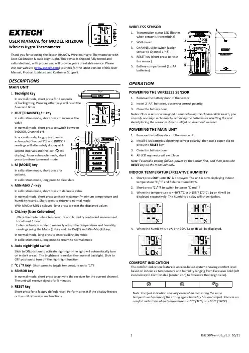
Wireless Hygro-ThermometerThank you for selecting the Extech RH200W Wireless Hygro-Thermometer with User-Calibration & Auto Night Light. This device is shipped fully tested and calibrated and, with proper use, will provide years of reliable service. Please visit our website ( ) to check for the latest version of this User Manual, Product Updates, and Customer Support.DESCRIPTIONSMAIN UNIT1. Backlight keyIn normal mode, short press for 5 secondsof backlighting. Pressing other keys will reset the 5-second timer2. OUT (CHANNEL) / + keyIn calibration mode, short press to increase the valueIn normal mode, short press to switch between INDOOR, Channel 1~8In normal mode, long press to enter auto-cycle (Channel 1~8 and INDOOR readings will alternately display at 4-second intervals and the icon will display). From auto-cycle mode, short press to return to normal mode. 3. M (MODE) keyIn calibration mode, short press for options.In calibration mode, long press to clear data 4. MIN-MAX / - keyIn calibration mode, short press to decrease valueIn normal mode, short press to check maximum/minimum temperature and humidity records. Short press to return to normal modeWith MAX or MIN displayed, long press to reset the displayed values 5. CAL key (User Calibration)Place the meter into a temperature and humidity controlled environment for at least 1 hour.Enter calibration mode to manually adjust the temperature and humidity readings using the Mode (3) key and the Out(2) and Min-Max(4) keys. In normal mode, long press to enter calibration mode In calibration mode, long press to return to normal mode 6. Auto night-light switchSlide to ON position to activate night-light (the light will automatically turn on in dark areas). The brightness is weaker than normal backlight. Slide to OFF position to turn off the night-light function7. °C / °F key - Short press to toggle temperature units °C/°F 8. SENSOR keyIn normal mode, short press to activate the receiver for the current channel. The unit will receive signals for 5 minutes 9. RESET keyShort press for a factory default reset. Perform a reset if the display freezes or the unit otherwise malfunctions.WIRELESS SENSOR1. Transmission status LED (flasheswhen sensor is transmitting) 2. Wall mount3. CHANNEL slide switch (assignsensor to Channel 1 ~ 8) 4. RESET key (short press to resetthe sensor) 5. Battery compartment (2 x AAbatteries)OPERATIONPOWERING THE WIRELESS SENSOR1. Remove the battery door of the sensor2. Insert 2 ‘AA ’ batteries, observing correct polarity3. Close the battery doorNotes: Once a sensor is assigned a channel using the channel slide switch, you can only re-assign a channel by removing the batteries or resetting the unit. Avoid placing the sensor in direct sunlight or inclement weather.POWERING THE MAIN UNIT1. Remove the battery door of the main unit2. Install 4 AA batteries observing correct polarity; then use a paper clip topress the RESET key 3. Close the battery door 4. All LCD segments will switch onNote: To avoid a pairing failure, power up the sensor first, and then press the RESET key on the main unit only.INDOOR TEMPERATURE/RELATIVE HUMIDITY1. Short press OUT until ‘IN ’ is displayed. The unit is now displaying indoortemperature °C / °F and Relative Humidity %. 2. Short press °C / °F to switch between °C and °F3. When the temperature is <-40°F/°C or > 158°F (70°C), Lo or HI will bedisplayed respectively. The humidity display will show dashes.4. When the humidity is < 1% or > 99%, Lo or HI will be displayed.COMFORT INDICATIONThe comfort indication feature is an icon-based system showing comfort level based on indoor air temperature and humidity ranging from Excessive Cold (left icon below) to Comfortable (center icon) to Excessive Heat (right icon).Note: Comfort indication can vary even when measuring the sametemperature because of the strong effect humidity has on comfort. There is no comfort indication when temperature is < 0°C (32°F) or > 60°C (140°F).TEMPERATURE AND HUMIDITY TRENDING ARROWSThe temperature and humidity trend indicator illustrates the temperature and humidity change over time. Arrows indicate rising (left icon shown below), steady (center icon), or falling temperatures (right icon).MAX/MIN RECORDINGView the MAX/MIN temperature and humidity readings since the last reset. 1. In normal mode, short press MIN-MAX to show the current maximumtemperature and humidity values (diagram on left below); press again to show the minimum values (diagram in center); press again to exit the mode (the unit automatically exits the mode after approximately 5 seconds). 2. Perform a manual reset (clear MAX/MIN readings) by long pressing MIN-MAX when the unit is displaying the MAX/MIN records (diagram on right).RECEIVING WIRELESS SENSOR SIGNALS1. In normal mode, short press SENSOR to start receiving data.2. The signal icon will flash (diagram on left below) until reception occurs.After 5 minutes, the icon will disappear if reception fails (center diagram). 3. Receiving a wireless signal after a manual reset or when SENSOR is pressedwill cause dashes to display in the readings area when waiting for signal. 4. For successful reception, the signal icon will appear as shown in thediagram below on right. The selected channel number appears in the box below the icon.5. In normal mode, short press OUT to switch the display between INDOOR and CHANNEL 1~8.6.In normal mode, long press OUT to toggle auto-cycle mode ON/OFF. Auto-cycle alternately displays the channels at 4-second intervals (the icon will show when auto-cycle is active). In auto-cycle mode only the actively communicating channels will appear. Short press OUT to exit mode.7.To check the signals from multiple wireless sensors, short press OUT repeatedly in normal mode.Indoor Channel 1 Channel 58.If the signal for Channel 1~8 is lost and does not recover within 1 hour, the signal icon will disappear. The temperature and humidity will display “Er” for the corresponding channel.9.If the signal does not recover within 48 hours, replace the batteries of the “Er” chann el’s sensor and then press SENSOR on the main unit to pair with the sensors for each “Er” channel again.Note To initiate reception after installing new batteries in the wireless sensor, press SENSOR ; otherwise, the main unit will fail to receiv e the sensor’s signal.LOW TEMPERATURE ICONWhen the outdoor temperature is 37.4°F (3.0°C) or below, the low temperature icon ‘LO’ flashes on the display.LOW BATTERY CONDITIONIf the main unit or the sensor batteries are low, the low battery icon will display. The icon will only appear when the corresponding channel is displayed. For example, if the CHANNEL 1 sensor battery is low, the icon will show only when CHANNEL 1 is displayed. Replace the batteries by following instructions in sections Powering the Wireless Sensor and Powering the Main Unit .TEMPERATURE/HUMIDITY CALIBRATION1. In normal mode, long press the CAL key to enter the calibration mode. Thecurrent outdoor channel o r “IN” (indoor) icon will flash. Short press OUT to choose Indoor (IN) or a Channel number 1~8.2. Short pressM (MODE) to step through the temperature calibration,humidity calibration, and channel selection modes. 3. In temperature calibration mode, use the [ + ] [ - ] keys to adjust the valuein 0.1° steps. Long press to scroll quickly.4. In humidity calibration mode, use the [ + ] [ - ] keys to adjust the displayedvalue in 1% steps. Long press to scroll quickly.5. Long press M at the temperature or humidity calibration screens to revertto the previous calibration value for the selected channel. 6. To exit calibration mode, long press CAL or wait 60 seconds for the unit toexit and return to the normal mode automatically. 7. If the reading for the selected channel is showing either dashes (flashing) orthe HI /Lo indicators, adjustment will not be possible; return unit for service. Note: Comfort indication is a calculation based on calibrated temperature and humidity measurements.IMPORTANT NOTESAttention! Please dispose of batteries and unit in an ecologically safe manner. Always place the unit away from interfering sources such as monitors,computers, appliances, and other devices. Avoid placing the unit on, or next to, metal plates or surfacesFCC STATEMENTThis device complies with Part 15 of the FCC Rules. Operation is subject to the following two conditions: (1) this device may not cause harmful interference, and (2) this device must accept any interference received, including interference that may cause undesired operation.Warning: Changes or modifications to this unit not expressly approved by the party responsible for compliance cou ld void the user’s authority to operate the equipment.NOTE: This equipment has been tested and found to comply with the limits for a Class B digital device, pursuant to Part 15 of the FCC Rules. These limits are designed to provide reasonable protection against harmful interference in a residential installation. This equipment generates, uses and can radiate radio frequency energy and, if not installed and used in accordance with the instructions, may cause harmful interference to radio communications.However, there is no guarantee that interference will not occur in a particular installation. If this equipment does cause harmful interference to radio or television reception, which can be determined by turning the equipment off and on, the user is encouraged to try to correct the interference by one or more of the following measures:-Reorient or relocate the receiving antenna.-Increase the separation between the equipment and receiver.-Connect the equipment into an outlet on a circuit different from that to which the receiver is connected.-Consult the dealer or an experienced radio/TV technician for help.This device complies with Industry Canada License-exempt RSS-210. Operation is subject to the following two conditions: (1) this device may not cause interference, and (2) this device must accept any interference, including interference that may cause undesired operation of the device.FCC Responsible party:Company Name: FLIR Commercial Systems, Inc.Address: 9 Townsend West, Nashua NH 03063 USAPhone: 1- 603-324-7842IC ID: 1590A-RH200WT; FCC ID: IWK-RH200W-T; CAN RSS-Gen/CNR-Gen.SPECIFICATIONSMAIN UNITIndoor temperature range/resolution: -5°C ~ 50°C (23°F ~ 122°F) / 0.1°C/°F Temperature Accuracy: ±2°C (3.6°F), < 0°C (< 32°F)±1°C (1.8°F), 0~40°C (32~104°F)±2°C (3.6°F), > 40°C (> 104°F)Humidity range/resolution: 1% ~ 99 % / 1%Humidity Accuracy (at 25°C [77°F]): ±8%RH (20~39% RH); ±5%RH (40~70% RH)±8%RH (71~90% RH)Power: 1.5V AA X 4 (alkaline battery recommended) Dimensions: 130 (W) x 112 (H) x 27.5 (D) mm (5.1 x 4.4 x 1.1 in.) Weight: 295g (0.65 lbs.)WIRELESS SENSOROutdoor temperature range: -40°C ~ 60°C (-40°F ~140°F)Outdoor humidity range: 1% ~ 99 %Temperature resolution: 0.1°C/°FRelative humidity resolution: 1%Accuracy: See accuracy specs for Main Unit aboveWireless sensor signal frequency: 433MHzNo. of remote sensors: Eight (8) units max.RF transmission range: 30m (98.4 ft.) maximumPower: 1.5V AA X 2 batteries (alkaline recommended) Dimensions: 61 (W) x 113.6 (H) x 39.5 (D) mm (2.4 x 4.5 x 1.5 in.) Weight: 136g (0.3 lbs.) Two-year WarrantyTeledyne FLIR LLC warrants this Extech brand instrument to be free of defects in parts and workmanship for two years from date of shipment (a six-month limited warranty applies to sensors and cables). To view the full warranty text please visit: /support/warranties.Calibration and Repair ServicesTeledyne FLIR LLC offers calibration and repair services for the Extech brand products we sell. We offer NIST traceable calibration for most of our products. Contact us for information on calibration and repair availability, refer to the contact information below. Annual calibrations should be performed to verify meter performance and accuracy. Product specifications are subject to change without notice. Please visit our website for the most up-to-date product information: .Contact Customer SupportCustomer Support Telephone List: https:///contact Calibration, Repair, and Returns: *****************Technical Support: https://Copyright © 2021 Teledyne FLIR LLCAll rights reserved including the right of reproduction in whole or in part in anyform。
无线测温:详细介绍一下无源无线测温什么是无源无线测温?无源无线测温是一种通过无线传输技术,实现非接触式测温的方式。
与传统的有源式无线测温不同,无源无线测温不需要配备电池或外部电源,可以通过接收到的无线信号来获取目标物体的温度信息。
在无源无线测温技术中,关键的部件是温度传感器。
温度传感器通常由两个不同的金属材料制成,称之为热偶。
当热偶的一个端口与目标物体接触时,热偶会产生微小的电压差异,这个电压差异与目标物体的温度成正比。
通过使用无线能量传输技术,将能量传输给微控制器和无线传输芯片,这些芯片通过无线信号传输目标物体的温度数据。
无源无线测温的优势相比传统的测温方式,无源无线测温有以下几个优势:非接触式测温无源无线测温不需要接触目标物体,无论是不规则形状还是高温表面,都能够准确的测量物体的温度,避免了传统测温设备因为接触不良、测点不准确、误差大等问题所带来的不便和不稳定。
实时、快速测温无源无线测温能够实现实时测温,同时由于不需要待测物体处于静止状态,完全可以在物体运动的过程中实时测量,从而提供更精准、快速的测温数据,并且不会对被测试的物体产生任何干扰。
性价比高相比传统的测温设备,无源无线测温不需要配备电池或外部电源,而且无须布线,省去了大量的费用和时间,因此更加节约成本,而且可以快速实现部署。
此外,无源无线测温还可以实现对多个点进行测温,因此更具有性价比。
安全稳定性高无源无线测温采用非接触式测温方式,与物体不产生实际的接触,避免了传统测温设备潜在的安全风险,而且无源无线测温的传感器可以通过无线信号传输数据,因此不会给使用者带来任何干扰或损害,保证了设备的稳定性。
总结无源无线测温是一种前沿的测温技术,它可以实现实时、非接触、高稳定性的测温,而且操作简单、成本低,非常适合于各种需要测温的应用场景。
尽管无源无线测温目前还存在一些技术问题,但是这种技术已经发展成为了许多现代制造业、工业环境、医疗领域和生活领域应用的主流技术,可谓是当今科技创新的重要成果。
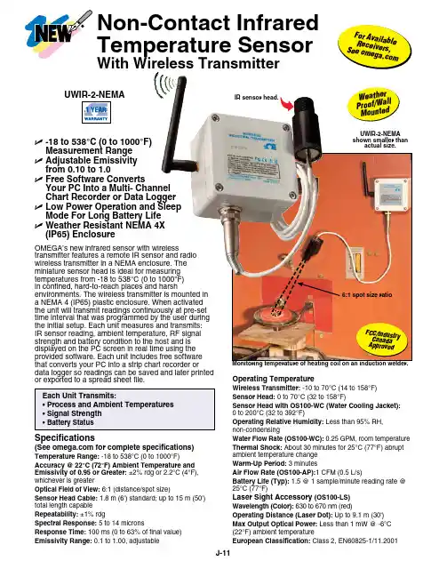
OMEGA’s new infrared sensor with wirelesstransmitter features a remote IR sensor and radio wireless transmitter in a NEMA enclosure. The miniature sensor head is ideal for measuring temperatures from -18 to 538°C (0 to 1000°F) in confined, hard-to-reach places and harshenvironments. The wireless transmitter is mounted in a NEMA 4 (IP65) plastic enclosure. When activated the unit will transmit readings continuously at pre-set time interval that was programmed by the user during the initial setup. Each unit measures and transmits: IR sensor reading, ambient temperature, RF signal strength and battery condition to the host and is displayed on the PC screen in real time using the provided software. Each unit includes free software that converts your PC into a strip chart recorder ordata logger so readings can be saved and later printed or exported to a spread sheet file.Operating TemperatureWireless Transmitter: -10 to 70°C (14 to 158°F)Sensor Head: 0 to 70°C (32 to 158°F)Sensor Head with OS100-WC (Water Cooling Jacket): 0 to 200°C (32 to 392°F)Operating Relative Humidity: Less than 95% RH, non-condensingWater Flow Rate (OS100-WC): 0.25 GPM, room temperature Thermal Shock: About 30 minutes for 25°C (77°F) abrupt ambient temperature change Warm-Up Period: 3 minutesAir Flow Rate (OS100-AP):1 CFM (0.5 L/s)Battery Life (Typ): 1.5 @ 1 sample/minute reading rate @ 25°C (77°F)Laser Sight Accessory (OS100-LS)Wavelength (Color): 630 to 670 nm (red)Operating Distance (Laser Dot): Up to 9.1 m (30')Max Output Optical Power: Less than 1 mW @ -6°C (22°F) ambient temperatureEuropean Classification: Class 2, EN60825-1/11.2001Specifications(See for complete specifications)Temperature Range: -18 to 538°C (0 to 1000°F)Accuracy @ 22°C (72°F) Ambient Temperature and Emissivity of 0.95 or Greater: ±2% rdg or 2.2°C (4°F), whichever is greaterOptical Field of View: 6:1 (distance/spot size)Sensor Head Cable: 1.8 m (6') standard; up to 15 m (50') total length capable Repeatability: ±1% rdgSpectral Response: 5 to 14 micronsResponse Time: 100 ms (0 to 63% of final value)Emissivity Range: 0.1 to 1.00, adjustableU -18 to 538°C (0 to 1000°F) Measurement Range U A djustable Emissivity from 0.10 to 1.0U F ree Software ConvertsYour PC Into a Multi- Channel Chart Recorder or Data Logger U L ow Power Operation and Sleep Mode For Long Battery Life U W eather Resistant NEMA 4X (IP65) EnclosureF C C /I n d u str y C a n a d a A p p r o v e dF o r A v ai l a b l e R e c e i v er s , S e e o me g a .c o mUWIR-2-NEMA shown smaller thanactual size.IR sensor head.W e a t h e rP r o o f /W al lM o u n t ed Non-Contact Infrared Temperature SensorWith Wireless Transmitter6:1 spot size ratioOS100-AP air purge collar to keep the lens free of particles or debris.Both shown smallerthan actual size.Maximum Operating Current: 45 mA @ 3 VdcFDA Classification: Complies with 21 CFR 1040.10, Class II laser product Beam Diameter: 5 mm (0.20")Beam Divergence: <2 mradOperating Temperature: 0 to 50°C (32 to 122°F)Operating Relative Humidity: Less than 95% RH, non-condensingbattery assembly.Ordering Examples: UWIR-2-NEMA, wireless infrared transmitter, UWTC-REC1, 48-channel USB receiver, UWTC-BATT-C, spare battery, and OS100-MB, sensor head bracket.UWIR-2-NEMA, wireless infrared transmitter, UWTC-REC2-D-MA, 48-channel transceiver/host with 1-channel 4 to 20 mA analog output, alarm and local display, UWTC-BATT-C, spare battery, and OS100-MB, sensor head bracket. OCW-3, OMEGACARE SM extends standard 1-yearwarranty to a total of 4 years.Power:(1.5 x 2")LASER RADIATION - DO NOT STARE INTO BEAM CAUTIONTYPE AND RULES PRINT BLACK 100%BACKGROUND YELLOW 100%Shown actual size.OS100-LS laser sight fits in front of the IR head for accurate positioning.。
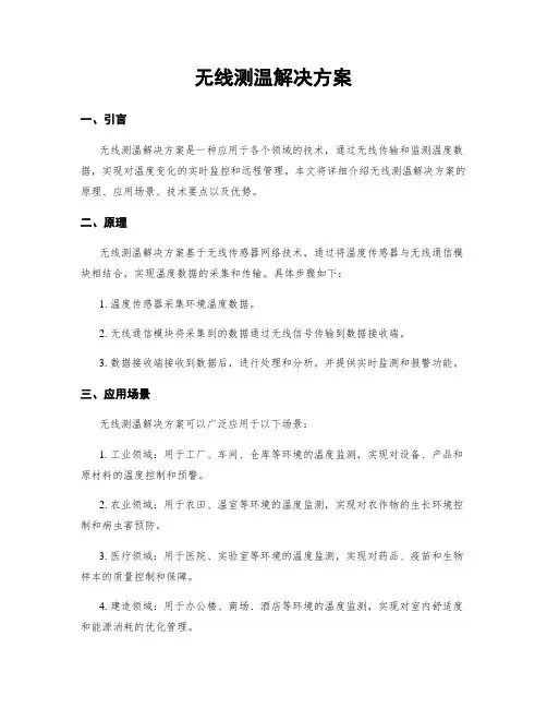
无线测温解决方案一、引言无线测温解决方案是一种应用于各个领域的技术,通过无线传输和监测温度数据,实现对温度变化的实时监控和远程管理。
本文将详细介绍无线测温解决方案的原理、应用场景、技术要点以及优势。
二、原理无线测温解决方案基于无线传感器网络技术,通过将温度传感器与无线通信模块相结合,实现温度数据的采集和传输。
具体步骤如下:1. 温度传感器采集环境温度数据。
2. 无线通信模块将采集到的数据通过无线信号传输到数据接收端。
3. 数据接收端接收到数据后,进行处理和分析,并提供实时监测和报警功能。
三、应用场景无线测温解决方案可以广泛应用于以下场景:1. 工业领域:用于工厂、车间、仓库等环境的温度监测,实现对设备、产品和原材料的温度控制和预警。
2. 农业领域:用于农田、温室等环境的温度监测,实现对农作物的生长环境控制和病虫害预防。
3. 医疗领域:用于医院、实验室等环境的温度监测,实现对药品、疫苗和生物样本的质量控制和保障。
4. 建造领域:用于办公楼、商场、酒店等环境的温度监测,实现对室内舒适度和能源消耗的优化管理。
四、技术要点无线测温解决方案的关键技术要点包括:1. 无线传感器网络技术:通过无线传感器节点的部署和组网,实现对温度数据的采集和传输。
2. 低功耗设计:无线传感器节点采用低功耗芯片和优化算法,延长电池寿命,降低维护成本。
3. 数据安全性:采用加密算法和身份认证机制,保障温度数据的安全传输和存储。
4. 远程管理:通过云平台或者手机应用,实现对温度数据的远程监控、报警和管理。
五、优势无线测温解决方案相比传统有线测温方式具有以下优势:1. 灵便性:无线传感器节点可以灵便部署,适应不同环境和场景的需求。
2. 实时性:无线传输和监测温度数据,实现对温度变化的实时监控和报警。
3. 可扩展性:可以根据需求增加或者减少传感器节点,实现对更大范围的温度监测。
4. 降低成本:无线传感器节点的部署和维护成本相对较低,且不需要布线,减少了工程和材料成本。
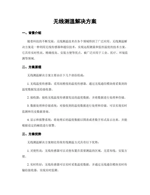
无线测温解决方案一、背景介绍随着科技的不断发展,无线测温技术在各个领域得到了广泛应用。
无线测温解决方案是一种利用无线传感器和通信技术,实现远程测量和监控温度的技术方案。
它具有实时性高、精确度高、安装方便等优点,被广泛应用于工业、医疗、环境监测等领域。
二、方案原理无线测温解决方案主要由以下几个部份组成:1. 无线温度传感器:采用高精度的温度传感器,通过无线通信模块将采集到的温度数据发送给接收器。
2. 接收器:接收无线温度传感器发送的温度数据,并将数据进行处理和存储。
3. 数据处理和存储系统:对接收到的温度数据进行处理和存储,可以实现实时监测和历史数据查询。
4. 显示和报警系统:将处理后的温度数据以图表或者数字形式显示出来,并能根据设定的阈值进行报警。
三、方案优势无线测温解决方案相比传统有线测温方式具有以下优势:1. 灵便性高:无线传感器可以灵便布置在需要测温的区域,无需布线,安装方便。
2. 实时性好:无线传感器可以实时采集温度数据,并通过无线通信模块实时传输给接收器,实现实时监测。
3. 精确度高:采用高精度的温度传感器,保证测温数据的准确性。
4. 扩展性强:无线测温解决方案可以根据实际需求进行扩展,可以同时监测多个测温点。
5. 数据存储和分析:无线测温解决方案可以将采集到的温度数据进行存储和分析,方便用户进行历史数据查询和分析。
四、应用场景无线测温解决方案可以广泛应用于以下场景:1. 工业领域:用于监测工业设备的温度,及时发现异常情况,预防设备故障和事故的发生。
2. 医疗领域:用于监测患者体温,实时掌握患者的健康状况,提供精准的医疗服务。
3. 环境监测:用于监测室内外环境的温度变化,为调控室内温度提供科学依据,提高能源利用效率。
4. 农业领域:用于监测农作物生长环境的温度,匡助农民科学管理,提高农作物产量和质量。
五、实施步骤无线测温解决方案的实施步骤如下:1. 需求分析:根据实际需求确定需要监测的温度点和监测范围。
【上海数采物联网科技有限公司】无线电流采集终端产品说明书版本:V1.1修订记录目录1产品概述 (3)2服务理念 (4)3产品特性 (4)3.1电流采集特性 (4)3.2温度采集特性(可选项) (4)3.3电气特性 (4)3.4互感器通信特性 (5)3.5网关通信特性 (5)3.6结构特性 (5)3.7电磁兼容 (5)3.8工作环境 (6)4产品核心优势 (6)5数据上报通信协议 (6)5.1协议解析说明 (6)5.2协议定制 (7)6平台对接 (7)6.1默认平台 (7)6.2用户指定平台 (8)7应用案例 (9)8安装与维护 (9)8.1电池更换 (9)8.2指示灯 (9)9设备尺寸 (9)1产品概述SC-LP-CTLoRa 无线电流温度采集传感器终端配备低功耗高灵敏度的开口式互感器,通过电磁感应原理将一次侧大电流转换侧二次侧小电流,进而用于电流监测,能够很敏感的探测线路电流的大小,监测回路电流大于产品启动电流,传感器进入正常工作模式,采集温度、电流及其他相关数据,通过无线通讯上传至采集装置。
若线路处于空载或负载电流小于启动电流,则传感器使用内部电池供电保持工作状态。
传感器终端支持采用GPRS/4G/NB-IOT/LoRa/WiFi 通信方式(外接电源默认采用GPRS 通信方式,电池供电默认采用NB-IOT/LoRa 通信方式),克服现场特殊环境导致的无线通信遮挡,大大简化现场部署时间和降低施工费用。
测量电流范围宽,采用优质磁芯材料,开合式结构,易于安装,用于交流电机,照明设备,空气压缩机,采暖通风与空调装置,建筑物的自控制系统,工业中城网,农网改造项目等场景的电流监测采集。
型号特点说明SC-LP-CTLoRA SC-LP-CTNB NB-IOT /loRa 通信,长寿命锂电池供电,适合采集频率低,外接电源困难的场合。
SC-GP-CT01GPRS 通信,220V 交流/12V 直流供电,适合采集频率高或外接电源方便的场合。
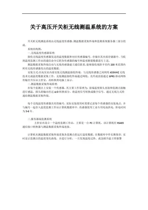
关于高压开关柜无线测温系统的方案开关柜无线测温系统由无线温度传感器、测温数据采集终端和监测系统服务器三部分组成。
系统结构图:一.无线温度传感器原理:接收无线温度传感器发送的温度数据和对应传感器编号,存储在其内部存储器中。
当收到温度监测工作站的通信命令后把各传感器的编号和温度测量数据进行上送。
测温数据采集终端自动与无线传感器建立通信联系,能够接收视距半径约200米范围内所有无线传感器发出的温度数据。
安装方式:在高压室内部安装无线测温接收终端,与无线传感器之间利用433MHZ无线技术完成温度数据采集工作,无线测温接收终端通过网线、光纤或直接通过GPRS移动网络传输至升压站主控室,再转换到电脑上显示。
二.测温数据采集终端原理:在每个监测点上安装一个传感器。
其主要工作原理为:前端温度探头直接和监测点接触进行感温,探头的输出经过A/D转换部分,将温度信号转换成数字信号,通过无线方式传递给测温数据采集终端。
每个无线温度传感器具有的编号,实际安装使用时需要记录每个传感器的安装地点,并与编号一起存入温度监测工作站计算机数据库中。
传感器使用工业专用电池供电,供电时间为5-6年。
三.服务器端监测系统主控室内设立一个温度监测工作站,主要是一台PC计算机,该计算机经RS485通信接口转换器与测温数据采集终端连接。
计算机从测温数据采集终端采集各监测点的运行温度数据,在数据库中作长期保存,实时显示监测点的温度变化曲线,并进行分析,一旦发现温度过热、或急剧升温立即报警软件主要功能:1、定时读取从采集终端中收集的温度和ID数据,并写入本地硬盘中作长期保存。
对数据进行处理、维护,异常报警,以及温度变化趋势分析。
2、实时、直观的观察到发热点运行温度的变化情况。
3、对现场检测到的数据,自动生成触头等发热点指定时间段的温度变化趋势、历史事件统计,以及所需要的曲线图和图表。
4、对所检测到的数据进行分析,提前预知和判断以后多少天内发热点故障并形成报表,并详细显示故障点的位置并打印报表。
常见的25种传感器类型介绍“蓝⾊字”传感器的作⽤实际上是⼀种功能块,其作⽤是将来⾃外界的各种信号转换成电信号。
例如,⽇常⽣活中使⽤的话筒,⼿机中的麦克风,它将声⾳转换成电信号,然后放⼤到最佳范围。
然后,在扬声器的o / p处将电信号变成⾳频信号。
如今传感器所检测的信号近来显著地增加,因⽽其品种也极其繁多。
今天我们来看看传感器的种类吧:1.电阻式传感器电阻式传感器是将被测量,如位移、形变、⼒、加速度、湿度、温度等这些物理量转换式成电阻值这样的⼀种器件。
主要有电阻应变式、压阻式、热电阻、热敏、⽓敏、湿敏等电阻式传感器件。
2.变频功率传感器变频功率传感器通过对输⼊的电压、电流信号进⾏交流采样,再将采样值通过电缆、光纤等传输系统与数字量输⼊⼆次仪表相连,数字量输⼊⼆次仪表对电压、电流的采样值进⾏运算,可以获取电压有效值、电流有效值、基波电压、基波电流、谐波电压、谐波电流、有功功率、基波功率、谐波功率等参数。
3.称重传感器称重传感器是⼀种能够将重⼒转变为电信号的⼒→电转换装置,是电⼦衡器的⼀个关键部件。
能够实现⼒→电转换的传感器有多种,常见的有电阻应变式、电磁⼒式和电容式等。
电磁⼒式主要⽤于电⼦天平,电容式⽤于部分电⼦吊秤,⽽绝⼤多数衡器产品所⽤的还是电阻应变式称重传感器。
电阻应变式称重传感器结构较简单,准确度⾼,适⽤⾯⼴,且能够在相对⽐较差的环境下使⽤。
因此电阻应变式称重传感器在衡器中得到了⼴泛地运⽤。
4.电阻应变式传感器传感器中的电阻应变⽚具有⾦属的应变效应,即在外⼒作⽤下产⽣机械形变,从⽽使电阻值随之发⽣相应的变化。
电阻应变⽚主要有⾦属和半导体两类,⾦属应变⽚有⾦属丝式、箔式、薄膜式之分。
半导体应变⽚具有灵敏度⾼(通常是丝式、箔式的⼏⼗倍)、横向效应⼩等优点。
5.压阻式压阻式传感器是根据半导体材料的压阻效应在半导体材料的基⽚上经扩散电阻⽽制成的器件。
其基⽚可直接作为测量传感元件,扩散电阻在基⽚内接成电桥形式。
UWRH-2-NEMA Especificações(Especificações completas disponíveis na internet) Intervalo de T emperatura:-17 a 49°C (2 a 120°F)Exatidão: ±1°C (±1,8°F)Intervalo de Umidade Relativa: 2 a 98% da URExatidão: ±2,5% da UR de 20 a 80% daO transmissor de umidade relativasem fio da OMEGA possui designautônomo, compacto, alimentadopor bateria e com invólucro NEMAque transmite as medições para umreceptor host a uma distância deaté 120 m (400'). Quando ativado,o transmissor sem fio transmitiráas leituras continuamente em umintervalo de tempo pré-determinadoprogramado pelo usuário durante aconfiguração inicial. Cada unidademede e transmite para o receptor:umidade relativa, temperaturaambiente, intensidade do sinal de RFe nível de carga da bateria. Essasinformações são exibidas na telado seu computador em tempo realusando o software fornecido.Transmissores de Umidade Relativa/Temperatura Sem FioNota:ambos incluídos junto com os receptores e transmissores sem fio da série UW compatíveis.São fornecidos completos com bateria de lítio de 3,6 V, suporte de montagem e manual do usuário.Exemplos de Pedido: UWRH-2-NEma, transmissor de umidade relativa/temperatura sem fio,UWTC-REC1, receptor de 48 canais e UWTC-BaTT-C, bateria de reposição.UWRH-2, transmissor de temperatura/UR sem fio,UWTC-REC1, receptor de 48 canais eUWTC-BaTT, bateria de reposição.e M edem tanto a UmidadeRelativa quanto aTemperaturae T ransmitem a uma Distânciade até 120 m (400')e D isponíveis com InvólucroResistente a IntempériesClassificação NEMA 4X(IP65)e S oftware Gratuito Converteseu Computador emum Gravador Gráfico ouRegistrador de DadosMulticanale T ransmite Umidade Relativa,Temperatura Ambiente,Intensidade do Sinal e Nívelde Carga da Bateriae F unciona com Todos osReceptores e T ransceptoresSem Fio da Série UWTCUWRH-2R e c e p t o re sA d i c i o n a isD i s p o nív ei sTransmissor UWRH-2 mostradoem tamanho inferior ao real.de 80% da UR a 25°C (76°F)Ambiente Operacional:-10 a 70°C (14 a 158°F)Duração da Bateria (Normalmente):UWRH-2: 1 anoU WRH-2-NEMA: 3 anos a uma taxar o v a d o s pe l aF C C/I n d u st r yC a n a d a ep e l aA N A T E LANOGARANTIAW-9。
无线通讯方式的温湿度传感器在烟草行业温湿度测量中的应用说明:该方案也适用于其他需要对环境温、湿度监控的领域,如:成品库、醇化库、发酵库、储丝房等,现仅以某烟叶发酵库为例。
1 概述无线通讯方式的温湿度传器(WOW)是美国PointSix公司新一代高精度数字式传感器,与在线式温湿度传感器相比较,有如下优点:1)1)无线温、湿度传感器的安装位置没有任何限制且无须布线。
(在无线电通讯距离范围内)2)2)无线温、湿度传感器采用防水设计可以应用于非常潮湿的环境。
3)3)无线温、湿度传感器的安装和维护非常简便。
4)4)减少了电缆使用量,降低了系统成本、提高了系统的可靠性。
5)5)如果发酵库翻新,无线温、湿度传感器不存在连接电缆问题可以随意拆卸,不存在重复投资问题。
6)6)系统可以很方便的与空调机的自动控制系统连接。
为便于介绍,下面以某烟厂为例进行方案论述。
该卷烟厂发酵库采用人工发酵,由31间发酵室组成。
每间发酵室可装烟包400~600包,每一发酵周期为15天,每月要完成1万~3万包的发酵任务,保证该卷烟厂年生产计划。
2 人工发酵的基本程序1)1)升温阶段: 温度由室温升至45℃,相对湿度55%-60%,时间3天。
2)2)保温阶段:温度稳定在45℃,相对湿度60%-65%,时间9天。
3)3)降温阶段: 温度逐渐降至室温,时间3天。
3 用户需求分析发酵库现有37名工作人员,采用四班三运转方式,每两个小时派人进发酵室内抄写室内环境温度、湿度、烟包包心温度,全年365天从不间断。
由于发酵室内温湿度通常保持在45℃和60%左右,房间内充满了湿热蒸汽和烟包散发出的刺鼻的烟味,工作环境恶劣,影响操作工身体健康。
而且,采用人工定时记录数据的方式,数据精度、数据的完整性无法保证;数据处理、生产管理仍停留在落后的手工制表的模式下,卷烟厂其他车间相比,发酵库的生产状态监测、生产管理水平确实落后了。
发酵库曾采用苹果机和单板机对温、湿度进行计算机自动检测。
一、实验目的1. 熟悉无线温度检测系统的组成和工作原理。
2. 掌握无线传感器网络(WSN)在温度检测中的应用。
3. 学习使用ZigBee无线通信技术进行数据传输。
4. 培养实验操作能力和数据处理能力。
二、实验原理无线温度检测系统主要由温度传感器、无线传感器网络(WSN)和数据处理单元组成。
温度传感器用于采集环境温度数据,无线传感器网络负责将采集到的温度数据传输到数据处理单元,数据处理单元对温度数据进行处理和分析。
本实验采用ZigBee无线通信技术,其具有低功耗、低成本、高可靠性和低成本等特点,非常适合用于无线温度检测系统。
三、实验器材1. 温度传感器(如DS18B20)2. ZigBee模块(如CC2530)3. 微控制器(如STM32)4. 电源5. 连接线6. 实验平台(如面包板、电路板等)四、实验步骤1. 搭建实验平台(1)将温度传感器连接到微控制器上。
(2)将ZigBee模块连接到微控制器上。
(3)将微控制器连接到实验平台上。
2. 编程(1)编写温度传感器数据采集程序,将采集到的温度数据存储到微控制器的内存中。
(2)编写ZigBee模块数据传输程序,将采集到的温度数据通过无线通信发送到接收端。
(3)编写接收端程序,接收温度数据并显示在屏幕上。
3. 调试(1)检查电路连接是否正确。
(2)检查程序代码是否正确。
(3)进行实际测试,观察温度数据采集和传输是否正常。
4. 数据分析(1)记录实验过程中采集到的温度数据。
(2)分析温度数据的波动情况。
(3)评估无线温度检测系统的性能。
五、实验结果与分析1. 温度数据采集实验过程中,温度传感器成功采集到环境温度数据,并将数据存储到微控制器的内存中。
2. 无线数据传输ZigBee模块成功将温度数据通过无线通信发送到接收端,接收端程序成功接收并显示温度数据。
3. 数据分析实验过程中,温度数据波动幅度较小,说明无线温度检测系统具有良好的稳定性。
同时,实验结果表明,ZigBee无线通信技术在温度检测系统中具有较好的应用前景。
无线测温解决方案引言概述:随着科技的不断发展,无线测温解决方案在工业领域中越来越受到关注。
无线测温技术通过无线传感器实时监测温度,不仅提高了工作效率,还降低了人工操作的风险。
本文将介绍无线测温解决方案的原理、应用领域、优势、挑战以及未来发展方向。
一、无线测温解决方案的原理1.1 无线传感器技术无线测温解决方案依赖于无线传感器技术。
无线传感器通过感知环境中的温度变化,并将数据传输给接收器。
这些传感器可以通过无线通信技术(如Wi-Fi、蓝牙、Zigbee等)与接收器进行通信,实现实时数据传输和监测。
1.2 温度测量原理无线测温解决方案中常用的温度测量原理包括热电偶、热敏电阻和红外测温。
热电偶利用两种不同金属的热电效应来测量温度,热敏电阻则通过电阻随温度变化来测量温度,而红外测温则利用物体辐射的红外能量来测量温度。
1.3 数据处理和分析无线测温解决方案中的数据处理和分析是关键环节。
传感器采集到的温度数据经过无线传输到接收器后,需要进行数据处理和分析。
这些数据可以被用于监测温度变化趋势、预测温度异常等,并通过数据分析算法匡助用户做出决策。
二、无线测温解决方案的应用领域2.1 工业创造无线测温解决方案在工业创造中有广泛的应用。
通过无线传感器实时监测设备的温度,可以及时发现异常情况,避免设备过热或者过冷导致的故障,提高生产效率和设备的寿命。
2.2 医疗保健在医疗保健领域,无线测温解决方案可以用于监测患者的体温。
传感器可以实时测量患者的体温,并将数据传输给监护仪或者医生的挪移设备,及时发现患者体温异常,提供及时的护理和治疗。
2.3 环境监测无线测温解决方案还可以应用于环境监测领域。
通过无线传感器监测环境温度的变化,可以实时掌握环境的温度状况,为气象预报、农业生产等提供重要数据支持。
三、无线测温解决方案的优势3.1 实时监测无线测温解决方案可以实时监测温度变化,及时发现异常情况,避免事故发生。
与传统的手动测温相比,无线测温解决方案大大提高了监测效率。
长 春 大 学 毕业设计(论文)手册
学 院: 电子信息工程学院 专 业: 物联网工程 班 级: 物联网12410 学生姓名: * * 学 号: 021241007
指导教师: 关秀丽(讲师)
长春大学教务处制 二〇一五年十二月 目 录 长春大学毕业设计任务书 ....................................................................................................... 1
长春大学毕业设计开题报告 ................................................................................................. 3
长春大学毕业设计中期检查表 .......................................................................................... 10
长春大学毕业设计指导教师评定表 ............................................................................... 11
长春大学毕业设计审阅人评定表 ..................................................................................... 12
长春大学毕业设计院级答辩考核表 ............................................................................... 13
长春大学毕业设计总评成绩表 .......................................................................................... 14
长春大学毕业设计学生工作记录 ..................................................................................... 15 使 用 说 明 本手册共分为五部分,第一部分是毕业设计(论文)任务书,由指导教师填写,学生针对指导教师任务书的具体内容进行第二部分的撰写。第二部分是开题报告,需学生填写,其成绩由答辩小组经开题答辩后给出。第三部分是中期检查,指导教师根据毕业设计(论文)的计划完成情况给出评语,并给出成绩。第四部分是成绩考核,指导教师、评阅人、答辩委员会(小组)要按照评分标准给出评语并给出评定分数,并根据权重给出总分数,并按五级分制填写总成绩。第六部分为工作记录,需要学生填写,指导教师填写评语。 本手册作为毕业设计(论文)工作的重要文件资料,由学生妥善保管,答辩时学生须向答辩委员会(小组)提交本手册,没有本手册或本手册填写不完备不能参加答辩。整个毕业设计(论文)过程,指导教师要随时对学生进行检查,同时在手册的相应部位签字。 本手册最后装入学生毕业设计(论文)资料袋。 - 1 -
长春大学毕业设计任务书 毕业设计 题 目 基于无线传感器网络的温度控制系统设计
起 止 日 期 2015-2016-1(13-14周) 2015-2016-2( 9-16周) 共计10周
学生姓名 王贺 学号 021241007 专业 物联网工程 指导教师 关秀丽 所在系室 测量与控制工程 职称 讲师 毕业设计基本内容 本系统是基于nRF24L01 的远程温度测量与监控,广泛用于电力工业、粮食存储、火灾等场合。系统通过单片机向数字式温度传感器发送命令,读取转换的温度数据,实现对温度的控制。当测量的温度超过设定的报警温度时,发出报警信号,然后单片机把温度数据送到发射端nR F24L01的发射缓存器,通过无线方式把温度数据发射出去。接收端nRF24L01接收发送过来的温度数据,并有单片机读取保存,然后通过串口与PC通信。本系统的外围电路可以包括单片机的最小系统、显示电路、按键处理电路及发射和接收电路等。
主要技术指标 本系统具有以下功能: 1、监控的温度范围-55C0~+125C0,精度0.5C0 2、利用无线射频手法芯片实现对温度的发送与接收 3、实时显示系统的温度 4、温度超过上限报警 - 2 -
设计(论文)要求
设计结果 □电路图纸 □仿真模拟 ■其他 论文字数 1.5万字 译文字数 3000字 实物制作 □是 ■ 否
毕业设计所需的参考资料(教师指定)
[1]北京教育科学研究院.无线电技术基础[M].北京:人民邮电出版社,2005. [2]李文忠,段朝玉.短距离无线数据通信[M].北京:北京航空航天大学出版社,2006. [3]Guiyun Tian.Foundation and Application of Microcontroller[M].北京:高等教育出版社, 2004. [4] IEEE Std 802.15.4-2006.Wireless medium access control(MAC) and physical layer(PHY) pecifications for low-rate wireless ersonal area networks(WPANs)[D].万方数据服务平台,2010. [5] 李江权;基于无线传感器网络的环境监测系统研究[D];南京大学;2012年 [6] 冯俊,物联网信息采集系统的设计与实现[J];电脑知识与技术;2011年28期 [7] 孙霞;多路高精度温度监测系统[D];山东科技大学;2004. [8]朱玉颖,蔡占辉.基于nRF24L01的远程温度检测系统设计[J] .通信与信息处理,2010. [9]马祖长,孙怡宁.无线传感器网络综述[J].通信学报.2004. [10] Elson J,Estrin D,Wireless Sensor Netwoks:A Bridge to the Physical World[M].Wireless Sensor Networks.2004. [11] L.Clare,G.Pottie,J.Agre. Self-organizing distributed sensor networks[J], SPIE-The International Society for Optical Engineering,1999. [12] Callaway E H. Wireless Sensor Network: Architecture and Protocols[J].CRC Press LIC,2004. [13]Proceedings of 2010 International Conference on Services Science, Management and Engineering(Volume 2)[C];2010. [14] Xiao-Ming Deng,Yan Xiong .New Protocol for the Detection of Node Replication Attacks in Mobile Wireless Sensor Networks[D]. Journal of Computer Science and Technology,2011. [15] Cai Wenyu , Zhang Meiyan . MST-BASED CLUSTERING TOPOLOGY CONTROL ALGORITHM FOR WIRELESS SENSOR NETWORKS[D]. JOURNAL OF ELECTRONICS(CHINA).2010. - 3 -
长春大学毕业设计开题报告 毕业设计 题 目 基于无线传感器网络的温度控制系统设计
学生姓名 王贺 学号 021241007 专业 物联网工程 指导教师 关秀丽 所在系室 测量与控制工程 职称 讲师 1.课题研究的目的和意义 随着社会的进步和生产的需要,利用无线通信进行温度数据采集的方式应用已经渗透到生活各个方面。 在工业现场,由于生产环境恶劣,工作人员不能长时间停留在现场观察设备是否运行正常,就需要采集数据并传输数据到一个环境相对好的操控室内,这样就会产生数据传输问题。由于厂房大、需要传输数据多,使用传统的有线数据传输方式就需要铺设很多很长的通讯线,浪费资源,占用空间,可操作性差,出现错误换线困难。而且,当数据采集点处于运动状态、所处的环境不允许或无法铺设电缆时,数据甚至无法传输,此时便需要利用无线传输的方式进行数据采集。 在农业生产上,不论是温室大棚的温度监测,还是粮仓的管理,传统上都是采取分区取样的人工方法,工作量大,可靠性差。而且大棚和粮仓占地面积大,检测目标分散,测点较多,传统的方法已经不能满足当前农业发展的需要。当前的科技水平下,无线通信技术的发展使得温度采集测量精确,简便易行。 在日常生活中,随着人们生活水平的提高,居住条件也逐渐变得智能化。如今很多家庭都会安装室内温度采集控制系统,其原理就是利用无线通信技术采集室内温度数据,并根据室内温度情况进行遥控通风等操作,自动调节室内温度湿度,可以更好地改善人们的居住环境。 以上只是简单列举几个现实的例子,在现实生活中,这种无线温度采集系统已经被成功应用于工农业、环境监测、军事国防、机器人控制等许多重要领域,而且类似于这种温度采集系统的无线通信网络已经被广泛的应用到民用和军事领域。凡是布线繁杂或不允许布线的场合都希望能通过无线方案来解决。为此,需要设计相应的接口系统,控制这些射频芯片工作,完成可靠稳定的无线数据通信,这样的研究也变得更加有意义了。