
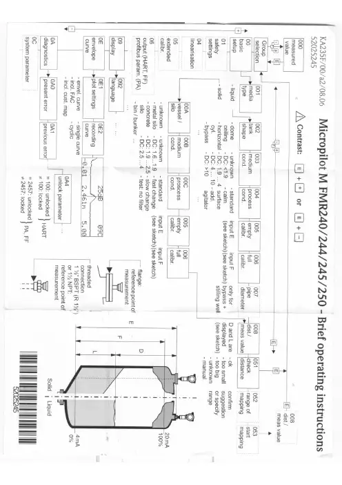
FMR240-244-245-250操作手册
- 格式:pdf
- 大小:657.12 KB
- 文档页数:1


Products Solutions Services简明操作指南Micropilot FMR20HART雷达物位仪本文档为《简明操作指南》;不得替代设备的《操作手册》。
设备的详细信息请参考《操作手册》和其他文档资料:所有设备型号均可通过以下方式查询:•网址:/deviceviewer•智能手机/平板电脑:Endress+Hauser Operations AppKA01248F/00/ZH/01.1671331405Micropilot FMR20 HART2Endress+HauserMicropilot FMR20 HART 目录Endress+Hauser 3目录1文档信息 (4)1.1特定信息图标.........................................................................41.2安全图标............................................................................41.3图中的图标 (4)2术语和缩写 (53)注册商标 (5)4基本安全指南 (6)4.1人员要求............................................................................64.2指定用途............................................................................64.3工作场所安全.........................................................................64.4操作安全............................................................................74.5产品安全............................................................................75产品描述 (8)5.1产品设计 (8)6到货验收和产品标识 (9)6.1到货验收............................................................................96.2产品标识 (10)7安装.............................................................................127.1安装条件 (12)8电气连接 (22)8.1电缆分配...........................................................................228.2供电电压...........................................................................228.3连接...............................................................................238.4连接后检查 (26)9可操作性 (27)9.1操作方法...........................................................................279.2采用Bluetooth®无线技术...............................................................279.3通过HART 通信 (28)10调试和操作 (28)10.1安装检查和功能检查..................................................................2810.2通过SmartBlue (app)进行操作和设置.....................................................2810.3通过HART 通信实现系统集成...........................................................3510.4通过RIA15进行操作和设置.............................................................3610.5通过调试工具进行液位测量设置..........................................................3910.6数据访问 - 安全性....................................................................4211补充文档资料 (44)11.1标准文档资料........................................................................4411.2补充文档资料........................................................................4411.3《安全指南》(XA).. (44)文档信息Micropilot FMR20 HART 1 文档信息1.1 特定信息图标1.2 安全图标1.3 图中的图标4Endress+HauserMicropilot FMR20 HART 术语和缩写Endress+Hauser 52术语和缩写3 注册商标组织(奥斯汀,美国)的注册商标Bluetooth®名称和LOGO 是Bluetooth SIG 公司的注册商标,Endress+Hauser 拥有使用权。

SD00327F/00/EN/13.1071125885Functional Safety ManualMicropilot MFMR230/231, FMR240/244/245, FMR250Level-Radarwith 4 to 20 mA Output SignalApplicationOperating minimum (e.g. dry run protection) andmaximum (e.g. overfill protection) detection of powdery to granular bulk solids and all types of liquids in systems to satisfy particular safety systems requirements as per IEC 61508/IEC 61511.The measuring device fulfils the requirements concerning•Functional safety as per IEC 61508/IEC 61511•Explosion protection (depending on the version)•Electromagnetic compatibility as per EN 61326 and NAMUR recommendation NE 21•Electrical safety as per IEC/EN 61010-1Your benefits•Used for level monitoring (MIN, MAX) up to SIL 2–Independently assessed (Functional Assessment) by as per IEC 61508/IEC 61511•Permanent self-monitoring •Continuous measurement•Non-contact measurement: measurement is virtually independent of product properties •Easy commissioningMicropilot M Table of contentsSIL Declaration of Conformity. . . . . . . . . . . . . . . . . . .3Introduction. . . . . . . . . . . . . . . . . . . . . . . . . . . . . . . . .4Structure of the measuring system. . . . . . . . . . . . . . . .4System components . . . . . . . . . . . . . . . . . . . . . . . . . . . . . . . . . . . 4Description of use as a protective system . . . . . . . . . . . . . . . . . . . . 5Permitted device types . . . . . . . . . . . . . . . . . . . . . . . . . . . . . . . . . 5Supplementary device documentation . . . . . . . . . . . . . . . . . . . . . . 7Description of the safety requirements andboundary conditions . . . . . . . . . . . . . . . . . . . . . . . . . .8Safety function . . . . . . . . . . . . . . . . . . . . . . . . . . . . . . . . . . . . . . . 8Restrictions for use in safety-related applications . . . . . . . . . . . . . . 8Functional safety indicators . . . . . . . . . . . . . . . . . . . . . . . . . . . . . . 9Behavior of device during operation and in case of error . . . . . . . 11Installation . . . . . . . . . . . . . . . . . . . . . . . . . . . . . . . . . . . . . . . . . 11Operation . . . . . . . . . . . . . . . . . . . . . . . . . . . . . . . . . . . . . . . . . . 11Maintenance . . . . . . . . . . . . . . . . . . . . . . . . . . . . . . . . . . . . . . . 14Proof-test. . . . . . . . . . . . . . . . . . . . . . . . . . . . . . . . . .15Proof-test . . . . . . . . . . . . . . . . . . . . . . . . . . . . . . . . . . . . . . . . . . 15Process for proof-testing . . . . . . . . . . . . . . . . . . . . . . . . . . . . . . . 15Repairs. . . . . . . . . . . . . . . . . . . . . . . . . . . . . . . . . . . .16Repairs . . . . . . . . . . . . . . . . . . . . . . . . . . . . . . . . . . . . . . . . . . . . 16Appendix. . . . . . . . . . . . . . . . . . . . . . . . . . . . . . . . . .17Commissioning or proof test protocol . . . . . . . . . . . . . . . . . . . . . 17Exida Management Summary . . . . . . . . . . . . . . . . . .182Endress+HauserMicropilot MEndress+Hauser 3SIL Declaration of ConformitySIL_08006a_deMicropilot M4Endress+HauserIntroduction!Note!General information on functional safety (SIL) is available at:/SIL (German) or /SIL (English) and in Competence Brochure CP002Z "Functional Safety in the Process Industry - Risk Reduction with Safety Instrumented Systems".Structure of the measuring systemSystem componentsThe measuring system's devices are displayed in the following diagram (example).An analog signal (4 to 20 mA) in proportion to the level is generated in the transmitter. This is sent to adownstream logic unit (e.g. PLC, limit signal transmitter, etc.) where it is monitored to determine whether it is below or above a specified limit value.For fault monitoring, the logic unit must recognize both HI-alarms (≥ 21.0 mA) and LO-alarms (≤ 3.6 mA).Micropilot MEndress+Hauser 5Description of use as a protective systemThe Micropilot M is a "downward-looking" measuring system that functions according to the ToF method (ToF = Time of Flight). The distance from the reference point (process connection of the measuring device) to the product surface is measured. Radar impulses are emitted by an antenna, reflected off the product surface and received again by the radar system.Typical measuring arrangement:!Note!Correct installation is a prerequisite for safe operation of the device.Permitted device typesThe details pertaining to functional safety in this manual relate to the device versions listed below and are valid as of the specified software and hardware version. Unless otherwise specified, all subsequent versions can also be used for safety instrumented systems.A modification process according to IEC 61508 is applied for device changes.Valid device versions for safety-related use:Micropilot M FMR230, FMR244FeatureDesignation Version 010Approval all 020Antennaall 030Antenna Seal; Temperature all 040Process Connection all 050Output; Operation A, B, K 060Housing all 070Cable Entry all 080Additional OptionallValid software version: FMR230: as of 01.04.00; FMR244: as of 01.05.00Valid hardware version (electronics): as of delivery date January 2010Micropilot MMicropilot M FMR231Feature Designation Version010Approval all020Antenna; Inactive Length all030Process Connection all040Output; Operation A, B, K050Housing all060Cable Entry all070Gas-Tight Feed Through all080Additional Option allValid software version: FMR231: as of 01.04.00Valid hardware version (electronics): as of delivery date January 2010Micropilot M FMR240, FMR250Feature Designation Version010Approval all020Antenna all030Antenna Seal; Temperature all040Antenna Extension all050Process Connection all060Output; Operation A, B, K070Housing all080Cable Entry all090Additional Option allValid software version: FMR240, FMR250: as of 01.05.00Valid hardware version (electronics): as of delivery date January 2010Micropilot M FMR245Feature Designation Version010Approval all020Antenna all030Process Connection all040Output; Operation A, B, K050Housing all060Cable Entry all070Additional Option allValid software version: FMR245: as of 01.05.00Valid hardware version (electronics): as of delivery date January 20106Endress+HauserMicropilot MEndress+Hauser 7Supplementary device documentationDocumentationContentsCommentTechnical InformationTI00345F/00 (FMR23x, FMR24x)TI00390F/00 (FMR250)–Technical data–Instructions on accessories –The documentation is available on the Internet.→ .Operating Instructions (HART)BA00218F/00 (FMR230)BA00219F/00 (FMR231)BA00220F/00 (FMR240)BA00248F/00 (FMR244)BA00251F/00 (FMR245)BA00284F/00 (FMR250)–Identification –Installation –Wiring –Operation–Commissioning –Maintenance –Accessories –Troubleshooting –Technical data –Appendix–The documentation is supplied with the device.–The documentation is also available on the Internet.→ .Operating Instructions (Device Functions)BA00221F/00 (FMR23x)BA00291F/00 (FMR24x, FMR250)–Instructions on use–Micropilot M function menu –Function groups ...–...–Envelope curve –Troubleshooting–Function menu index–The documentation is available on the Internet.→ .Safety instructions depending on the selected version "Approval"–Safety, installation and operating instructions for devices, which are suitable for use in potentially explosive atmospheres or as overfill protection (WHG, German Water Resources Act).Additional safety instructions(XA, XB, XC, ZE, ZD) are supplied with certified device versions.Please refer to the nameplate for the relevant safety instructions.Micropilot M8Endress+HauserDescription of the safety requirements and boundary conditionsSafety functionThe mandatory settings and safety function data emanate from the descriptions from →ä11.The measuring system's reaction time is ≤ 5 s.!Note!MTTR is set at 8 hours.Safety-related signal:The Micropilot M's safety-related signal is the 4 to 20 mA analog output signal. All safety measures refer to this signal exclusively.The Micropilot M additionally communicates effectively via HART and contains all HART features with additional device information.The safety-related output signal is fed to a downstream logic unit, e.g. a programmable logic controller or a limit signal transmitter where it is monitored for the following:–Overshooting and/or undershooting a specified level limit.–The occurrence of a fault, e.g. error current (≤ 3.6 mA, ≥ 21.0 mA, interruption or short-circuit of the signal line).Restrictions for use in safety-related applicationsThe measuring system must be used correctly for the specific application, taking into account the medium properties and ambient conditions. Carefully follow instructions pertaining to critical process situations and installation conditions from the Operating Instructions.The specifications from the Operating Instructions (→ä7, "Supplementary device documentation") must not be exceeded.The following restriction also applies to safety-related use:–The accuracy of the 4 to 20 mA safety-related output signal is ± 10%.Micropilot MFunctional safety indicators The following tables show specific indicators for functional safety.Characteristic as per IEC 61508FMR23x with 4 to 20 mA outputSafety functions MIN MAXSIL2HFT0Device type BMode of operation Low demand modeSFF 67 % 74 %MTTR8 hRecommended time interval for proof-testing T1 1 yearλsd *2 392 FIT 87 FITλsu *2951 FIT1125 FITλdd *2541 FIT846 FITλdu *2916 FIT710 FITλtot *32800 FIT2768 FITPFD avg for T1 = 1 year *14,01 × 10-33,11 × 10-3PFD avg for T1 = 1 year *54,75 × 10-33,69 × 10-3MTBF *335 yearsSystem reaction time *4≤ 5 s*1 PFD avg*2 According to Siemens SN29500.*3 According to Siemens SN29500, including faults outside the safety function.*4 Step response time as per DIN EN 61298-2.*5 Calculated, with MTTR = 24 h, lifetime (LT) = 10 years and proof test coverage (PTC) = 98 %,Proof-test intervalEndress+Hauser9Micropilot MCharacteristic as per IEC 61508FMR24x, FMR250 with 4...20 mA outputSafety functions MIN MAXSIL2HFT0Device type BMode of operation Low demand modeSFF 68 % 75 %MTTR8 hRecommended time interval for proof-testing T1 1 yearλsd *2 356 FIT 99 FITλsu *21031 FIT1207 FITλdd *2621 FIT878 FITλdu *2903 FIT697 FITλtot *32911 FIT2881 FITPFD avg for T1 = 1 year *13,96 × 10-33,05 × 10-3PFD avg for T1 = 1 year *54,68 × 10-33,62 × 10-3MTBF *335 yearsSystem reaction time *4≤ 5 s*1 PFD avg*2 According to Siemens SN29500.*3 According to Siemens SN29500, including faults outside the safety function.*4 Step response time as per DIN EN 61298-2.*5 Calculated, with MTTR = 24 h, lifetime (LT) = 10 years and proof test coverage (PTC) = 98 %,Proof-test interval10Endress+HauserDangerous undetected failures in this scenario:An incorrect output signal that deviates from the real measured value by more than 10%, but is still in the range of 4 to 20 mA, is considered a dangerous, undetected failure.Useful lifetime of electrical components:The established failure rates of electrical components apply within the useful lifetime as per IEC 61508:2000, section 7.4.7.4. note 3.Behavior of device during operation and in case of error Behavior of device during power-upThe safe 4 to 20 mA output signal is available after 17 s after the device is switched on or when the voltage returns.Device response in the event of alarms or warningsError currentIn the event of an alarm, the output current can be configured to a value of ≤ 3.6 mA or ≥ 21.0 mA.In some cases (e.g. failure of power supply, a cable open circuit and faults in the current output itself, where the error current ≥ 21.0 mA cannot be set), output currents ≤ 3.6 mA irrespective of the configured error current can occur.For alarm monitoring, the logic unit must therefore be able to recognize both HI-alarms (≥ 21.0 mA) and LO-alarms (≤ 3.6 mA).Alarm and warning messagesAdditional information is available in the form of fault codes on the alarm and warning messages output.Installation Installation, wiring and commissioningInstallation, wiring and commissioning of the device is described in the accompanying Operating Instructions(→ä7, "Supplementary device documentation").OrientationThe permitted orientations of the device are described in the Operating Instructions.Operation Calibration of the measuring pointCalibration of the measuring point is described in the Operating Instructions.The method of device configuration!Note!Altered settings (display/FieldCare) in the "extended calibr." function group (Pos. 05) such as "offset" or"curr.turn down" (Pos. 063) in the "output" function group have an effect on the output signal.This must be taken into account when calculating the response height (see relevant Operating Instructions).We recommend that you check that the behavior of the current signal matches the expected behavior by meansof level simulation (correctness of configuration).Configuration schemata/basic calibrationThe parameters are safety-oriented with the "WHG" setting in 018 (→ information in the following table).As an alternative to activating the "WHG" setting, it is also possible to make the safety-oriented setting manually. In doing so, please observe the information in the table below.!Note!The parameters in italics are located on the service level, which can be opened with the code "300".FieldCare / Display - plain text displayDisplay VU331 Position Media type (only FMR24x, FMR250 (software version 01.05.00))001↓Tank shape *1 (FMR23x, FMR24x) or Bin type (FMR250)002↓Medium property003↓Process conditions004↓Empty calibration E005↓Full calibration F006↓Pipe diameter (for bypass / stilling well)007↓MappingSee Operating Instructions ↓Further settings: function group 05See Operating Instructions ↓Overfill protection WHG018↓On-site locking: 3 keys on the VU331 displayYes *1 For FMR 240 with wave guide antenna, stilling well must always be selected as tank shape.FieldCare /Display - plain text display Value/parameterDisplay VU331CommentSafety settings Output on ALARM Max. 110 %, 22 mA 010Parameter must be configured in this way Output echo loss ALARM 012Parameter must be configured in this way Delay time1 s014→ Note 1In safety distance SD self holding016→ Note 3!Note! 1.This parameter determines the reaction time of the device in the event of echo loss; a setting of less than 30 s is recommended.2.This parameter determines the reaction time of the device; deviating settings are possible.In case of changes in "process cond." (004) it is automatically adjusted. The corresponding reaction time is indicated in the documentation BA.3.This parameter can be selected differently, depending on the application.A measuring condition (echo) which results in an ALARM in the "Safety distance SD" area can be reset or deleted by–confirming the ALARM in Pos. 017 locally by means of the VU331 LCD display;–confirming the alarm via the communication protocol (HART) (FieldCare: "ackn. alarm" under safety settings).FieldCare /Display - plain text display Value/parameterDisplay VU331CommentFiltering/averaging/delay Envelope statistics up 20D23→ Note 2Envelope statistics down 20D24→ Note 2MAM filter length 50D11→ Note 2MAM filter border 10D12→ Note 2Output damping 0058→ Note 2Echo detection FEF edge (nur bei MIN)00D56Parameter must be configured in this way FAC mode FMC rising 0D99Parameter must be configured in this way FAC adder6 dB 0D35Parameter must be configured in this way Tank bottom detection OFF0D61Parameter must be configured in this way First echo factor unchanged, but if previously smaller than 30, than: 0D530D51→ Note 3FEF threshold 00D52→ Note 3FEF at near distance 30 dB 0D53→ Note 3FEF distance near 500 mm 0D54→ Note 3FEF distance far 3000 mm0D55Parameter must be configured in this way Max. filling speed 0 mm/s (factory setting)0D15Parameter must be configured in this way Max. drain speed 0 mm/s (factory setting)0D16Parameter must be configured in this wayOtherDetection window OFF0A7Parameter must be configured in this way Hysterese width 0 mm (factory setting)0D14Parameter must be configured in this way Communication address 0060Parameter must be configured in this way Current output mode "Standard" if previously "Fixed current" 063Parameter must be configured in this way SimulationSim. / OFF065Parameter must be configured in this wayLockingThe device must be locked once the Micropilot M has been calibrated as per the Operating Instructions.Type of locking Code/action Position/VU331 displayHardware (recommended) 3 keys together "lock"Locally via VU331 display (keys O and S and F)↓Software (mandatory)WHG (german)018UnlockingThe device is unlocked by firstly removing the hardware lock by locally pressing all the three keys together viathe VU331 LCD display and then by setting the "Overfill protection" parameter (Position 018) to "Standard" ifnecessary.Type of unlocking Code/action Position/VU331 displayHardware (if locked) 3 keys together "unlock"Locally via VU331 display (keys O and S and F)↓Software Standard018Maintenance Please refer to the relevant Operating Instructions (→ä7, "Supplementary device documentation") forinstructions on maintenance and recalibration.Alternative monitoring measures must be taken to ensure process safety during configuration, proof-testing andmaintenance work on the device.Proof-testProof-test Check the operativeness and safety of safety functions at appropriate intervals!The operator must determine the time intervals.You can refer to the diagram "Proof-test interval" →ä9, →ä10, for this purpose.Proof-testing of the device can be performed as follows:–Approaching the level (→ test sequence A).–Removing the device and measuring a medium with comparable properties (→ test sequence B).You must also check that all cover seals and cable entries are sealing correctly.Process for proof-testing Test sequence APreparation1.Connect suitable measuring device (recommended accuracy better ±0.1 mA) to the current output.2.Determine the safety setting (level limit monitoring).Procedure for level limit monitoring1.Approach the level directly below (MAX monitoring) or directly above (MIN monitoring) the level limitto be monitored.2.Read the output current, record it and assess for accuracy.3.Approach the level directly above (MAX monitoring) or directly below (MIN monitoring) the level limitto be monitored.4.Read the output current, record it and assess for accuracy.5.The test is deemed successful if the current in step 2 does not result in activation of the safety functionbut the current in step 4 does.!Note!The proof-test is deemed to have failed if the expected current value deviates for a specific level by >±10%.For troubleshooting, → Operating Instructions (→ä7, "Supplementary device documentation"), Section 9.98% of dangerous, undetected failures are detected using this test.Test sequence BPreparation1.Prepare the test tank with the medium (dielectric constant comparable to that of the medium to bemeasured).For installation instructions, → Operating Instructions (→ä7, "Supplementary devicedocumentation"), Section 3.2.Remove the device and mount it in the test tank.3.Perform interference echo mapping if the shape and size of the test tank is different.4.Connect suitable measuring device (recommended accuracy better than ±0.1 mA) to the current output.5.Determine the safety setting (level limit monitoring).Procedure for level limit monitoring→ Test sequence A!Note!The proof-test is deemed to have failed if the expected current value deviates for a specific level by > ±10%.For troubleshooting, → Operating Instructions (→ä7, "Supplementary device documentation"), Section 9.98% of dangerous, undetected failures are detected using this test."Caution!If an interference echo mapping was performed in the test tank, a valid interference echo mapping must beperformed after the device is mounted in the original tank.!Note!If one of the test criteria from the test sequences described above is not fulfilled, the device may no longer beused as part of a safety instrumented system.The purpose of proof-testing is to detect random device failures. The impact of systematic faults on the safetyfunction is not covered by this test and must be assessed separately.Systematic faults can be caused, for example, by process material properties, operating conditions, build-up orcorrosion.RepairsRepairs Repairs on the devices must always be carried out by Endress+Hauser.Safety functions cannot be guaranteed if repairs are carried out by anybody else.Exception:The following components can be replaced by the customer if the person responsible for doing so has beentrained beforehand by Endress+Hauser:–Sensor–HF module–Electronic insert–Terminal moduleThe replaced components must be sent to Endress+Hauser for the purpose of fault analysis.Once the components have been replaced, a proof-test must be carried out as per test sequence A (→ä15)or test sequence B (→ä15).In the event of failure of a SIL-labeled Endress+Hauser device, which has been operated in a protectionfunction, the "Declaration of Contamination and Cleaning" with the corresponding note "Used as SIL device inprotection system" must be enclosed when the defective device is returned.Please refer to the Section "Return" in the Operating Instructions (→ä7, "Supplementary devicedocumentation").AppendixCommissioning or proof test ArrayprotocolExida Management SummaryEndress+Hauser2122Endress+HauserEndress+Hauser23Instruments InternationalEndress+HauserInstruments International AGKaegenstrasse 24153 ReinachSwitzerlandTel.+41 61 715 81 00Fax+41 61 715 25 00***************.comSD00327F/00/EN/13.1071125885FM+SGML 6.071125885。

技术资料I 345FEN/00/en智能雷达料位变送器,非接触式连续物位测量仪表。
成本效益的4…20 mA 2线技术,适用于防爆区。
TMicropilot M FMR230/231/240/244/245的料位。
汽的影响。
•。
此外,它的准确度是±3 mm,导波管为水平圆柱形储罐提供方案。
优•、浮子测量方案,双线技术减使仪表容易与现有系统• 非接触测量:测量与产品的特性几乎无关。
• MR231)的频率。
PROFIBUS/PA、FOUNDATION•线• 度的杆状天线:• 护安全应用,最高可达到IEC 61508/IEC 61511-1 的 SIL 2 功能安全要求。
应用Micropilot M 用于非接触连续测量液体、浆状物质和泥浆测量不受介质改变、温度变化、气膜或蒸• FMR 230特别适合缓冲器和过程储罐的测量。
• FMR 231在要求化学相容性高时有它自身的优点。
FMR 240 的小型喇叭天线(1 ½″)特别适用于小的容器了解决点:价格低廉的双线技术:取代差压少了接线费用并结合。
• 容易通过菜单驱动的文字数字显示器进行现场操作。
• 借助 ToF Tool 操作软件容易试车、文件化和诊断。
两个频率范围 - 约(6FMR230/F和26GHz (FMR240/244/245),每种应用有恰当的,互不相关• HART或Fieldbus协议通信。
高温:适用的过程温度最高 200℃,高温天的最高温度可达 400℃。
有无效长能够可靠地测量有冷凝水和结垢的狭长喷嘴。
系统的溢出保Micropilot M目录. . . . . .功能和系统设计 . . . . . . . . . . . . . . . . . . . . . . . . .3运行条件:过程. . . . . . . . . . . . . . . . . . . . . . . . . .33测量原理 . . . . . . . . . . . . . . . . . . . . . . . . . . . . . . . . . . . . . 3 过程温度范围 . . . . . . . . . . . . . . . . . . . . . . . . . . . . . . . 33 Equipment architecture . . . . . . . . . . . . . . . . . . . . . . . . . . 4 过程温度极限. . . . . . . . . . . . . . . . . . . . . . . . . . . . . . .33介电常数. . . . . . . . . . . . . . . . . . . . . . . . . . . . . . . . . . .33输入. . . . . . . . . . . . . . . . . . . . . . . . . . . . . . . . . . . . . . 9测量变量. . . . . . . . . . . . . . . . . . . . . . . . . . . . . .9机械结构. . . . . . . . . . . . . . . . . . . . . . . . . . . . . . .34测量范围. . . . . . . . . . . . . . . . . . . . . . . . . . . . . . . . 9 设计,尺寸. . . . . . . . . . . . . . . . . . . . . . . . . . . . . . . . . .34测量条件. . . . . . . . . . . . . . . . . . . . . . . . . . . . 13重量. . . . . . . . . . . . . . . . . . . . . . . . . . . . . . . . . . . . . . .04工作频率. . . . . . . . . . . . . . . . . . . . . . . . . . . . . 13材料. . . . . . . . . . . . . . . . . . . . . . . . . . . . . . . . . . . . . . . .40过程连接. . . . . . . . . . . . . . . . . . . . . . . . . . . . . . . . . . ..40输出 . . . . . . . . . . . . . . . . . . . . . . . . . . . . . . . . . . . . . . . . .14密封. . . . . . . . . . . . . . . . . . . . . . . . . . . . . . . . . . . . . . .40输出信号 . . . . . . . . . . . . . . . . . . . . . . . . . . . . . . . . . . . . .14天线. . . . . . . . . . . . . . . . . . . . . . . . . . . . . . . . . . . . . .40报警信号 . . . . . . . . . . . . . . . . . . . . . . . . . . . . . . . . .. . . . 14线性化 . . . . . . . . . . . . . . . . . . . . . . . . . . . . . . . . . .. . . . . 14人机接口 . . . . . . . . . . . . . . . . . . . . . . . . . . . . . . 41操作concept . . . . . . . . . . . . . . . . . . . . . . . . . . . . . . . . . 14辅助电源 . . . . . . . . . . . . . . . . . . . . . . . . . . . . . . . . . . . . . 14显示元件. . . . . . . . . . . . . . . . . . . . . . . . . . . . . . . . . . .41电气连接 . . . . . . . . . . . . . . . . . . . . . . . . . . . . . . . . . . . . .14操作元件. . . . . . . . . . . . . . . . . . . . . . . . . . . . . . . . . . .42端子排列 . . . . . . . . . . . . . . . . . . . . . . . . . . . . . . . . . . . . .15现场操作. . . . . . . . . . . . . . . . . . . . . . . . . . . . . . . . . . .43负载HART . . . . . . . . . . . . . . . . . . . . . . . . . . . . . . . . . . . 16远方操作. . . . . . . . . . . . . . . . . . . . . . . . . . . . . . . . . . . 44电源电压 . . . . . . . . . . . . . . . . . . . . . . . . . . . . . . . . . . . . .16电缆套管 . . . . . . . . . . . . . . . . . . . . . . . . . . . . . . . . . . . . .16认证和批准 . . . . . . . . . . . . . . . . . . . . . . . . . . . .47功率消耗 . . . . . . . . . . . . . . . . . . . . . . . . . . . . . . . . . . . . . 61CE 认可. . . . . . . . . . . . . . . . . . . . . . . . . . . . . . . . . . . .47电流消耗 . . . . . . . . . . . . . . . . . . . . . . . . . . . . . . . . . . . . . 16Ex 认证. . . . . . . . . . . . . . . . . . . . . . . . . . . . . . . . . . . .47 Ripple HART . . . . . . . . . . . . . . . . . . . . . . . . . . . . . . . . . .16卫生相容性. . . . . . . . . . . . . . . . . . . . . . . . . . . . . . . . .47最大噪音HART . . . . . . . . . . . . . . . . . . . . . . . . . . . . . . . 16溢出保护. . . . . . . . . . . . . . . . . . . . . . . . . . . . . . . . . . .74过压保护器 . . . . . . . . . . . . . . . . . . . . . . . . . . . . . . . . . . . 16船级证书. . . . . . . . . . . . . . . . . . . . . . . . . . . . . . . . . . .47外来标准和指令 . . . . . . . . . . . . . . . . . . . . . . . . . . . . .47性能特点 . . . . . . . . . . . . . . . . . . . . . . . . . . . . . . . . . . . .. 17射频认可. . . . . . . . . . . . . . . . . . . . . . . . . . . . . . . . . . .471压力测量设备指令 . . . . . . . . . . . . . . . . . . . . . . . . . . . 47参考运行条件 . . . . . . . . . . . . . . . . . . . . . . . . . . . . . . . . .7最大测量误差 . . . . . . . . . . . . . . . . . . . . . . . . . . . . . . . . . 17分辨率 . . . . . . . . . . . . . . . . . . . . . . . . . . . . . . . . . . . . .. . 17定货信息. . . . . . . . . . . . . . . . . . . . . . . . . . . . . . .48 Reaction time . . . . . . . . . . . . . . . . . . . . . . . . . . . . . . . . . . 17Micropilot M FMR230 . . . . . . . . . . . . . . . . . . . . . . . . . 84环境温度的影响. . . . . . . . . . . . . . . . . . . . . . . . . . . . .. . 17Micropilot M FMR231 . . . . . . . . . . . . . . . . . . . . . . . . . 51Micropilot M FMR240 . . . . . . . . . . . . . . . . . . . . . . . . 54运行条件:安装 . . . . . . . . . . . . . . . . . . . . . . . . . . . . . . .18Micropilo t M FMR244 . . . . . . . . . . . . . . . . . . . . . . . . . 57安装instructions . . . . . . . . . . . . . . . . . . . . . . . . . . . . . . .18Micropilot M FMR245 . . . . . . . . . . . . . . . . . . . . . . . . . 59波束角 . . . . . . . . . . . . . . . . . . . . . . . . . . . . . . . . . . . . . . .19FMR230 在储罐中的安装(自由空间). . . . . . . . . . . . .20附件 . . . . . . . . . . . . . . . . . . . . . . . . . . . . . . . . . .62有隔热层的FMR230安装. . . . . . . . . . . . . . . . . . . . . . .23防雨罩 . . . . . . . . . . . . . . . . . . . . . . . . . . . . . .26 FMR231在储罐的安装(自由空间). . . . . . . . . . . . . .42FMR230 的天线延长段FAR10 . . . . . . . . . . . . . . . . .62 FMR240,FMR244,FMR245在储罐的安装(自由空间)25远方显示器FHX40 . . . . . . . . . . . . . . . . . . . . . . . . . . .63 FMR230, FMR240,FMR244, FMR245在导波管的安装27HART Commubox FXA191 . . . . . . . . . . . . . . . . . . . .63 FMR230, FMR240, FMR245在旁路管的安装 . . . . . . .29维修接口FXA193 . . . . . . . . . . . . . . . . . . . . . . . . . . . .64 Installation 有导波天线FMR240的安装. . . . . . . . . . .31文件化 . . . . . . . . . . . . . . . . . . . . . . . . . . . . . . . .65运行条件:环境. . . . . . . . . . . . . . . . . . . . . . . . . . . . . . . .32系统信息. . . . . . . . . . . . . . . . . . . . . . . . . . . . . . . . . . .65天线温度范围 . . . . . . . . . . . . . . . . . . . . . . . . . . . . . . . . .32专用文件 . . . . . . . . . . . . . . . . . . . . . . . . . . . . . . . . . .65贮存温度 . . . . . . . . . . . . . . . . . . . . . . . . . . . . . . . . . . . . .32技术资料 . . . . . . . . . . . . . . . . . . . . . . . . . . . . . . . . . . 65气象等级 . . . . . . . . . . . . . . . . . . . . . . . . . . . . . . . . . .. . . 32操作手册 . . . . . . . . . . . . . . . . . . . . . . . . . . . . . . . . . . .65防护等级 . . . . . . . . . . . . . . . . . . . . . . . . . . . . . . . . . . . . .32证书. . . . . . . . . . . . . . . . . . . . . . . . . . . . . . . . . . . . . . . .66抗振 . . . . . . . . . . . . . . . . . . . . . . . . . . . . . . . . . . . . . . . . .32安全手册 . . . . . . . . . . . . . . . . . . . . . . . . . . . . . . . . . . .67天线的清洗 . . . . . . . . . . . . . . . . . . . . . . . . . . . . . . . . . . .32Micropilot M Micropilot M 是一种“下探式” 测量系统,是基于传播时间方法运行的。