NMP卸车泵计算表
- 格式:xls
- 大小:276.00 KB
- 文档页数:1

氨水卸料泵扬程计算
我们通常在选择氨水卸料泵时,都知道扬程对于氨水卸料泵本身来说是十分重要的工作能参数,对于专业人士来说,氨水卸料泵扬程计算公式是非常常用的技术资料。
计算公式及计算方法如下:扬程,教科书上的定义是泵对单位重量液体所做的功,也即单位重量液体通过水泵后其能量的增值。
扬程通常是指泵所能够扬液体的最高度,用H表示。
最常用的泵扬程计算公式是H=(p2-p1)/ρg+(c2-c1)/2g+z2-z1。
其中, H——扬程,m;p1,p2——泵进出口处液体的压力,Pa;c1,c2——流体在泵进出口处的流速,m/s;z1,z2——进出口高度,m;ρ——液体密度,kg/m3;g——重力加速度,m/s2。
扬程(水头)——泵对单位重量(1kg)液体所做的功,也即单位重量液体通过泵后其能量的增值。
以字母H表示,常用液柱高度m表示。
1atm=98.0665 kPa ≈0.1 MPa。
扬程计算为H=E2-E1,泵扬程H=z+hw z是扬水高度即入口处水面到出口处水面的高程差。

内啮合齿轮泵排量计算公式内啮合齿轮泵排量的计算可是一个挺有趣的事儿,咱们一起来瞧瞧。
咱先来说说啥是内啮合齿轮泵。
想象一下,就像两个齿轮在一个盒子里转呀转,一个大齿轮,一个小齿轮,它们相互配合着工作。
内啮合齿轮泵就是靠这俩齿轮的转动来把液体吸进来,再挤出去的。
那排量是个啥呢?简单说,排量就是这泵在转一圈的时候能弄出去多少液体。
要算出这个排量,那得有个公式。
内啮合齿轮泵排量的计算公式是:$V = \pi (Z_1 - Z_2) m^2 B$ 。
这里面的$Z_1$ 是外齿轮的齿数,$Z_2$ 是内齿轮的齿数,$m$ 是齿轮的模数,$B$ 是齿轮的宽度。
咱们来举个例子哈。
比如说有一个内啮合齿轮泵,外齿轮有 20 个齿,内齿轮有 16 个齿,齿轮的模数是 4 毫米,宽度是 30 毫米。
那咱来算算这排量。
先把数带进去:$V = \pi (20 - 16) \times 4^2 \times 30$ 。
算一下,$V = \pi \times 4 \times 16 \times 30$ ,$V = 1920\pi$ (立方毫米)。
要是把$\pi$ 取 3.14 ,那排量大约就是 6028.8 立方毫米。
有一次我在工厂里,看到师傅们在修一个内啮合齿轮泵。
他们拿着工具,一边比划,一边嘴里念叨着这些计算公式。
我在旁边看着,心里可好奇了。
师傅看我一脸懵,就笑着跟我说:“小伙子,这排量计算可重要啦,算不对,这泵工作起来就不得劲。
”我当时就想,这小小的公式,还真能决定这么大一个泵的工作效果。
在实际应用中,准确计算内啮合齿轮泵的排量那是相当关键的。
要是排量算小了,泵的输出流量不够,机器可能就没法正常工作;要是算大了,又可能造成浪费,增加成本。
所以呀,咱们得把这个公式记牢,用准。
总之,内啮合齿轮泵排量计算公式虽然看起来有点复杂,但只要咱们弄清楚每个参数的含义,多做几道题,多观察观察实际的例子,就一定能掌握好,让它为咱们的工作和学习服务。


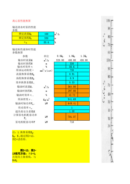
离心泵性能换算输送清水时泵的性能参数额定流量Q 0400m 3/h额定扬程H 0330mη080.6%输送粘性液体时性能参数换算参数单位0.8Q 0 1.0Q 0 1.2Q 0输水时流量Q m 3/h 输水时扬程H m 330输水时效率η%80.6原油运动粘度νmm 2/s(cst)流量换算系数K Q 0.91扬程换算系数K H 0.9效率换算系数K η0.53输油时流量Q νm 3/h 364.00输油时扬程H νm 297.00输油时效率ην%42.72原油密度ρνKg/m 3941.69输油时轴功率P m νkW 649.41传动效率ηc 超负荷安全系数K 计算泵电机配套功率P 1kW 701.37泵电机配套功率P kW 注:1.换算系数K Q ,K H ,K η通过图2-12,图2-13查得。
图2-12,图2-13使用方法:从Q-Q 0点处向上做垂线,与H=H 0 (多级泵取单级叶轮的扬程)的斜线相交;然后自交点做水平 线,与所输粘液的运动粘度ν的斜线相交;自交点再做垂线 与各换算系数曲线相交;最后由这些交点做水平线,便可查 出各换算系数。
2.传动效率ηc :a.直接和联轴器传动时ηc取1.0;b.皮带和齿轮传动时ηc可取0.90~0.95。
3.超负荷安全系数K根据表1选取。
4.泵电机配套功率P根据表2选取。
73011.08表1 电机超负荷安全系数K值一览表水泵轴功率≤1.01~22~55~10表2 电机功率分档一览表电压等级0.75 1.1 1.5 2.23430374555759018520022025028031580090010001120125014001.710~251.25~1.15K 水泵轴功率K 1.1~1.081.7~1.525~601.15~1.11.5~1.360~100380V6kV(10kV) 1.3~1.25>1001.08~1.05功率5.57.5111518.5221101321601852002503153554004505005606307101600180020002200功率,kW。
泵计算手册DescriptionThis document briefly describes the pump calculation spreadsheet as developed by W. van Ramshorst. This spreadsheet, with a few small modifications, is now the standard pump calculation tool of LGN. More information in specifying pumps and their associated systems can be found in the Process Standard for pumps.The spreadsheet has 3 sheets i.e., “PumpCalc”, “SystemCurve” and “PumpCurve”. The sheet “PumpCalc” is the main sheet where most of the input is given and the most important results are shown.The sheet “SystemCurve” shows the hydraulic system curves, the control valve curve and the pump efficiency curve. The only required and possible input is the selected control valve size (cell H27) and the constant “Alpha” (cell K44) for the equal percentage control valve calculation. The pump calculations on the main sheet are not influenced, by changes in these values. Only the curves and tables on this sheet are influenced.The sheet “PumpCurve” has only to be accessed in case pump calculations ar e to be performed for an existing pump. The user has to fill in the head and efficiency as function of the flow rate. The data is automatically regressed and the resulting parameters are shown in red on the graphs. The user must copy the parameters to the parameter list below the graph, otherwise the head and efficiency calculations are not correct.The spreadsheet will only use the existing pump data if the user selects the l ast entry in the box “Differential Head” (cell E44 on sheet “PumpCalc”).DefinitionsNormal mass flow Flow rate from material balance for the process design case. Design or Rated flow Flow rate at other operating cases or a required flow rate tocover possible disturbances in the process, typical designfactors are:Feed pumps 1.0Product pumps 1.0 – 1.1Reflux pumps 1.1 – 1.2This factor has to be entered as “Overdesign” (cell J25) on the spreadsheet.Maximum flow Maximum possible flow rate with a wide open control valve.Normally this is 5 – 10% higher than the design flow rate. Minimum flow Flow rate at process turndown conditions, to be specified as“Turndown” (cell H25) on the spreadsheet.Minimum Pump flow Flow rate to avoid vibration, overheating and cavitation of thepump. Normally this is 20 – 30% of the best efficiency of the pump. In the spreadsheet this is fixed at 25%.Control valve Pressure dropThe minimum required control valve pressure drop for the rated flow rate is calculated with the following formulae: dPcv = X * dP friction + Y * dP staticThe factors X and Y depend on the maximum flow (Qm) that should pass through a fully open control valve. For pumps with a rated flow higher than the normal flow (Overdesign > 100%) Qm/Qd is taken equal to 1.05, otherwise Qm/Qd = 1.10.Qm/Qd X Y1.05 0.18 0.041.10 0.39 0.09The minimum control valve pressure drop is 0.7 Bar.The spreadsheet calculates the minimum control valve pressure drop and shows that value under the section “Miscellaneous Data”. The user has to adjust the control valve pressure drop for the normal flow rate until the calculated control valve pressure drop for the rated flow rate is equal or higher as the minimum calculated control valve pressure drop. The used X, Y factors are shown as note 2 in the remark section.It is also possible to modify the X, Y factors to comply with client requirements. This is done by modifying the numbers in the table located at L49.In case of an existing pump the user has to adjust the normal control valve pressure drop until the rated differential head (cell J44) is equal to the number shown in red next to that cell.Differential HeadThe “Pump Differential Head” for the normal flow rate is calculated by subtracting the “Pump Suction Pressure” from the “Discharge Pressure”. At other flow rates the he ad is calculated from a third order polynomal. For an existing pump the parameters of this third order polynomal are regressed (see sheet “PumpCalc”) and for a new pump the parameters depend on the selected pump droop. These parameters are: Droop A B C1.30 -0.1332 -0.0009 -7.0E-061.25 -0.1376 -0.0006 -6.0E-061.20 -0.0501 -0.0013 -2.0E-061.15 -0.0301 -0.0011 -8.0E-071.10 -0.0200 -0.0008 -2.0E-191.05 -0.0176 -0.0002 -2.0E-06The used equation to calculate the pump head at other flow rate is:(Droop*100 + A*x + B*x2 + C*x3) * H norm / 100 + x * (H norm– H normCurve)x Flow / NormalFlow * 100H norm Normal HeadH NormCurve Calculated Normal head with specified parametersNPSHThe available NPSH is calculated from the following formulae: (10200 / Density) * (P a– P v– dP friction) + H l– H pP a Absolute Suction PressureP v Vapor Pressure at Pump SuctiondP friction Suction friction lossesH l Minimum liquid level above gradeH p Pump center line level above gradeThe NPSHA must be 0.6 – 1.0 meter greater then the NPSHR at rated flow conditions. At maximum flow conditions the NPSHA must at least equal to NPSHR.The NPSHR is pump dependent, but the spreadsheet estimates a NPSHR with the following formulae:((rpm/60) * Sqrt(Flow / A) / 100 ) (4/3) + BA is 7.2 for double suction and 3.6 for single suction pumpsB is 1 for normal pumps.B is 2 for pumps with liquids colder than 0°C and/or a pump suction pressure,which is lower as 1 Bara.PowerThe hydraulic power is calculated with:Density * Flow * H / 367,000 (Flow in m3/h)In case of a new pump, the pump efficiency at normal flow rates is derived from the following table:Hydraulic Power (kW) Efficiency (%)0 4010 5020 6050 70100 75500 801000 85The efficiency at other flow rates is estimated with the following formulae:Eff normal * ( 2.6091 * FlowRatio – 0.02 * FlowRatio2 + 4.0E-5 * FlowRatio3Eff normal Efficiency at normal flow rates.FlowRatio Volume Flow Rate / Normal Volume Flow RateThe user can fix the efficiency by filling a number in cell E46. The pump efficiency is then assumed to be constant for all flow rates.The Brake Horse Power is calculated from:Brake Horse Power = Hydraulic Power / EfficiencyShutoff HeadThe shutoff head is the maximum ofThe Normal suction pressure plus the maximum differential pressureorThe suction design pressure plus normal differential pressure The user may deviate from this approach and edit the formulae to comply with client standards.SoundThe sound level in dB(A) is calculated for the normal flow rate only and is a function of the Brake Horse Power:Brake Horse Power (kW) Sound Level dB(A)<12 85<30 74 + 10 * Log(BHP)<400 77 + 8 * Log(BHP)>400 98CV sizeThe Control valve CV is calculated fromFlow / 864.4 * Sqrt(dP rated * Density / 1000)Flow Rated flow rate in kg/hdP rated Control valve pressure drop at rated conditionsThe control valve size is estimated fromSqrt (CV / 0.85 / 12)Based on the assumption that the control valve is 85% open.。
液压泵常用计算公式选
型计算用
Document number【980KGB-6898YT-769T8CB-246UT-18GG08】
液压泵的主要技术参数
(1)泵的排量(mL/r)泵每旋转一周、所能排出的液体体积。
(2)泵的理论流量(L/min)在额定转数时、用计算方法得到的单位时间内泵能排出的最大流量。
(3)泵的额定流量(L/min)在正常工作条件下;保证泵长时间运转所能输出的最大流量。
(4)泵的额定压力(MPa)在正常工作条件下,能保证泵能长时间运转的最高压力。
(5)泵的最高压力(MPa)允许泵在短时间内超过额定压力运转时的最高压力。
(6)泵的额定转数(r/min)在额定压力下,能保证长时间正常运转的最高转数。
(7)泵的最高转数(r/min)在额定压力下,允许泵在短时间内超过额定转速运转时的最高转数。
(8)泵的容积效率(%)泵的实际输出流量与理论流量的比值。
(9)泵的总效率(%)泵输出的液压功率与输入的机械功率的比值。
(10)泵的驱动功率(kW)在正常工作条件下能驱动液压泵的机械功率。
液压泵的常用计算公式见下表:
液压泵的常用计算公式
参数名称单位计算公式符号说明
流量L/min
V—排量(mL/r)
n—转速(r/min)
q
—理论流量
(L/min)
q—实际流量
(L/min)
输入功率kW P
i
—输入功率(kW) T—转矩(N·m)
输出功率kW P
—输出功率(kW) p—输出压力(MPa)
容积效率%η0—容积效率(%)机械效率%ηm—机械效率(%)总效率%η—总效率(%)。
液压泵常用计算公式(选型计算用)液压泵的主要技术参数(1)泵的排量(mL/r)泵每旋转一周、所能排出的液体体积。
(2)泵的理论流量(L/min)在额定转数时、用计算方法得到的单位时间内泵能排出的最大流量。
(3)泵的额定流量(L/min)在正常工作条件下;保证泵长时间运转所能输出的最大流量。
(4)泵的额定压力(MPa)在正常工作条件下,能保证泵能长时间运转的最高压力。
(5)泵的最高压力(MPa)允许泵在短时间内超过额定压力运转时的最高压力。
(6)泵的额定转数(r/min)在额定压力下,能保证长时间正常运转的最高转数。
(7)泵的最高转数(r/min)在额定压力下,允许泵在短时间内超过额定转速运转时的最高转数。
(8)泵的容积效率(%)泵的实际输出流量与理论流量的比值。
(9)泵的总效率(%)泵输出的液压功率与输入的机械功率的比值。
(10)泵的驱动功率(kW)在正常工作条件下能驱动液压泵的机械功率。
液压泵的常用计算公式见下表:液压泵的常用计算公式参数名称单位计算公式符号说明流量L/minV—排量(mL/r)n—转速(r/min)q—理论流量(L/min)q—实际流量(L/min)输入功率kW Pi—输入功率(kW) T—转矩(N·m)输出功率kW P—输出功率(kW) p—输出压力(MPa)容积效率% η0—容积效率(%) 机械效率% ηm—机械效率(%) 总效率% η—总效率(%)(注:专业文档是经验性极强的领域,无法思考和涵盖全面,素材和资料部分来自网络,供参考。
可复制、编制,期待你的好评与关注)。
计量泵转数n的计算公式可以根据泵的排液量和排液时间来计算流量。
排液量可以通过泵的几何参数和工作状态计算得出,而排液时间可以通过泵的转速和排液量计算得出。
将排液量除以排液时间,即可得到泵的流量。
例如,假设计量泵的转速为1450转/分钟,每转排量为6毫升,那么在1分钟内,该泵可以排出的液体量为:1450(转/分钟)* 6(毫升/转)= 8700毫升/分钟。
因此,如果需要泵送5升液体,则需要运行的时间为:5000毫升 / 8700毫升/分钟 = 0.57分钟。
需要注意的是,不同的计量泵可能有不同的排量和转速范围,因此在选择和使用计量泵时,需要根据具体情况进行计算和调整。
1.泵入口侧容器最低压力90kPaA1'.由任何原因引起的超压(最高液位)0kPa2.容器压力90kPaA正常流量 Vn18m3/h密度 D1026kg/m
3
9.=7*D/101.97静压头(+)或上吸为(-)-3.019kPa3.泵入口处的液体蒸汽压0.1kPaA流量安全系数M1.3粘度1.65mPa.s
10.=1+986.981kPaA4.=(2-3)*101.97/D8.9m设计流量 Vd23.4m3/h温度200C
11.正常流量下管道阻力5kPa12.=11*M2 设计能力下管道阻力8kPa5.绝对最低液面标高0.0m 泵在设计能力下的:
13.正常流量下换热器阻力0kPa14.=13*M2 设计能力下换热器阻力0kPa6.泵的基础标高0.3m吸入压力 1679kPaA
15.=10-11-13正常流量吸入压力81.981kPaA16.=10-12-14 设计能力下吸入压力78.531kPaA7.=5-6 静压头(+)或上吸为(-)-0.3m排出压力 41239kPaA
8.=4+7 有效压头8.6m园整压差 42,430kPa
22.泵出口侧容器压力90kPaA17.=12*101.97/D设计能力管阻力 0.8m有效的NPSHa 217.3m
23.静压头损失1m31.=26*M20kPa18'.往复泵加速度损失0.0m最大吸入压力4687kPaA
24.=22+23*D/101.97 总不变压力100.06kPaA32.设计能力下干净炉子的安全裕量-kPa18.=14*101.97/D 换热器阻力降0.0m
25.孔板损失0kPa33.设计允许结焦时阻力降(正常为0)-kPa19.=8-17-18-18'有效NPSH7.8m
管道直径管道等级法兰面
26.正常流量下干净炉子的阻力降0kPa34.=(25+29+30)*M220.NPSH的安全裕量0.5m
吸入---
27.干净炉子阻力降的安全裕量0kPa其它设备与管道的阻力降-kPa21.=19-20 泵汇总表有效NPSHa7.3m
排出---
28.正常流量下允许结焦运行时阻力降0kPa35.=31+32+33+34有炉子回路总阻力-kPa
29.其它设备与管道的阻力降0kPa调节阀的规格和型式:-泵的最高操作温度450C
30.正常流量下管道阻力50kPa34.=(25+29+30)*M285kPa调节阀设计流量:-m3/hC值:-最大吸入压力 46.=10+1'87kPaA
36.=25+26+27+28+29+30总可变阻力50kPa37.=34或35 总的可变阻力85kPaAA40A=0.1336566*D*(Vd/C)2-kPa最大关闭压力47A。=46+[42*压力升高%+100%]:
38.=24+36150.06kPa39.=24+37185kPaABBCc=0.36559*Vn*[D/45]1/2-估算大多离心泵在憋压时升高%=20%279kPaA
45.=44-38 调节阀91.92kPa40.=41-39 (调节阀最小压差: )54kPaCCCc/C [应为0.25至0.8]-泵关闭压力(实际升高%=0%)87kPaA
44.=15+42 正常排出压力241.98kPaA41.=42+16 设计排出压力238.53kPaADD45/36 [应为0.43至1.0]-泵的最小压差=AA+39-16106kPa
42.压差(离心泵)160kPa42.压差(离心泵)160kPa为了使调节阀在一定的范围内具有可调性,注:十位数50小于取50,大于50取100
43.正常流量下往复泵或转子泵的压差0kPa43.设计流量下往复泵或转子泵的压差0kPa应保证调节阀有足够的压力降。园整后泵的最小压差42或430kPa
设计流量下吸入管的百米阻力降-kPa设计流量下排出管的百米阻力降-kPa
合同号专 业
第 1页 共 1 页
CONT.No SHEET OF
NMCD201101
工艺
设计阶段初步设计DISP.STAGE审 核
APPD.
CHKD.0TAG No.
TYPE
设备位号PUMP CALCULATION SHEET设 计校 核
P0101
泵型式
DATE图 号DESD.DOCUMENT No.内蒙古轻化工业设计院有限责任公司泵 计 算 表(B) 在设计流量下没有炉子的回路版 次123REV.泵 排 出 条 件(A) 在设计流量下有炉子的回路调 节 阀往 来 关 系泵 吸 入 条 件NPSH 计 算泵 数 据正 常设 计 This document is the property of ICCC. It shall not be reproduced or transfered to any other party without ICCC's permission in written form.晋通化工3000吨/年聚芳硫醚砜树脂材料工业化装置罐区项目名称PROJECT分项名称SUBPROJECT
日 期