《光纤通信》实验4 光纤中的四波混频效应
- 格式:doc
- 大小:542.50 KB
- 文档页数:10
- 1 -光子晶体光纤中飞秒脉冲四波混频的实验研究1耿丹1,杨冬晓1,2,王亮21浙江大学信息与电子工程学系,浙江杭州(310027) 2浙江大学太赫兹技术研究中心,浙江杭州(310027)E-mail :yangdx@摘 要: 本文对通信波段的飞秒脉冲激光在色散平坦光子晶体光纤中四波混频的特性进行了实验研究。
当满足相位匹配条件时,斯托克斯波和反斯托克斯波能从噪声中形成;当泵浦功率增大时,斯托克斯波和反斯托克斯波的功率也随之增大,且二者的波长不变。
关键词:光子晶体光纤 四波混频 斯托克斯波 中图分类号:TP212.141. 引 言光子晶体光纤(photonic crystal fiber ,简称PCF )是近年来出现的一种新型光纤,它具有无限单模传输特性,通过对PCF 的设计可以调节它的色散特性,减少模场面积,增加非线性系数,吸引了人们浓厚的兴趣[1]。
近年来,人们对PCF 中非线性效应进行了较多的研究,包括在PCF 中观察到了超连续谱[2]、利用PCF 制成的全光开关[3-4]、布里渊激光器[5],以及PCF 中的拉曼放大[6-7]、四波混频[8-10]等。
利用参量放大可以做成光参量放大器,原则上只要有合适波长的泵浦,光参量放大器能放大任意波长的信号。
参量放大除了放大信号光之外,还能够产生闲频光,因此,参量放大是频率转换的一种有效方式。
参量放大还有归零脉冲产生、光时分解复用和全光抽样等应用。
近年来,PCF 中的四波混频取得了较大的进展。
2001年Sharping 等人第一次研究了PCF 中的四波混频效应,利用753 nm 波段的纳秒激光泵浦PCF [8];2002年,Kazi 等人利用810 nm 波段的飞秒激光泵浦锥形的PCF [10];2003年,Tang 等人研究了1550 nm 波段的纳秒激光泵浦PCF 参量放大[9]。
为得到高增益、宽带宽、单波长泵浦的光纤光参量放大器,需要高泵浦功率、高非线性系数和低色散斜率的短光纤。
第34卷增刊JOURNAL OF XIDIAN UNIVERSITY V ol.34 Sup.高速光纤传输系统中不同调制码型下的带内四波混频秦 曦, 张 峰, 吕 博, 卢 丹, 陈 明, 简水生(北京交通大学 光波技术研究所,全光网与现代通信网教育部重点实验室,北京,100044)摘要带内四波混频是传输速率大于10Gb/s的光纤传输系统中最主要的非线性效应之一,它对信号传输的影响体现在两方面:使“1”码产生幅度抖动,在“0”码处产生“影子”脉冲。
其结果是使信号眼图恶化,误码增加。
从物理本质出发,详细的分析了带内四波混频的产生机理,在此基础上,比较了归零码、载波抑制归零码和交替反转码对“影子”脉冲的抑制能力,结果表明:交替反转码对“影子”脉冲的抑制作用最好,载波抑制归零码居中,归零码抑制能力最弱。
通过数值仿真对理论分析的结论进行了验证。
所得的结论可作为设计高速光纤传输系统的参考。
关键词光纤传输系统;带内四波混频;载波抑制归零码;交替反转码;影子脉冲中图分类号:TN929.11 文献标识码:A文章编号:1001-2400(2007)S1-0043-04 Intrachannel four-wave mixing in high speed optical fiber transmission systems withdifferent modulation formatsQIN Xi, ZHANG Feng, LüBo, LU Dan, CHEN Ming, JIAN Shui-sheng(1. Key Lab of All Optical Network & Advanced Telecommunication Network of EMC, Beijing Jiaotong University, Beijing 100044, China; 2.Institute of Lightwave Technology, Beijing Jiaotong University, Beijing 100044, China)Abstract:Intrachannel Four-W ave Mixing (IFWM) is one of the most important nonlinear effects in optical fibertransmission systems with a bit rate higher than 10Gb/s. It induces the timing jitter to ‘1’ pulses and produces ‘ghost’ pulsesto ‘0’ pulses, which will worsen the eyediagram and result in a bit error. In this paper, the mechanism of IFWM is analyzedin detail. And the abilities of return-to-zero (RZ), carrier-suppressed return-to-zero (CSRZ), and alternate mark inversion(AMI) to suppress the ‘ghost’ pulse induced by IFWM are theorectically compared. The results show that the AMI code isthe most effective one in suppressing the ‘ghost’ pulse, CSRZ is the moderate one, and the RZ code is the poorest one.Numerical simulation is utilized to validate the conclusion. The conclusion is a good reference for designing of high speedoptical fiber transmission systems.Keywords: optical fiber transmission system; intrachannel four-wave mixing; carrier-suppressed return-to-zero; alternatemark inversion; ‘ghost’ pulse在单信道传输速率低于10Gb/s时,自相位调制(Self-phase Modulation, SPM)、交叉相位调制(Cross-phase Modulation, XPM)和四波混频(Four-wave Mixing, FWM)是最主要的非线性效应,而当单信道传输速率高于10Gb/s,特别是高于40Gb/s后,带内交叉相位调制[1](Intrachannel Cross-phase Modulation, IXPM )和带内四波混频[1](Intrachannel Four-wave Mixing, IFWM)取代XPM和FWM,成为限制高速光纤传输系统的最主要因素,其中,IXPM效应引起相邻脉冲间的时间抖动,IFWM则引起“1”脉冲的幅度抖动,并且会在“0”脉冲处产生“影子”脉冲(即所谓的‘ghost’pulse),它们都会引起眼图的恶化,增加误码率。
AbstractFiber optical parametric amplifiers (FOPAs) are optical devices depending on theχwhich need one or two pumps. The nonlinear response of the third-order susceptible (3)pump wavelengthλis generally tuned near the zero dispersion wavelength 0λas well as 0the phase matching condition being matched.The major advantages of FOPAs are broad bandwidth, high signal gain, able to operate at arbitrary center wavelength, idler generation(good for wavelength conversion), high-speed optical signal processing and so on .In this paper, we conduct a deep theory and experiment research concerning the parametric gain ,gain saturation, signal gain spectrum improvement and the suppression of degenerate four-wave mixing in non-degenerate optical parametric amplification. The structure of this paper is as follows:(1) Research of basic theory of fiber amplifiers. With Maxwell equations we get Nonlinear Schrodinger Equation(NLS) which describes the evolution of the lightwave in the FOPA.(2) Research of the gain parametric coefficient.We acquire the analytical expression of the parametric gain coefficient from the small-signal model, and discuss the maximum value of the parametric gain coefficient and the gain bandwidth from both one pump and two pumps. The conclusion is that the maximum value of the parametric gain coefficient and the gain bandwidth relate to wavelengths and power of the launched pump lightwave and signal lightwave.(3) Research of gain saturation characteristics of optical parametric amplifiers.In this paper, we mainly study gain saturation characteristics in non-degenerate optical parametric amplifiers by Finite Difference Time Domain method solving Nonlinear Schrodinger equation, and the conclusion is that under the same condition, the gain saturation value of double pumping optical parametric amplifiers is greater than that of a single pumping one, and gain saturation value increases with the power of launched pumping lightwave increasing, as well as decreasing with the power of launched signal lightwave increasing(4) Research into suppression of the idler in the degenerate four-wave mixing which takes place in non-degenerate optical parametric amplifiers. Due to the four-wave mixing effect which weakens the capability of the signal light amplifying in a non-degenerate optical parametric amplifier process happens between two high pumping source .In this article,we have done some researches on suppression of the idler in the degenerate four-wavemixing and the conclusion is that degenerate four-wave mixing effect can be completely suppressed by choosing proper pumping lightwave wavelength.(5) Research of the signal gain spectrum .We have analysed the model that adding a section of dispersion compensation fiber (DCF) connects to the tail of the high nonlinear fiber to improve the signal gain spectrum. Meanwhile ,we get an analytical expression of the output signal lightwave power led by the Nonlinear Schrodinger equation. On this basis ,we then have furtherly analysed another model of periodically inserting DCF into HNLF to improve the signal gain spectrum, which could be used as a pectination filter.(6) Conducting an experimental research on broadband tunable wavelength conversion based on the fiber optical parametric amplifiers. The signal wavelength is fixed nearby the zero dispersion wavelength, and the high power pump lightwave acts as a pumping source. When the wavelength of the continuous tunable laser is adjusted towards the long wavelength direction, the wavelength of the new born idler is automatically adjusted towards the short wavelength direction.Key words:gain coefficient gain saturation parametric amplifierfour-wave mixing finite difference time domain独创性声明本人声明所呈交的学位论文是我个人在导师指导下进行的研究工作及取得的研究成果。
三次谐波与四波混频(2013年12月31)摘要:讨论了各向同性介质中的三阶非线性过程,以及四波混频和它的特殊情况。
关键词:三阶非线性过程,四波混频。
一、 各向同性介质中的三阶非线性过程只有不具有中心对称性的介质或者各向异性介质才具有二阶非线性,但是所有介质都存在着三阶非线性。
一般(3)χ比(2)χ小得多,故三阶效应要比二阶效应弱得多。
在三阶非线性现象中,也存在着光与介质不发生能量交换,而参与作用的光波之间发生能量交换的非线性效应,这被称为波动非线性效应。
设输入光场()E t 是由沿z 方向传播的三个不同频率的单色光场组成312123().i t i t i t E t E e E e E e c c ωωω---=+++ (1.1) 相应的各向同性介质中的三阶非线性极化强度为(3)(3)30()()P t E tεχ= (1.2) 将式(1.1)代入式(1.2),可见(3)()P t 是具有不同频率的(包括零频)的各项极化强度之和,可以写成(3)()()n i t n nP t P e ωω-=∑ (1.3)式中n 取±,负号表示复数共轭量,包括极化强度的各种频率成分:11211231231200,0,3,,,2ωωωωωωωωωωωω+++-+等。
这些频率项分别表示三次谐波、四波混频、相位共轭、光克尔效应、自聚焦、饱和吸收、双光子吸收、受激散射等三阶非线性光学效应。
三倍频效应是频率为ω的光场入射介质产生频率为3ω光场的过程,其极化强度为(3)(3)30(3)(3;,,)()P E ωεχωωωωω= (1.4) 这里D=1. 很少有晶体能实现三倍频的相位匹配,而且输入激光的强度往往受到光损伤的限制。
气体激光损伤极限强度比固体要高几个数量级,研究表明碱金属蒸汽在可见光区极化率(3)χ有很强的共振增强,因此具有较强的三倍频效应。
以功率比表示的三倍频的转换效率为222(3)223243039()sin ()2P P L kL c P c n n S ωωωωωωηχε∆== (1.5) 定义相干长度c c /,L=L kL /2/2c L k ππ=∆∆=当时,,三倍频效率很快下降;当0k ∆=,相位匹配,有最大的转换效率。
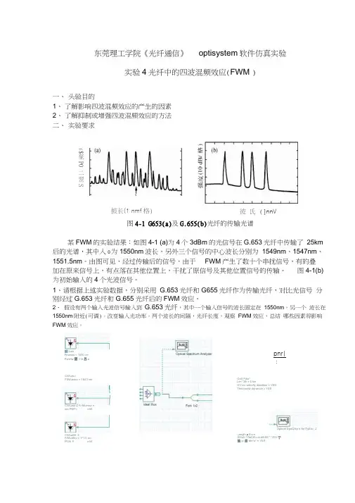
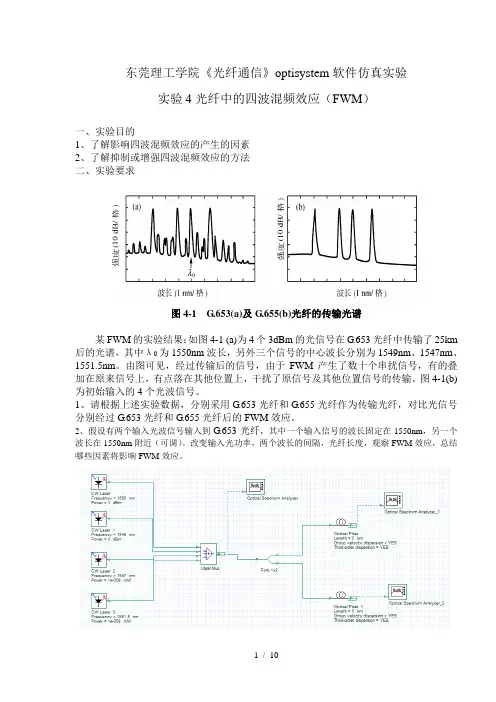
东莞理工学院《光纤通信》optisystem软件仿真实验实验4光纤中的四波混频效应(FWM )一、头验目的1、了解影响四波混频效应的产生的因素2、了解抑制或增强四波混频效应的方法二、实验要求图4-1 G653(a)及G.655(b)光纤的传输光谱某FWM的实验结果:如图4-1 (a)为4个3dBm的光信号在G.653光纤中传输了25km 后的光谱,其中入0为1550nm波长,另外三个信号的中心波长分别为1549nm、1547nm、1551.5nm。
由图可见,经过传输后的信号,由于FWM产生了数十个串扰信号,有的叠加在原来信号上,有点落在其他位置上,干扰了原信号及其他位置信号的传输。
图4-1(b)为初始输入的4个光波信号。
1、请根据上述实验数据,分别采用G.653光纤和G655光纤作为传输光纤,对比光信号分别经过G.653光纤和G.655光纤后的FWM效应。
2、假设有两个输入光波信号输入到G.653光纤,其中一个输入信号的波长固定在1550nm,另一个波长在1550nm附近(可调)。
改变输入光功率,两个波长的间隔,光纤长度,观察FWM效应,总结哪些因素将影响FWM效应。
訥LawFnwwrw = 1550 nmPonHw 團3 id 呂eCWLaw IFfWluencv = 1&43 nmCWLase Z Fr-Muencv =nm PWF= mWCWLaSfi- 3FrMueflcv = 1^1.5 wnP GW =mWpnr|:Os® Fibe*Le<*3th = 5 kmG TDUD webcfty ditwrtkwr = VESThird-ordw diipwcton » YESOptical SpoQtryrn An?}yEar_JLength ■ 5 kmStSuU YfibCiEv dLbWliW * YES 亍恤gr曲drs^s^ = YES披长(1 nmf格)($至P0二翌S彼氏(]nnV格)图4-2 仿真实验系统搭建三、思考题:1、G653光纤有什么缺点?为什么要研制G.655光纤?G.655光纤有什么优点?2、如何抑制光纤中的FWM 效应?附录:计算并输出G.653 或G.655 光纤的色散文件clear all ;close all ;WL=linspace(1450,1630,1801);S0=0.06;WL0=1550;D=S0*(WL-WL0); %G.653%S0=0.0467;WL0=1480;D=S0*(WL-WL0);%G.655figure(1)plot(WL,D, 'k' );hold on ; plot(WL,D*0, 'k' );hold on;axis([1450,1630,-20,20]);WL=WL';D=D';da=[WL D]save E:\G652.txt -ascii daLayout 1 Pmr ametersma1: L^belt Layout 1Simulation Jsignal& Spatial effects Noise Signal tracingwir-inMimr —imiMir-immireiimi ■—NameValueUnits ModeSimulation window Set bit rate: NormalReference bit rateNarmal Bit rale40000000000 B its/sNarmatTime window 3 2e-009NcrmetSample rate25COOOO(K>OOCOHzSequence length 128 Bits NormaiSamples per bit 64 NormalHumber of samples8192^formalAdd Paran... I Remove Pai EditPar^m.CW LaserFn&auency = l&M nmPaw® 工 3 dBm Optical Sp*ctnjm AfL>lyz«fOpbcaJ SfNMtrum Ailsyte r_ICWUMf 1Fiwwn^v = 1543 門仃Pcwef = 3 dBm CW laser 2 FrficnuerK^ = 1M7 fin Fdw«f ■舌呂盼□is 弊阿册 da EI 1PNsrn ErieIJ5«f def Opt»»i FfceJ- 1 OptieaJ Ffe&r U34* d£lmd 阻8itnoe 寓上骨暨比件gib ■■ YES Langth * 25 km人如叼仙=02 dEk'km -SrouD veUcWydwerskxn = YES ThinS-oraer d«sp&f&en = YESDi wnififi fte fi>™ > E 2an^^ Fia-tSH--A FiS tS»^ +M53 Ddl 阳 I HuxNumber 白IT 注“ f^ru ■ 4CWU HT 3FiWLienw = 15&1.5 nm Pawe< 二舌 dBmr&j 『S +EJIBNS waveiengih = YES Length = 2S> km AitcfiuJiEivi > 0.2 dB.km 怎gup vtlfe^V diH<i>ion^ Thrrd-flnfer 中牙 Derfiipn = ¥ DtsaersioH data hw = Fr DfcensKTi he 那a 他=Opttal Specuum Anayisf^G.653:nRx=・pc•■匸Optical Spectrum AnalyzerDbl 亡be* On Objects to open properties. M ME Objects- with Mouse Drago.1.54? 1.S5? 1.56?bUnur-l^nxri'h FmlsampledParafnerteroedl<DOptical Spectrum Analyzer_1Dbl Cbck. On Objects, to open praperties. Move Objects- wrth Mouse Drag1.55?lATauv^^nrn1>lh FmlG.655:B Optical Spectrum Analyzer□bl Click On Objeds to 口“口propcrtM^ Move Objects with Mouse Draywfujgs.■■搖@paldEspissMEss誰口Ngffl3Jem.1.54 ? 1.66?Optical Spectrum Analyze^Dbl Clck On Objeds to open pro perl its IM QVU Obit dis wih Mouse iDrng2:CWLarsef iFi»qu»n 匚 y ■ 154 禺 nm Pflwtf - 3(1)改变波长间隔: 1545:目Optical Spectrum AnalyzerObi Cfck On Objects 1Q 叩un propertes. M-ovc Object® with Mouse Drag电Optical Spectrum Analyzer_1Obl 匚Id On Digels to* open proper1^& Move Objects M&use Drsg1.54? 1.55T 1.56?Wml^ngih (mJ1542 :Optical Spectrum AnalyzerOtriClck 5 ObjBizts 1o ope<i pro periled Move 口 bjects. with Mouse Drag旦Optical Spectrum AnalyzeMOU Click On Objects 1D open propertie-a Move 0 bjecU wth M&u&e DnI 如1 MuXNurnittr 护f inpirt p«rtF - 2CWLucfFreaij&fw = iKO nfin Powvr ■: H dB^nCptiud FiberU&&r defirted ^lerence 椚”谢《科出=YES L«narth = 25 kmA IUHU ALW X D2 d&'km G*WP v^isM^iY 段= YiES Firnlkirde! diaperMDH - YES Or5aer«n ctilU tvi&e = F#W 他D- sKubn Hit ra™ ■ E 201*谟咒姜亘哼空冬上苗叵歧真鱼4■光岂卡曲FWUi£兰GS 刃.txtp 鲁ugtaufj^dgw(E B ZJKIADd吊E - 8-I ffi x J t m Q d■1 54 ?1.55?Wavelength tml1 55 ?1.S?Wavelenoth 4mk™l Optical Spectrum AnalyzerOWiCicH Oo Objects ten open propen卿.⑷叫Objects wth 如站趺Ora j兰Optical Spectrijm Analyzer_1EHbl Cick On Obfecta B open propcrtes. M OVE Objects wfth hlDU>s>e 1520:1515:<DfA1.S3? 1 54? 15S7 1 56?Ulm -1 ― iwliBi. ■Tan』-:_■亠-:-■-:二■_:-■0£>s-耳OB—宅caprwl&od1.51 ? 1 .52? 1.53? 4 £4 ? 1.55 ? 1.58?z□寸・oErs1 49 ? 1.51 7 1 S3? 155? 157?sa o3时*一LIRBI X W JL umv *fParamelerlMd石Ns—og・rEHsJkrnod.49? 1 Si ? 1.S3? J.55 ?WAveleiHflh (m)(2)改变光功率:10dbm:1 56?54?5dbm:1.54? 1.55 7 1.56-10dbm:i .55?s.官BPrEQd1 56"egDS®I9话MdSNN-r¥09・wfflprmdd-20dbm:-50dbm:1.54?1:55?pOJeg-ELU巴Ed2選Ns1.56?(3)改变光纤长度:50km:k mINoise Param eterliedJAll Noise Parametrized S Pouvtr (dBm)甸llNotse Parametrized S :Powr(diBm)i-90 ・巾 -50・30-10p a rM s M u d匹£ ①且昼.54 ? 1 .55? 1.560.2km: 1.54?1.55 ?1 .SB?ULhM-ukl^uuvHi divn'l莎至一一站毎UJsEd 需一ons1.54 ?1.55 ?1 .56MrflA-lAlAJWTttl dml。
东莞理工学院《光纤通信》optisystem软件仿真实验实验4光纤中的四波混频效应(FWM)一、实验目的1、了解影响四波混频效应的产生的因素2、了解抑制或增强四波混频效应的方法二、实验要求图4-1 G.653(a)及G.655(b)光纤的传输光谱某FWM的实验结果:如图4-1 (a)为4个3dBm的光信号在G.653光纤中传输了25km 后的光谱,其中λ0为1550nm波长,另外三个信号的中心波长分别为1549nm、1547nm、1551.5nm。
由图可见,经过传输后的信号,由于FWM产生了数十个串扰信号,有的叠加在原来信号上,有点落在其他位置上,干扰了原信号及其他位置信号的传输。
图4-1(b) 为初始输入的4个光波信号。
1、请根据上述实验数据,分别采用G.653光纤和G.655光纤作为传输光纤,对比光信号分别经过G.653光纤和G.655光纤后的FWM效应。
2、假设有两个输入光波信号输入到G.653光纤,其中一个输入信号的波长固定在1550nm,另一个波长在1550nm附近(可调)。
改变输入光功率,两个波长的间隔,光纤长度,观察FWM效应,总结哪些因素将影响FWM效应。
图4-2 仿真实验系统搭建三、思考题:1、G.653光纤有什么缺点?为什么要研制G.655光纤?G.655光纤有什么优点?2、如何抑制光纤中的FWM效应?附录:计算并输出G.653或G.655光纤的色散文件clear all;close all;WL=linspace(1450,1630,1801);S0=0.06;WL0=1550;D=S0*(WL-WL0);%G.653%S0=0.0467;WL0=1480;D=S0*(WL-WL0);%G.655figure(1)plot(WL,D,'k');hold on;plot(WL,D*0,'k');hold on;axis([1450,1630,-20,20]);WL=WL';D=D';da=[WL D]save E:\G652.txt-ascii da1:G.653:G.655:2:(1)改变波长间隔:1545:1542:1520:1515:(2)改变光功率:10dbm:5dbm:-10dbm:-20dbm:-50dbm:(3)改变光纤长度:50km:10km:5km:1km:0.2km:。
一、填空题1.光纤通信中所使用的光纤是截面很小的可绕透明长丝,它在长距离内具有(束缚)和传输光的作用。
2.光具有波粒二像性,既可以将光看成光波,也可以将光看作是由光子组成的(粒子流)。
3.波动光学是把光纤中的光作为经典(电磁场)来处理。
4.光纤色散是指由于光纤所传输的信号是由不同频率成分和不同模式成分所携带的,由于不同频率成分和不同模式成分的传输速度不同,从而导致(信号畸变)的一种物理现象。
5.在数字光纤通信系统中,色散使(光脉冲)发生展宽。
6.波导色散主要是由光源的光谱宽度和光纤的(几何结构)所引起的。
7、光纤的非线性可以分为两类,即受激散射效应和(折射率扰动)。
8.当光纤中的非线性效应和色散(相互平衡)时,可以形成光孤子。
9.单模光纤的截止波长是指光纤的第一个(高阶模)截止时的波长。
10.单模光纤实际上传输两个(相互正交)的基模。
11、光纤通信是以(光波)为载频,以光纤为(传输媒介)的通信方式。
12、目前光纤通信在(1550nm)波段附近的损耗最小。
13、(数值孔径)表征了光纤的集光能力。
14、G.653光纤又称做色散位移光纤是通过改变折射率的分布将(1310)nm附近的零色散点,位移到(1550)nm附近,从而使光纤的低损耗窗口与零色散窗口重合的一种光纤。
15、G.655在1530-1565nm之间光纤的典型参数为:衰减<(0.25)dB/km;色散系数在(1-6ps/nm·km)之间。
16、克尔效应也称作折射率效应,也就是光纤的折射率n随着光强的变化而变化的(非线性)现象。
17、在多波长光纤通信系统中,克尔效应会导致信号的相位受其它通路功率的(调制),这种现象称(交叉相位调制)。
18、当多个具有一定强度的光波在光纤中混合时,光纤的(非线性)会导致产生其它新的波长,就是(四波混频)效应。
19、G.652光纤有两个应用窗口,即1310nm和1550nm,前者每公里的典型衰耗值为(0.34dB),后者为(0.2dB)。
基于纳米材料涂覆的光纤四波混频实验研究张扬;段志会;王芳【摘要】四波混频(Four-Wave Mixing,FWM)在现代光通信领域具有非常重要的应用价值,是光波长变换和波分复用的关键技术之一.利用一种新型的碳纳米管涂覆倾斜光纤光栅构建全光纤四波混频转换器,并针对该结构展开系统参数特性研究实验.针对输入倾斜光纤光栅的不同泵浦光功率和不同的泵浦光波长这两个重要参数,我们进行了四波混频效率的实验设计.通过对实验结果进行分析,可以得到实验结论:泵浦光的波长对FWM的转换效率在一定范围的影响较小,而单泵浦光的光功率对FWM的影响成二次函数的关系.通过新型全光纤四波混频实验,使学生了解全光纤四波混频的基本工作原理,激发学生对光纤通信的兴趣.【期刊名称】《实验室科学》【年(卷),期】2017(020)005【总页数】4页(P24-27)【关键词】四波混频;倾斜光纤光栅;碳纳米管【作者】张扬;段志会;王芳【作者单位】大连理工大学物理与光电工程学院, 辽宁大连 116024;大连理工大学物理与光电工程学院, 辽宁大连 116024;大连理工大学物理与光电工程学院, 辽宁大连 116024【正文语种】中文【中图分类】TN253四波混频(FWM)效应是一种由介质的三阶极化率所引起的非线性光学效应[1],属于光学混频范畴。
在通信领域,由于四波混频产生杂波对光纤传输通信系统的性能通常会有不利影响,某些时候需要抑制,但同时该现象也是实现全光波长转换的关键技术。
光波长变换功能,即把某一波长光波载运的信息利用四波混频效应变换到另一波长上再被检测装置接收和解调[2-3]。
当入射的两束光波满足相位匹配条件时,通过非线性介质产生四波混频效应,获得四波混频的新生光波可以作为新的载波信号光。
这种光波长变换技术在未来的密集波分复用全光网络中有重要的应用。
本实验主要利用新型的碳纳米管涂覆的倾斜光纤光栅作为四波混频发生器,并研究不同泵浦光波长与功率对FWM转换效率的影响,从而让学生能够了解光通讯关键技术的基本原理。
飞秒激光在双折射微结构光纤中模式控制的四波混频效应的实验研究3胡明列 王清月 栗岩峰 王 专 柴 路 张伟力(天津大学精密仪器与光电子工程学院超快激光研究室光电信息技术科学教育部重点实验室(天津大学),天津 300072)(2004年7月15日收到;2004年12月31日收到修改稿) 利用飞秒激光脉冲在长度为10cm ,包层具有大空气比的双折射微结构光纤中通过高阶模相位匹配的四波混频获得了波长可调谐的反斯托克斯波.实验中脉冲宽度为35fs ,中心波长820nm ,单脉冲能量4n J 的飞秒激光脉冲耦合到长轴直径为5μm ,短轴为416μm 的双折射微结构光纤中.在高阶模传输情况下,通过调制耦合光的偏振方向,获得了具有不同中心波长的反斯托克斯波.通过对比分析,讨论了输入光的偏振态对双折射微结构光纤中高阶模式下四波混频效应的影响情况.理论计算分析很好的解释了实验结果.关键词:微结构光纤,飞秒脉冲激光,四波混频PACC :7820F ,4270Q ,7155J ,3320K3国家重点基础研究专项基金(批准号:G 1999075201,2003C B314904),国家自然科学基金(批准号:60278003)和国家高技术研究发展计划(批准号:2003AA311010)资助的课题.E -mail :huminglie @ 11引言最近的研究表明微结构光纤(microstructurefibers ,MFs )[1—3]在双折射方面表现出很强的优势,通过特定设计的纤芯和包层结构能获得很高的双折射度[4—6],比传统双折射光纤能够高出1—2个数量级.这对某些应用,例如光学陀螺,激光干涉仪,以及在量子光学和光子纠缠态方面的应用具有很重要的价值.这些应用希望光纤在传输光波时不改变它的偏振态.传统的做法是在这些光纤中故意引入大量双折射,使得那些微小的、随机的双折射起伏不会严重影响光的偏振.一种方案是打破圆柱对称性,故意把纤芯或是包层做成椭圆形的结构,它的双折射度B 可达到非常小的程度(B ≈10-6),另一种可代替的方案是利用应力致双折射,使得B 可达到≈10-4.这类光纤通常以其横断面的形状特征而称之为“熊猫”光纤或“领结”光纤.而微结构光纤因其芯层包层所具有的高折射率差能极大地增强双折射度,通过特殊设计能获得比普通保偏光纤高出数量级的双折射度,从而成为该领域研究的热点[7—10].对于双折射光纤,其有效模折射率较小的轴称为快轴,在此轴上光传输的群速度较大.同样的道理,有较大有效模折射率的轴称为慢轴.对于光纤中高阶模相位匹配的参量效应和谐波的产生,人们已作了广泛的研究.最早在多模光纤中观察到高阶模下的位相匹配的是Stolen 及其合作者[11],其报道中斯托克斯波和反斯托克斯波传输在不同的高阶模.从那以后,模式控制的相位匹配参量过程成为产生新光谱的一种有效方式,而微结构光纤在这方面也显示出很强的优势[12—21].就四波混频而言,当净波矢失配κ=0时,参量增益对应四波混频峰值,这里κ可写成如下形式κ=Δk M +Δk W +Δk N L =0,(1)式中Δk M ,Δk W ,Δk N L 分别代表由材料色散、波导色散、非线性效应引起的相位失配.这三项的贡献可以分别写成Δk M =[n 3ω3+n 4ω4-2n 1ω1]Πc ,(2)Δk W =[Δn 3ω3+Δn 4ω4-(Δn 1+Δn 2)ω1]Πc ,(3)第54卷第9期2005年9月100023290Π2005Π54(09)Π4411205物 理 学 报ACT A PHY SIC A SI NIC AVol.54,N o.9,September ,2005ν2005Chin.Phys.S oc.精品文献ΔkN L=γ(P1+P2).(4) 在ω1=ω2的特定条件下,满足Δk=0的实验装置相对要简易一些,此时非线性过程中只牵涉到3个不同频率,被称作部分简并的四波混频.事实上,直接与受激拉曼散射(SRS)类比,ω3处的低频边带和ω4(假设ω3<ω4)的高频边带称为斯托克斯带和反斯托克斯带.为实现相位匹配,三项贡献中至少有一项必须为负.当然在多模光纤中,以不同模式传输的波,可使得ΔkW为负值,从而实现相位匹配.在以前的文章中,我们报道了单模双折射微结构光纤在不同偏振光作用下的四波混频效应[13];本文通过耦合角度控制,在多模微结构光纤中实现了模式控制的相位匹配四波混频过程;而同时基于其纤芯的双折射结构,通过控制输入飞秒脉冲的偏振态以及耦合的高阶模式在可见光波段获得了不同峰值和谱宽的反斯托克斯波.21双折射微结构光纤实验中使用的光纤如图1所示,与高非线性微结构光纤相比该光纤具有较大的纤芯面积,较大的空气比(空气比大于90%),其长轴为5μm,短轴为416μm.为了满足相位匹配,需要让抽运光工作在负色散区.通过数值模拟可得到在忽略偏振下的基模和第一高阶模及其他高阶模的有效折射率,再微分便可得出其色散曲线,计算结果见图2.图2说明基模的零色散点为1122μm,第一高阶模的零色散点为790nm,第二高阶模为730nm.而且实验所用的微结构光纤,受到大空气比的包层结构的影响,其芯层和包层的折射率差较大,传输的光束被完全约束在第一层空气孔中,而第二层空气孔几乎不起作用.在外圈增加空气孔,模拟计算结果得到的有效折射率没有变化,这足以证明上述论点;同时这种大纤芯高折射率差的结构使得这种光纤是多模的,而且由于各个低阶模之间较大的波矢失配而相互之间很难耦合[22].实验中发现只有通过调整耦合光束的入射方向来获得不同的高阶模,而通过弯曲或者缠绕很难获得高阶模.一旦激发出高阶模式,弯曲或者缠绕对高价模的传输影响相当小.而且由于各个模式之间的传输波矢相差很大,因此相互之间不会出现耦合.正是由于其特殊的多模特性,利用这种大空气比的微结构光纤很容易获得多模情况下相位匹配的非线性效应,例如谐波的产生[23]和四波混频等等[24],并且具有较高的转换效率.图1 大空气比双折射微结构光纤端面图2 大空气比双折射微结构光纤不同模式的色散曲线在加入微扰条件下,可以得出在两个相互垂直的偏振态下的零色散点大概有10nm的差异[15].通图3 在中心波长为820nm的飞秒激光脉冲的抽运下,第一高阶模和第二高阶模的位相匹配曲线过计算所得的有效折射率,利用(1)式和能量守恒的条件(2ω1=ω2+ω3)可以计算得出在输入脉冲中心波长为820nm时,位相失配κ的曲线,见图3;从曲线中可以得到在第一高阶模情况下,匹配的反斯托2144物 理 学 报54卷克斯波的中心波长在640nm 左右,而在第二高阶模时,为550nm 左右,与实验结果基本相符.为了方便分析,文中将不同耦合角度下的高阶模式分别简单称为第i 高阶模,i 随耦合角度的增加而递增.31实验结果及其分析实验中使用的光源是自行研制的飞秒激光振荡级系统,输出的最高平均功率可达到117W [25].实验中使用的飞秒激光脉冲宽度为35fs ,中心波长在820nm ,单脉冲能量4n J.使用了40×的耦合透镜输入输出,并采用CC D 监视仪和功率计监控耦合输入和输出的情况.耦合输入透镜前加了一片半波片来控制输入飞秒激光脉冲的偏振方向.输出光通过分束片,一束用来成像在CC D 监视器上,监控输出模式,一束用来测量光谱曲线.输入输出光谱分别由两个光谱仪接收,输入光谱由015%的分束镜分束后由Ocean Optics ,Inc.的S2000光谱仪接收用以实时观测,输出光谱通过ANDO 的AQ6315A 接收,测量精度都设定为5—10nm.而利用由于双折射结构带来色散曲线的变化,通过旋转置于耦合透镜前的半波片或者四分之一波片改变输入光的偏振态,便可图4 输出的高阶模的近场模式以得到不同中心波长的反斯托克斯超矩脉冲. 实验中获得了相互垂直的两种第一高阶模,见图4的A 和B ,模场分布为十分清楚的高阶模式.入射光的入射角度和偏振态对输出模式的强度和模式分布有较大的影响.在一定的耦合入射角下,通过旋转半波片来改变入射线偏光的偏振方向可以使输出模式A 和B 相互变化.通过改变入射线偏光的偏振方向获得的反斯托克斯波(见图5),在偏振方向旋转180°范围内.反斯托克斯波具有两个明显的峰值,分别对应于光纤的长轴和短轴,而且在偏振方向在轴线附近时,对反斯托克斯波影响非常明显.实验中没有中间状态的存在,45°线偏光入射的情况下,没有反斯托克斯波输出,这可能有两种原因,一是大空气比微结构光纤的结构使得高阶模的之间的耦合很难,二是抽运功率不够,难以激发出两种模式的混和态.在分别平行于长轴和短轴时,由于纤芯的双折射结构使得反斯托克斯波的峰值和中心波长都不一样.在偏振方向改变过程中,最大转换效率可达20%左右. 在输入的线偏光平行于快轴时,加入四分之一波片并旋转得到了相似的周期性改变的结果,见图6.从图6中还可以发现获得的反斯托克斯波的光谱图5 在高阶模式A 和B 时,通过半波片改变入射线偏光的偏振方向获得的反斯托克斯波光谱图,0°表示偏振方向平行于长轴明显变得更宽,并且在两个相互垂直的方向上的光谱差别减小,这是由于线偏光通过四分之一波片后形成的椭圆偏光或圆偏光除在长轴和短轴方向上有分量外,在其附近还有其他分量,而这些分量产生的光谱相互错开,叠加后形成较宽的光谱.31449期胡明列等:飞秒激光在双折射微结构光纤中模式控制的四波混频效应的实验研究图6 在高阶模式A和B时,通过四分之一波片改变入射线偏光的偏振态获得的反斯托克斯波光谱图,0°表示四分之一波片的主轴平行于长轴在继续增大耦合入射角的情况下,更高阶的模式便出现了,模场分布如图4的C.同样在改变入射光的偏振态的情况下,输出的反斯托克斯的强度和中心波长都在发生变化,如图7所示.但是同上面情况不同的是,平行于短轴的偏振光入射时,没有另一个垂直状态的模式出现.这可以解释为受到双折射结构的影响,短轴方向的折射率曲线不满足相位匹配条件.在此模式下,偏振方向改变过程中,最大转换效率可达16%左右.图7 在高阶模式C时,通过半波片改变入射线偏光的偏振方向获得的反斯托克斯波光谱图,0°表示偏振方向平行于长轴41结 论利用飞秒激光振荡器输出的纳焦耳量级的飞秒激光脉冲通过长度为10cm双折射微结构光纤获得了转换效率高达20%的反斯托克斯波,并且输出的反斯托克斯波的中心波长和强度可以通过输入脉冲的偏振方向或者传输的模式来调谐.实验中将脉冲宽度为35fs,中心波长820nm,单脉冲能量4n J的飞秒激光脉冲耦合到长轴直径为5μm,短轴为416μm,空气比90%左右的双折射微结构光纤中,通过调制耦合光的偏振方向,以及传输模式,获得了具有不同中心波长的反斯托克斯波.理论计算分析也很好地解释了实验结果.[1]K night J C,Birks T A,Russell P S t J et al1996Opt.Lett.211547[2]Birks T A,K night J C,Russell P S t P et al1997Opt.Lett.22961[3]K night J C and Russell P S t J2002Science296276[4]Ortig osa B A,K night J C,W adsw orth W J et al2000Opt.Lett.251325[5]K erbage C,S teinvurzel A,Hele A et al2002Electron.Lett.38310[6]S teel M J and Osg ood J R M2001Opt.Lett.26229[7]Hansen T P,Broeng J,Libori S E B et al2001IEEE Photon.Technol.Lett.13588[8]K erbage C,S teinvuzel P,Reyes P et al2002Opt.Lett.27842[9]Lehtonen M,G enty Gand K aiv ola L H M2003App.Phy.Lett.822197[10]Hu M L,W ang Q Y,Li Y F et al2004Acta Phys.Sin.534248(in Chinese)[胡明列、王清月、栗岩锋等2004物理学报534248][11]S tolen R H and Leibolt W N1976Appl.Opt.15239[12]Husakou A V and Herrmann J2002JOSA B192171[13]Hu M L,W ang Q Y,Chai L et al2004Opt.Exp.121932[14]Hu M L,W ang Q Y,Li Y F et al2004Opt.Exp.126129[15]Hu M,W ang Q Y,Li Y F et al2004App.Phy.B79805[16]Sharping J E,Fiorention M,C oker A et al2001Opt.Lett.261048[17]Sharping J E,Fiorention M,K umar P et al2002Opt.Lett.271675[18]Hu M L,W ang Q Y,Chai L et al2004Las.Phys.Lett.1299[19]Akim ov D A,Serebryannikov E E,Zheltikov A M et al2003Opt.Lett.281948[20]Vanholsbeeck F,Em plit P,C oen S et al2003Opt.Lett.281960[21]E fim ov A,T aylor A J,Omenetto F G et al2003Opt.Exp.112567[22]M arcuse D1991Theory o f Dielectric Optical Waveguide(Academic,Boston,M ass)[23]Omenetto F G,E fim ov A,T aylor A J et al2003Opt.Exp.11614144物 理 学 报54卷[24]Nikolov N I ,Srensen T ,Bang O et al 2003JOSA B 202329[25]Sun J H ,Zhang R B ,Hu Y F et al 2002Acta Phys .Sin .511272(in Chinese )[孙敬华、章若冰、胡有方等2002物理学报511272]Mode -controlled four -wave -mixing in the birefringentmicro structure fiber by femto second la ser pulse s 3Hu M ing -Lie W ang Qing -Y ue Li Y an-Feng W ang Zhuan Chai Lu Zhang W ei-Li(Ultra fast Laser Laboratory ,College o f Precision Instruments and Optoelectronics Engineering ,Tianjin Univer sity ,Tianjin 300072,China )(K ey Laboratory o f Optoelectronic In formation Technical Science (Tianjin Univer sity ),Ministry o f Education ,Tianjin 300072,China )(Received 15July 2004;revised manuscript received 31December 2004)AbstractBirefringent m icrostructure fibers are shown to allow efficient gereration of anti-S tokes line em ission as a result of four-wave-m ixing in higher m ode by using unam plified fem tosecond T i :sapphire laser pulses.Intense blue-shifted lines with different central wavelength were generated in the high-delta (i.e.high-air filling in the cladding )m icrostructure fiber with axis sizes 510and 416μm by fem tosecond laser pulses with 35-fs in duration ,820nm in central wavelength and 4n J in energy per pulse.Theexperimental result shows that phase-matched four-wave m ixing in higher-order m odes of m icrostructure fibers allows unprecedentedly high efficiencies of anti-S tokes frequency conversion to be achieved for subnanojoule fem tosecond laser pulses.The dependence factor of the four waves m ixing in birefringent m icrostructure fiber is com pared and analyzed.G ood agreement between the theory and experiment is achieved.K eyw ords :m icrostructure fiber ,fem tosecond laser ,four-wave-m ixing PACC :7820F ,4270Q ,7155J ,3320K3Project supported by the National K ey Basic Research S pecial F oundation (NK BRSF )(G rant N os.G 1999075201,2003C B314904),the National Natural Science F oundation of China (G rant N o.60278003),and the National H igh T echnology Development Programme of China (G rant N o.2003AA311010).51449期胡明列等:飞秒激光在双折射微结构光纤中模式控制的四波混频效应的实验研究。
研究生实验报告实验项目名称四波混频特性实验研究课程名称现代物理实验方法(一)姓名学号专业凝聚态物理年级院、所物理学院年月日研究生实验报告评价标准实验目的:有机非线性材料的出现,人们可以在分子的水平上设计材料的结构来得到在特定波长激光照射下具有较大χ(3)的材料。
采用共振型非线性材料介质就可以在较低的泵浦强度下,获得较强的相位共轭波,甚至可以连续工作。
可调谐激光技术的飞速发展也使共振增强很容易在介质中实现,它通过改变输出激光的功率来调节与材料直接的共振关系,使得三阶效应增强。
设有频率为ω的三个波E1(ω,Z)、E2(ω,Z)、E3(ω,Z),作用于非线性介质。
E1和E2为强度接近相等、传播方向相反的两个强泵浦波,E3为与E1和E2成一角度(小于8度)的探测波。
这三个光波在非线性介质中相互作用结果,能产生一频率仍为ω的波E4,称信号波,它与探测波是相位共轭的。
可以证明,在上述四波作用下,信号波的大小与非线性介质的χ(3)和泵浦波E1和E2的强度有关系。
下面我们讨论入射光波是平面波的情况时的耦合波方程。
简并四波混频(DFWM)的结构示意图如下。
其中的非线性介质是透明、无色散的介质,三阶非线性极化率是χ(3)。
图1.简并四波混频的结构示意图在介质中相互作用的四个平面波为E i=E(r)exp[-i(ωt-κi· r)]+ E(r)exp[i(ωt-κl· r)] l=1,2,3,4Word 资料 的倾角,使从激光器出射的光波在各处等高。
然后仔细调节等高的方法是转动反射镜或分光镜,使各个光束能够完全重合,得到的光束共线。
四、为了调节泵浦光或探测光的强度而不改变另外一束或两束光的强度,用减光板调节需要改变的光束,用光功率计记录光强度。
实验结果:1.信号光强度随泵浦光强度的变化2.信号光强度随探测光强度的变化3.信号光强度随探测角度(大)的变化4.信号光强度随探测角度(小)的变化484950515253546000080000100000120000140000160000180000200000B A B891011121314140000160000180000200000220000240000260000BAB。
空频复用光纤中四波混频过程的解析分析方法万峰; 武保剑; 曹亚敏; 王瑜浩; 文峰; 邱昆【期刊名称】《《物理学报》》【年(卷),期】2019(068)011【总页数】9页(P157-165)【关键词】空分复用; 少模光纤; 四波混频; 解析解【作者】万峰; 武保剑; 曹亚敏; 王瑜浩; 文峰; 邱昆【作者单位】电子科技大学信息与通信工程学院光纤传感与通信教育部重点实验室成都611731【正文语种】中文1 引言近年来,波分复用 (wave division multiplexing,WDM)通信系统传输容量已逐渐逼近非线性香农极限[1,2].为满足通信容量不断提高的需求,空分复用 (space division multiplexing,SDM)应运而生,已成为备受关注的技术之一[3−7].SDM主要应用形式是与当前的WDM系统相结合,构成空频复用传输系统,使通信容量得到大幅提升.因此,以少模光纤等为代表的模分复用(mode division multiplexing,MDM)技术成为光通信领域中研究的热点[8,9].利用光纤中各导波模式之间的正交性,可构建MDM传输系统[10].在 WDM 系统中,四波混频 (four wave mixing,FWM)等光纤非线性效应会严重影响通信传输的性能,相关理论不断完善[11].近年来,MDM 系统的非线性效应也开始受到关注.2013年,Mumtaz等[12]建立了少模或多芯光纤中的非线性传输模型,并通过该模型研究了114 Gb/s信号在少模光纤中传输 1000 km 的通信性能.同年,Mumtaz 等[13]和Essiambre等[14]通过实验验证了少模光纤中模间FWM效应,证明在大频率间隔(THz)和较大模式色散条件下也能满足相位匹配条件.文献[15]提出了MDM系统中高斯噪声非线性理论模型,将信道间非线性作用近似为高斯噪声处理,研究非线性对空频复用光纤传输系统的影响.2017年,Trichili等[16]给出了小信号条件下空频耦合模方程的近似解,分析了少模相敏参量放大过程,该理论不适用于抽运消耗的情形.时域光纤非线性演化方程的一般处理方法是采用分步傅里叶方法数值求解,而在准连续波情形下也可以得到解析解[17].解析解能更好地反映非线性过程的参数依赖关系,最近我们给出了单模高非线性光纤中简并和非简并FWM闲频光幅度和相位的统一解析表达式,证明了非相敏放大(phase insensitive amplify,PIA)模式下闲频光相位与输入光初始相位之间的关系,揭示了FWM相位加减混合运算器的工作原理[18].MDM光纤系统的非线性比单模情形复杂,自相位调制、交叉相位调制、四波混频等非线性项的系数均与模场交叠因子相关,目前的理论研究主要集中在数值模拟或基于特定场景的半解析模型上,精确的解析分析方法还未有报道[12,19−22].本文详细推导了空频域FWM耦合模方程的精确解析解,并采用数值方法验证了解析结果的正确性.所得解析解适用于具有抽运消耗的情形,可用于分析WDM,MDM 以及它们的联合复用系统中光纤非线性效应对光场幅度和相位的影响.最后,讨论了解析分析方法在多波耦合方程简化、大规模并行相位运算器设计以及快速非线性补偿等方面的应用.2 理论2.1 空频域FWM耦合模方程利用少模光纤并采用WDM技术,可实现光场的空频复用传输.在单模光纤中,FWM 过程发生在具有不同频率的相同模式之间; 在模式复用系统中,具有相同或不同频率的模式之间也会发生FWM.因此,空频复用系统中的非线性耦合方程会更加复杂.为了使推导过程更加清晰,本文考虑准连续线偏振导波光的非简并FWM过程.空频域复用系统中导波光的光场复振幅 Al (l=1—4)满足如下FWM耦合方程组:式中c为真空中光速,z表示少模光纤的长度;ωl(l=1—4)为各导波光的角频率,导波光之间满足能量守恒关系,即ω4+ω3− ω2− ω1=0 ; 相位失配因子∆β=β4+β3− β2− β1,其中βl (l=1—4)为各导波光的传播常数.归一化横向模场分布Fl,m,n,p(x,y)的交叠积分为式中 n2(x,y) 为光纤的非线性折射率参量,F为归一化模场分布函数.当所有涉及的模场交叠积分均相同,且光频率间隔较小时,非线性系数可以统一表示为γNL≈n2k0/Aeff,此时(2)式可化为单模光纤情形[23],其中 k0 为真空中导波光波数, 将光场复振幅表示为的形式,其中 Pl (l=1—4)为光功率,φl (l=1—4)为各导波光的相位.因此,对复振幅方程(1)式的求解可转换为实数场分量的求解.将复振幅的表示代入(1)式,得到功率演化的方程如下:式中θ=∆βz+φ3(z)+φ4(z)− φ1(z)−φ2(z),且满足关系式中参数 O1,O2,O3,O4 与四个光波的功率、频率分布以及模场归一化交叠积分有关,即.显然,(5)式中的参数包括了多模光纤中不同频率和模式的光场作用,体现了多模光纤中导波光的空域和频域耦合特性.与单模光纤情形相比,多模光纤中四波混频耦合模方程的非线性系数发生了改变,各项的非线性系数之间不再保持固定的大小关系,而是取决于耦合光场的模场分布.(4)式也与单模情形的表达式不同,不能直接利用单模光纤的推导过程进行解析求解,因此这种非线性系数的变化增加了推导解析解的难度.下面,本文通过变量代换方法,将模式和频率的依赖性包含到相关参量中,推导多模光纤中FWM功率和相位的解析表达式.令Pi=ωiQi (i=1—4)和则 (3)式—(5)式可重新表示为式中空频域耦合参量 o1,o2,o3,o4 表示为由(6)式可知,各导波光之间存在如下关系:其中Qi0=Pi0/ωi(i=1,2,3,4) ,与导波光的初始功率有关,q (z) 表示 FWM 的转移能量.q (z) 的物理意义可由(9)式加以分析,即q(z)=∆Qi= ∆Pi/ωi=∆PiTi/(ωiTi)=∆Ei/(2π),其中Ti为光波相位周期,E i=PiTi 为一个周期的能量.由(6)式—(9)式可知,q (z) 满足如下方程:其中为积分常数,由初始输入的各光波功率和相位确定,θ0= φ40+φ30− φ20− φ10 ; 参数K (θ) 是转移能量参数θ的二次多项式,其系数R1—R4由多模光纤的各模场交叠积分和频率共同确定,具体可表示为下面根据(10)式和(11)式求出转移能量参数θ随光纤长度z的变化关系,进而给出功率和相位的解析表达式.2.2 功率的解析解表示由 (11)式可知,f (θ) 是关于转移能量参数θ的四次多项式,在初始条件确定的情况下,可以表示为的形式,其中η1< η2< η3< η4 是满足f (θ)=0 的、依次按照从小到大的顺序排列的四个根,表示f(θ)最高次项的系数.于是(10)式可以进一步表示为式中ξ=sign(sinθ0),依赖于输入光波的初始相位关系.我们的目的是得到输出功率的解析表示,即转移能量参数θ (z) 随长度z演化的表达式.当初始条件给定时,(14)式能够表示为第一类椭圆积分.根据第一类椭圆积分与雅可比椭圆函数s n(µ,k) 之间的互逆运算关系,FWM转移能量参数θ (z) 的解析表达式为[17]其中F为第一类椭圆积分.根据(9)式和(15)式,多模光纤中导波光的功率演化规律可解析地表示为(15)式—(17)式描述了空频复用多模光纤FWM作用中导波光的光功率演化规律,也适用于单模光纤的情形,其中参数η1 —η4 计及了空频耦合作用.根据非简并FWM过程所满足的频率关系ω1+ω2= ω3+ω4,由 (17) 式可知,光波沿光纤传播时P1(z)+P2(z)+P3(z)+P4(z)=P10+P20+P30+P40,即总功率始终保持不变,符合FWM作用过程中能量守恒的条件,一定程度上表明了我们理论推导的正确性.2.3 相位的解析解表示由 (4)式可知,导波光的相位与θ (z) 相关,即相位的解析解可以由θ (z) 的解析式推导得到.为简单起见,本文以闲频光的相位φ4 为例,将 o4 和K(θ)分别表示为o4=A+Bq 和K(θ)=Cq+Dq2的形式,其中 A,B,C,D 由 (8)式、(12)式和 (13)式给出.则相位φ4 的演化方程为式中参数 a,b,c,d 表示如下:(18)式具有如下通解形式[17]:式中积分常数与输入导波光初始相位关系可通过解析方法确定[18],本文将通过数值计算方法得到同样的结果.其中φI 和φΠ 均与导波光的初始条件有关,可用第三类椭圆积分表示为:类似于闲频光相位解析解的推导过程,也可以得到其他导波光相位的解析表达式.(20)式—(24)式给出了多模光纤中导波光场相位演化的解析解,尽管形式上与单模光纤的解析解类似,但其中涉及的诸多参量如 A,B,C,D 以及η1 —η4 等有所不同. 需指出的是,上述相位的解析解是在θ (z) 单调区间内得到的.事实上,随着光纤长度z的增加,θ(z)的演化具有周期震荡特性,在(10)式符号改变的位置θ (z) 的单调性也发生改变,此时相位解析解出现奇异 (相位跳变).此外,在 z=0 的初始位置,由于θ (z)=0,当没有闲频光输入时f (θ)=0,相位的解析解也存在奇异性.因此,需单独分析各单调区间的情况,并考虑θ (z) 周期变化对相位的累积影响,有关相位的完整表示在文献[17]中已有详细的讨论.3 解析解的验证下面利用解析解来分析多模光纤中非简并FWM过程,并采用数值方法直接对空频复用FWM耦合模方程(1)式进行求解,来验证上述解析解的正确性.令两个抽运光的频率为 f1 和 f2,探测光为 f3,产生的闲频光频率为 f4,它们的模场分布对应于两个模群的三个线偏振模 LP01,LP11a 和LP11b,具体的模场分布和频率分配如图1所示.结合文献[9,24]给出的少模光纤的参数,选择参考频率 f0 为 194.81 THz,传输光纤长度为 4.5 km; 简并模 LP11a 和 LP11b 具有相同的传播常数,差模群时延对应的色散参量为并且假定所有模式具有相同的色散斜率.对(1)式进行求解,首先要知道导波光场的交叠积分 flmnp 和相位失配∆β.文献[9,24]已给出模场归一化交叠积分的参数 flmnp/fLP01,如表1所列,其中 fLP01 为LP01 模的交叠积分.下面通过优化导波光的频率分布,尽可能满足相位匹配条件∆β≈0.选择参考频率 f0=f1,则相位失配因子∆β 为图1 非简并FWM过程中导波光的模式与频谱分布Fig.1.Mode and frequency distribution in the non-degenerate FWM process.根据 (25) 式,可画出相位失配随∆f1 和∆f2 变化的情况,如图2 所示.优化频率参数∆f1 和∆f2的取值,可使相位匹配失配| ∆β| 取到最小.由图2可知,| ∆β| 对∆f2 的改变更加敏感.选择∆f1=0.13 THz和∆f2=0.33 THz,使| ∆β|=0.则参与FWM 过程的导波光频率为 f1=194.81 THz,f2=195.14 THz,f3=194.68 THz,f4=195.27 THz.根据上述计算参数,用四阶龙格库塔法对(1)式进行数值求解[25],相同参数也代入解析式(15)式—(17)式和(20)式—(24)式,分别得到闲频光的功率和相位随长度z的变化曲线,如图3所示,其中抽运 1的功率为 0.5 W,抽运2的功率为0.35 W,输入探测光功率分别为 0.01,0.05 和 0.1 W.由图3(a)可知,闲频光输出功率的解析解和数值计算结果完全相同,探测光输入功率越大,输出闲频光功率达到饱和所需的光纤长度越短.再结合图3(b)可知,在功率单调变化的区间内,闲频光相位的解析解与数值结果也非常符合,探测光输入功率越大,相位随光纤长度的变化也越大.由图3(b)可知,无闲频光输入时,相位在光纤输入端出现了跳变,计算时闲频光功率取了一个很小的值(如10–10 W).实际上,由于噪声的存在,闲频光输入会从噪声中产生,解析解的条件自动得到满足,因此在应用中并不会受到限制.总之,在解析式的适用范围内,本文得到的解析解与数值结果完全一致.表1 模场的归一化交叠积分参数Table 1.Normalized overlap integral parameters of mode fields.模场分布 flmnp/fLP01/arb.units 4束光都为LP01模 1.000 4束光都为LP11a或LP11b模 0.747 2束光为LP01模、2束光为LP11a或LP11b模 0.496 2束光为LP11a模、2束光为LP11b模 0.249图2 相位失配因子对∆f1 和∆f2 的依赖Fig.2.Dependency of phase mismatching factor on ∆f1 and ∆f2.图3 解析解与数值结果的比较 (a)闲频光功率; (b)闲频光相位parison of analytical and numerical results:(a) Idler output power; (b) idler output phase.上述结果表明,合理设计光纤结构和优化输入参数,少模光纤中仍可发生高效的模间FWM,同时实现模式和波长转换功能.4 解析分析方法的应用与数值计算方法相比,解析分析方法更加便捷.本文给出的空频复用FWM解析解适用范围更加广泛,可快速分析少模光纤中的FWM效应,也可以用于拟合模场交叠积分等.下面讨论解析解在多波耦合方程简化、大规模并行相位运算器设计以及快速非线性补偿等方面的新型应用.4.1 多波耦合项的选择在级联FWM中,特别是在空频复用多模光纤中,多组FWM过程可能同时发生,需用多波耦合方程组加以描述.每个耦合方程对应一个特定模式和频率的光波,并涉及与其他导波光的FWM耦合项,FWM耦合项数随着导波光数目的增加指数增长,将导致传统分步傅里叶算法的计算效率急剧下降.此时可利用本文给出的解析解计算FWM耦合项的贡献大小并筛选出起主要作用的耦合项,从而简化多波问题的分析和研究.下面利用本文得到的多模FWM解析解,给出多波耦合项的具体筛选过程.图4(a)是在不同相位失配下,由本文解析式计算得到的转移能量参数θ(z)随光纤长度变化的曲线,可以看出,FWM转移能量的极大值θp 与∆β 密切相关.定义一个相位匹配度参数µ (∆β) 为式中θp(∆β) 表示θ (z) 的极大值是相位失配∆β 的函数,它不依赖于光纤长度; θmax 为完全相位匹配时FWM的最大转移能量[17],即θmax=min(Ppump1/ωpump1,Ppump2/ωpump2).显然,相位匹配度参数描绘了不同相位失配因子下FWM耦合项的贡献大小.利用FWM的解析解,可画出相位匹配度µ 随∆β的变化曲线,如图4(b)所示.若所计算的FWM耦合项的实际相位失配因子处于µ ≥ µc 的范围,则该FWM耦合项的贡献不能忽略,即保留该耦合项,其中µc 为临界值,如可取µc=0.05; 否则该FWM耦合项可忽略,从而达到简化多波FWM耦合方程的目的.图4 (a) FWM 转移能量在不同相位失配∆β 随光纤长度 L 的变化; (b) 相位匹配度µ 随∆β 的变化Fig.4.(a) FWM energy transfer θ (z) of different ∆β with fiber length L; (b) variation of phase matching parameter µwith ∆β.4.2 多通道相位运算器由多模光纤解析解的相位关系(20)式可知,对于没有闲频光输入的非相敏情形,输出闲频光相位可为如下形式:式中为积分常数,依赖于光纤长度z.本文通过对(1)式进行数值计算的方式,得到多模光纤中输出闲频光相位φ4 与输入初相位运算(φ10+φ20− φ30)的关系,如图5所示,可以看出它们之间具有固定的相移∆φ=0.5236 rad,它不依赖于输入导波光的初相位.进一步地,由 (27) 式可知,输出相位积分常数满足运算关系此式揭示了FWM相位运算器的本质.图5 输出闲频光相位φ4 与输入初相位运算φ10+φ20−φ30之间的关系Fig.5.Dependence of output idler phase φ4 on the initial phase operation of φ10+φ20− φ30.图6 输入信号 SNR 与输出信号 SNR 的关系Fig.6.Input signal SNR vs.output signal SNR.以图1所示的模间FWM过程为例,利用解析解计算少模光纤相位运算器的性能.将三路四进制数字序列调制到频率为的导波光场上,生成QPSK光信号,同时叠加一个零均值的高斯白噪声; 经过少模光纤传输后在频率处产生闲频光,最后由光接收机进行相位解调.输出闲频光的信噪比(SNR)随输入SNR的变化如图6所示,可以看出,输出闲频光的SNR与输入导波光的SNR成正比,该相位运算器会导致约1.6 dB的SNR劣化.由上述分析可知,利用本文的解析表达式可实现少模光纤中数字相位运算器的设计,以及其他全光数字运算功能[26−31].并且,若将数字运算序列分别调制到几个模式上,利用MDM的FWM过程也能够实现多路全光相位运算,换句话说,通过设计优化少模高非线性光纤的参数,可设计空频域复用系统的多通道相位运算器.4.3 少模非线性补偿数字后向传播算法 (digital back propagation,DBP)是目前光通信系统中重要的非线性补偿算法之一[32],它基于分步傅里叶算法反向计算出原始信号,以补偿实际传输中的非线性损伤.将DBP算法直接用于少模光纤系统的计算复杂度会更高[33],我们提出利用FWM解析解的逆运算来对少模传输系统进行非线性补偿的方法,一个算法处理流程如图7所示.首先,通过训练序列得到通信链路的非线性响应,并采用遗传算法或二分法对解析式中的非线性参量进行估计; 然后在实际补偿中,根据解析解对应的逆函数方程,利用不动点迭代法对接收信号运算,得出发送端的幅度信息.最后,采用相似的方式恢复出发送信号的相位,从而实现少模光纤非线性的补偿.图7 基于 FWM 解析解的非线性补偿框图Fig.7.Block diagram of nonlinear compensation based on the analytic solution for FWM effect.本文提出的非线性补偿算法适用于空频复用光传输系统,它通过解析解逆函数法对接收到的信号进行反向运算,其解析特性决定了算法本质上是单步运算过程,不会随传输距离的增加提升复杂度,相比DBP基于长度的分步傅里叶迭代计算,具有先天的低复杂度优势.算法的具体实现过程与分析,将会另文发表.本文在连续波的条件下得到了多模光纤FWM的解析解,连续光模型有助于简化分析过程.例如,在忽略群速色散的条件下,可以采用连续或准连续光来分析脉冲光在少模光纤中的传输特性,也可用于计算通信系统的信噪比等统计性能; 此外,周期性光脉冲可以视为不同频率连续光波的合成,即使存在群速色散,仍可利用上述解析解进行计算分析.值得强调的是,利用FWM的解析解可以有效分析导波光在少模光纤中的非线性幅度和相位转移特性,可为少模多电平全光再生器设计提供理论指导.5 结论详细推导了空频复用系统中非简并FWM闲频光幅度和相位的解析表达式,并通过数值仿真验证了解析解的正确性.讨论了解析分析法的三个新型应用.1)根据FWM 的解析解,通过引入相位匹配度参数来筛选级联FWM多波耦合方程的耦合项,为简化空频域多波耦合问题提供了理论方法;2)将解析解和数值计算结果相结合,揭示了非相敏FWM相位运算器的物理本质,解析式为空频复用系统的相位运算器设计提供了理论依据; 3)提出了基于解析解的非线性补偿方法,可用于少模传输系统,与传统DBP算法相比,解析法具有低复杂度的优势.参考文献【相关文献】[1]Ellis A D,Zhao J,Cotter D 2010 J.Lightwave Technol. 28 423[2]Ellis A D,McCarthy M E,Khateeb M A Z A,Sorokina M,Doran N J 2017 Adv.Opt.Photonics 9 429[3]Richardson D J,Fini J M,Nelson L E 2013 Nat.Photonics 7 354[4]Li G,Bai N,Zhao N,Xia C 2014 Adv.Opt.Photonics 6 413[5]Mizuno T,Takara H,Sano A,Miyamoto Y 2016 J.Lightwave Technol. 34 582[6]Zheng X J,Ren G B,Huang L,Zheng H L 2016 Acta Phys.Sin. 65 064208 (in Chinese)[郑兴娟,任国斌,黄琳,郑鹤玲2016 物理学报 65 064208][7]Rademacher G,Ryf R,Fontaine N K,Chen H,Essiambre R,Puttnam B J,Luís R S,AwajiY,Wada N,Gross S,Riesen N,Withford M,Sun Y,Lingle R 2018 J.Lightwave Technol.36 1382[8]Kitayama K,Diamantopoulos N 2017 IEEE Commun.Mag.55 163[9]Nazemosadat E,Lorences-Riesgo A,Karlsson M,Andrekson P A 2017 J.Lightwave Technol.35 2810[10]Yao S C,Fu S N,Zhang M M,Tang M,Shen P,Liu D M 2013 Acta Phys.Sin. 62 144215 (in Chinese)[姚殊畅,付松年,张敏明,唐明,沈平,刘德明 2013 物理学报 62 144215][11]Essiambre R J,Kramer G,Winzer P J,Foschini G J,Goebel B 2010 J.Lightwave Technol. 28 662[12]Mumtaz S,Essiambre R J,Agrawal G P 2013 J.Lightwave Technol. 31 398[13]Suibhne N M,Ellis A D,Gunning F C G,Sygletos S 2013 39th European Conference and Exhibi−tion on Optical Communication London,UK,Se ptember 2226,2013 p882[14]Essiambre R J,Mestre M A,Ryf R,Gnauck A H,Tkach R W,Chraplyvy A R,Sun Y,JiangX,Lingle Jr R 2013 IEEE Photonics Technol.Lett. 25 539[15]Rademacher G,Petermann K 2016 J.Lightwave Technol. 34 2280[16]Trichili A,Zghal M,Palmieri L,Santagiustina M 2017 IEEE Photonics J. 9 1[17]Marhic M E 2013 J.Opt.Soc.Am.B 30 62[18]Cao Y M,Wu B J,Wan F,Qiu K 2018 Acta Phys.Sin. 67 094208 (in Chinese)[曹亚敏,武保剑,万峰,邱昆 2018 物理学报 67 094208][19]Poletti F,Horak P 2008 J.Opt.Soc.Am.B 25 1645[20]Ferreira F,Jansen S,Monteiro P,Silva H2012 IEEE Photonics Technol.Lett. 24 240[21]Antonelli C,Shtaif M,Mecozzi A 2016 J.Lightwave Technol.34 36[22]Rademacher G,Warm S,Petermann K 2012 IEEE Photonics Technol.Lett. 24 1929[23]Agrawal G P 2005 N−onlinear Fiber Opt ics (New York:Academic Press) pp195211[24]Xiao Y,Essiambre R J,Desgroseilliers M,Tulino A M,Ryf R,Mumtaz S,Agrawal G P 2014 Opt.Express 22 32039[25]Brehler M,Schirwon M,Göddeke D,Krummrich P M 2017 J.Lightwave Technol. 35 3622[26]Hu X,Wang A,Zeng M,Long Y,Zhu L,Fu L,Wang J 2016 Sci.Rep. 6 32911[27]Wang A,Hu X,Zhu L,Zeng M,Fu L,Wang J 2015 Opt.Express 23 31728[28]Gui C,Wang J 2014 Sci.Rep. 4 7491[29]Wang J,Yang J Y,Huang H,Willner A E 2013 Opt.Express 21 488[30]Wang J,Yang J,Wu X,Willner A E 2012 J.Lightwave Technol. 30 2890[31]Wang J,Nuccio S R,Yang J Y,Wu X,Bogoni A,Willner A E 2012 Opt.Lett. 37 1139[32]Tsang M,Psaltis D,Omenetto F G 2003 Opt.Lett. 28 1873[33]Mateo E F,Zhou X,Li G 2011 Opt.Express 19 570。
东莞理工学院《光纤通信》optisystem软件仿真实验
实验4光纤中的四波混频效应(FWM)
一、实验目的
1、了解影响四波混频效应的产生的因素
2、了解抑制或增强四波混频效应的方法
二、实验要求
图4-1 G.653(a)及G.655(b)光纤的传输光谱
某FWM的实验结果:如图4-1 (a)为4个3dBm的光信号在G.653光纤中传输了25km 后的光谱,其中λ0为1550nm波长,另外三个信号的中心波长分别为1549nm、1547nm、1551.5nm。
由图可见,经过传输后的信号,由于FWM产生了数十个串扰信号,有的叠加在原来信号上,有点落在其他位置上,干扰了原信号及其他位置信号的传输。
图4-1(b) 为初始输入的4个光波信号。
1、请根据上述实验数据,分别采用G.653光纤和G.655光纤作为传输光纤,对比光信号分别经过G.653光纤和G.655光纤后的FWM效应。
2、假设有两个输入光波信号输入到G.653光纤,其中一个输入信号的波长固定在1550nm,另一个波长在1550nm附近(可调)。
改变输入光功率,两个波长的间隔,光纤长度,观察FWM效应,总结哪些因素将影响FWM效应。
图4-2 仿真实验系统搭建
三、思考题:
1、G.653光纤有什么缺点?为什么要研制G.655光纤?G.655光纤有什么优点?
2、如何抑制光纤中的FWM效应?
附录:计算并输出G.653或G.655光纤的色散文件
clear all;close all;
WL=linspace(1450,1630,1801);
S0=0.06;WL0=1550;D=S0*(WL-WL0);%G.653
%S0=0.0467;WL0=1480;D=S0*(WL-WL0);%G.655
figure(1)
plot(WL,D,'k');hold on;
plot(WL,D*0,'k');hold on;
axis([1450,1630,-20,20]);
WL=WL';
D=D';
da=[WL D]
save E:\G652.txt-ascii da
1:
G.653:
G.655:
2:
(1)改变波长间隔:1545:
1542:
1520:
1515:
(2)改变光功率:10dbm:
5dbm:
-10dbm:
-20dbm:
-50dbm:
(3)改变光纤长度:50km:
10km:
5km:
1km:
0.2km:。