R400喷码机英文说明书
- 格式:pdf
- 大小:2.51 MB
- 文档页数:52

u 16 video input channels with Dual Streaming uDeinterlacing at video input and progressive encoding with H.264 High Profile u Network-attached iSCSI recording u Motion detection and privacy masking uONVIF conformantVIDEOJET multi 4000 from Bosch is a 16‑channel CCTV video encoder that offers top-of-the-line Video-over-IP performance for CCTV today.The VIDEOJET multi 4000 H.264 High Profile encoder delivers real-time H.264 compressed video over IPv4and IPv6 networks. It provides Dual Streaming per camera with full frame rate at best quality.The unit supports PAL and NTSC sources and offers bidirectional audio communication in parallel to video.View the video on a PC using Bosch’s comprehensive video management system, with or without Bosch’s IntuiKey keyboard. Alternatively, use a Web browser.Bosch VideoSDK provides the means to integrate the encoder with other video management systems.With 16 channels in a rack-mountable 1HU form factor VIDEOJET multi 4000 offers the highest port density at this quality of video. Its 1 Gbps Ethernet interface allows to deliver IP video fast and with low delay.System overview1VIDEOJET multi 4000 with 16 analog cameras, network-attached iSCSI storage, or streaming only 2Network-attached iSCSI RAID unit 3Management station with CCTV keyboard 4Decoder 5MonitorsFlexibilityThe encoder supports external iSCSI storage across an IP network.It also supports VRM (Video Recording Manager), Bosch’s flexible and scalable recording management software. This allows a flexible assignment of recording space on camera level including load balancing and decent redundancy features. VRM is available as stand-alone system or embedded into Bosch Video Management System.Dual StreamingThe encoder uses the feature Dual Streaming to generate two independent IP video streams per channel at variable resolutions.RecordingYou can record each video input independently on different media. Thus video can be recorded centrally on iSCSI drives managed by VRM.The encoder features a highly flexible recording scheduler, providing up to ten programmable recording profiles and allowing individually assigned camera profiles. With these profiles, you can accelerate the frame rate as well as increase the quality on alarm, saving recording space during non-alarm periods.Access securityThe encoder offers various security levels for accessing the network, the unit, and the data channels. As well as password protection with up to three levels, they support 802.1x authentication using a RADIUS server for identification. You can secure Web browser access by HTTPS using an SSL certificate that is stored in the unit.Also the communication channels—video, audio, or serial I/O—are then AES encrypted.IntelligenceThe encoder comes with built-in MOTION+ video motion detection. This motion detection algorithm is based on pixel change and includes object size filtering capabilities.On alarm, the device can send an e‑mail with JPEG images attached.ViewingView the encoder video on a PC using a Web browser, in Bosch Video Management System, or integrate it into another video management system. By routing the IP video to a high-performance VIDEOJET decoder or to Monitor Wall, you can present the video with ultimate clarity.Easy upgradeRemotely upgrade the device whenever new firmware becomes available. This ensures up-to-date products, thus protecting investment with little effort.ONVIF conformanceConformance to ONVIF 1.02 and ONVIF Profile S provides interoperability between network video products regardless of manufacturer. In addition, the firmware of the device supports all applicable features of the ONVIF 2.2 specification.ONVIF conformant devices are able to exchange live video, audio, metadata, and control information and ensure that they are automatically discovered and connected to network applications such as video management systems.SafetySystemElectromagnetic CompatibilityApprovalsInstallation/configuration notesDimensions Dimensions in mm (in)Front viewVIDEOJET multi 4000 front1Factory reset button 4LED STATUS 2LED ACTIVITY 5LED CONNECT 3LED LINKRear viewVIDEOJET multi 4000 rear1VIDEO IN 1 to 164Alarm in, relay out, COM (RS-232/422/485)2 1 x 10/100/1000 Base‑T Gigabit Ethernet 5AUDIO OUT 3AUDIO IN6Power supply inputParts included VIDEOJET multi 4000VIDEOJET multi 4000 EU/USTechnical specificationsOrdering informationVIDEOJET multi 4000High-performance multi-channel encoder. H.264 High Profile; Dual Streaming; audio; MOTION+; iSCSI recording; 16 channels; power cord added for specific countries onlyOrder number VJM-4016VIDEOJET multi 4000 EUHigh-performance multi-channel encoder. H.264 High Profile; Dual Streaming; audio; MOTION+; iSCSI recording; 16 channels; EU power cord with IEC lock Order number VJM-4016-EUVIDEOJET multi 4000 USHigh-performance multi-channel encoder. H.264 HighProfile; Dual Streaming; audio; MOTION+; iSCSIrecording; 16 channels; US power cord with IEC lockOrder number VJM-4016-USAccessoriesDIVAR IP 2000, 2 x 2 TB HDDAll-in-one recording solution for network surveillancesystems of up to 16 channels, 2 x 2 TB storagecapacityOrder number DIP-2042-2HDDIVAR IP 2000, 4 x 2 TB HDDAll-in-one recording solution for network surveillancesystems of up to 16 channels, 4 x 2 TB storagecapacityOrder number DIP-2042-4HDDIVAR IP 3000, 2 x 2 TB HDDAll-in-one recording, viewing, and managementsolution for network surveillance systems of up to 32channels, 2 x 2 TB storage capacityOrder number DIP-3042-2HDDIVAR IP 3000, 4 x 2 TB HDDAll-in-one recording, viewing, and managementsolution for network surveillance systems of up to 32channels, 4 x 2 TB storage capacityOrder number DIP-3042-4HDRepresented by:Americas:Europe, Middle East, Africa:Asia-Pacific:China:America Latina:Bosch Security Systems, Inc. 130 Perinton Parkway Fairport, New York, 14450, USA Phone: +1 800 289 0096 Fax: +1 585 223 9180***********************.com Bosch Security Systems B.V.P.O. Box 800025617 BA Eindhoven, The NetherlandsPhone: + 31 40 2577 284Fax: +31 40 2577 330******************************Robert Bosch (SEA) Pte Ltd, SecuritySystems11 Bishan Street 21Singapore 573943Phone: +65 6571 2808Fax: +65 6571 2699*****************************Bosch (Shanghai) Security Systems Ltd.203 Building, No. 333 Fuquan RoadNorth IBPChangning District, Shanghai200335 ChinaPhone +86 21 22181111Fax: +86 21 22182398Robert Bosch Ltda Security Systems DivisionVia Anhanguera, Km 98CEP 13065-900Campinas, Sao Paulo, BrazilPhone: +55 19 2103 2860Fax: +55 19 2103 2862*****************************© Bosch Security Systems 2015 | Data subject to change without notice 147****2731|en,V14,26.Nov2015。

A400喷码机通讯功能使用说明
Summary:此处对通讯功能喷码机的设置进行说明。
建立外部数据用户区
使用通讯喷码机功能需在新建用户区时,将属性设置为外部数据。
“Enter”后进入外部数据用户区编辑界面。
当光标停在位数时,通过数字键或左右键设置计算机向喷码机传送数据的位数。
喷印形式、代码高度、代码宽度的设置与1.1.1中介绍的设置方法相同。
在外部数据编辑界面右上角的“X”+“数字”为外部数据用户区通讯的识别代号,请将计算机软件中“用户区域”设置为这个代号。
在信息中插入外部数据
在信息中插入外部数据与在信息中插入一般用户区相同。
当喷印形式为数值或条形码时,其喷印字高,在信息编辑界面通过“F1”选择。
一条信息中可最多插入四个外部数据用户区。
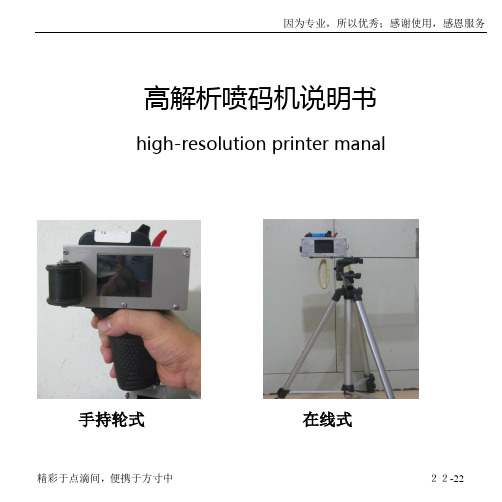
高解析喷码机说明书high-resolution printer manal手持轮式在线式简介国内首家全内置高解析喷码机。
使用水性墨水,可在一系列的多孔和半孔物体表面进行喷印,如纸张/木材/纤维等渗透型材料;使用溶剂性墨水可在其他非渗透型材料表面喷印,如塑料/金属/石材等。
具有一机多用,清晰度高、性能稳定,喷印速度快、使用寿命长,字迹清楚,耗电量小,耗材经济,操作简便等多种优点,体积较小,外置墨盒,全封闭式墨路,快速更换墨盒,更换颜色,节约每一滴墨水。
适用于喷印固定信息和变量信息等生产要求。
感谢信亲爱的用户:感谢您选择我们的产品,能够得到您的信任,我们感到十分荣幸,我们将永远珍惜每为客户的的信任。
我们的产品是国内高解析领域性价比最高的品牌之一。
在你购买,使用中,或者售后时的方方面面,我们会为您竭尽全力,热情细致的服务。
我们会时刻保持提高产品质量,完善细节,以及谦虚谨慎满怀感恩之心的原则做事。
---修己安人目录整机配置清单参数及图解电池使用注意事项常见问题处理保修卡维修记录单安装调试签收单设备配置清单设备参数:1.喷印高度:3--17mm2.喷印速度:0.7米/秒3.喷印精度:最高600dpi4.打印角度:全方位5.喷印内容:各国文字、数字、图形、条码、流水号、当前日期、限制时间等各种符号6.喷印距离:1-8mm可机械调节7.可喷印信息长度:无限制8.可存储信息数量:可见450条9.喷印范围:渗透和非渗透材料10.维护性:溶剂型需要清洗剂,水性不需要11.墨水颜色:黑/红/绿/蓝/黄/白色等12.墨水性质:水性和溶剂型13.工作温度:-10至40度14.充电电源要求:175-250V 50-60Hz开机:按开关机按钮(机器发出两声“滴滴”声音)。
关机:按开关机按钮。
注:1本机采用触摸屏,用手指点击即可。
注:2点击以上图标时,图标15-18mm范围内有效。
一.喷码机开机界面点击进入打印界面点击进入选项调节界面点击进入参数设置界面1.进入-打印界面○1返回上一菜单。


EpsonLW-400VPDATASHEETPresented in a sturdy carry case with a protective rubber casing and two four-metre tapes, this handheld label maker offers great value for money. Specifically designed for warehouses, audio and visual installation services, electricians and othermaintenance industries, this LabelWorks Value Pack (VP) can be used for asset tagging, equipment identification, cable labelling and much more.The LW-400VP is straightforward to use and ideal for busy work environments away from the office. Dedicated buttons give quick access to cutting and printing functions, while an internal memory allows you to save and recall your favourite 50 label designs at any time.The smart, black design helps keep the label maker free from smears and fingerprints, while its black rubber casing provides a protective barrier against scratches and drops. Its black sturdy carry case enables you to transport it easily and safely, and gives you room to take the charging station and up to six tapes with you.The LW-400VP minimises label margins, meaning you get more labels per tape, and Epson’s nine-metre label tape offers economical refills. You don't need to replace tapes quite so often. Two four-metre label tapes are included to get you started – black text on standard white tape, 12mm wide, and black text on strong adhesive yellow tape, 9mm wide.The label maker prints up to four lines and offers excellent versatility thanks to a large number of formats, symbols and font designs. You can see how your labels will look – even in darkness or bright sunlight – thanks to the LW-400VP’s backlit LCD screen.KEY FEATURESErgonomic buttons and keyboard Rubber casingWith tapes, adaptor & carry case 9 barcodes, cable labels For all light conditionsEpson LW-400VPPRODUCT SPECIFICATIONSPRINTINGPrinting technology Thermal transferTape width 6 mm, 9 mm, 12 mm, 18 mmPrinting resolution180 dpiPrintable Dot Numbers64 dot numbersPrint height9 mmPrint speed6 mm/secNumber of printable lines4 LinesMaximum text length80 characters per linePRINT SETTINGSRepeat printing 1 - 9 (Cut mark)Auto increment0-9, a-z, A-ZMirror printing YesVertical printing YesBarcodes Coda bar (NW-7), Code 128, Code 39, EAN-13, EAN-8, ITF, UPC-A, UPC-EWire wrap YesFlag YesFixed Length Auto / 30 mm - 400 mm (1 " - 15 ")Setting Area Whole LabelFONTS & STYLESFonts BR, Bold Gotic, CB, CL Roman, Gothic, Gyosho, Mincho, Reisho, Roman, Sans serif, Sansserif HG, Sans serif ST, Script PL, US RomanFont Size5Frames87 FramesTables2 TablesStyle Bold, Bold & Italic, Bold & Shadow, Italic, Italic & Outline, Italic & Shadow, Normal, Shadow,Shadow & Outline, Shadow & Outline & ItalicAlignment LeftMEMORYMemory alphanumeric62Memory accent185Accent learning YesSymbols459Memory file (saved labels)50Last label YesHARDWARECutter ManualDetection Cover open, Tape widthStrap hole YesKEYBOARDKeyboard type QWERTZNumber of keys61DISPLAYDisplay Resolution128 x 32 dotsDisplay backlight YesNo. of characters per line16Display preview YesNo of lines2Display language Dutch, English, French, German, Italian, Portuguese, Spanish WHAT'S IN THE BOXAC AdaptorMain unitPower cableQuick Memo GuideSupplies CatalogueUser manualWarranty document2 x 4m TapesLOGISTICS INFORMATION SKUC51CB70120Barcode8715946515359 Dimensions Single Carton 315 x 90 x 265 mmCarton Weight2,05 KgUnits5Epson Deutschland GmbHOtto-Hahn-Str. 4D-40670 MeerbuschInfo-Line: 01805/23 41 10 (0,14 /Min. aus dem dt. Festnetz, Epson in ÖsterreichInfo-Line: 0810/20 01 13 (0,07 /Min.) www.epson.atEpson in der Schweiz。
第一章使用条件与注意事项环境温度 0-45℃环境湿度 10-90%RH(非结露)额定电压 220±15%V AC 接地良好额定功率 150W注意事项!墨水及稀释(溶)剂为易燃品,喷码机、墨水和稀释(溶)剂放置应确保附近无明火,并备有干粉灭火器。
!喷码机内有高压,进行检查电路时应切断电源,以防触电!墨水和稀释(溶)剂为刺激性物品,如溅入眼睛或口内,请立即用清水冲洗或及时就诊。
!及时向墨水罐内添加墨水,及时向稀释(溶)剂罐内添加稀释(溶)剂。
!喷码机应可靠接地以保证人身安全!机器使用过程中应水平放置。
机器长期停用时应将墨水全部排出,用清洗剂将墨路进行清洗,方可进行长期停放。
第二章机器结构图2.1喷码机示意图喷头之架:支撑、定位、固定喷头。
喉管:连接主机和喷头的螺旋管,里面包含导线和墨水循环管路。
YX-9100型喷码机有主机和喷头(如图2.1)两大部分组成。
1)主机:主机上舱内部部件如图2.2,主机正面部件如图2.3,主机背面部件见图2.4,主机下舱部件见图2.5,图2.2 主机上舱图风扇:给主机散热。
单片机板:控制喷码机,并对喷码机的各种参数进行自动的调整,使喷码机稳定的工作。
电脑主板:与硬盘、显示屏组成电脑,通过windows系统来调控单片机板。
硬盘:和电脑主板、显示屏组成电脑,存储编辑信息。
触摸屏显示器:和硬盘、显示屏组成电脑,显示操作界面,进行编辑各种喷印信息。
图2.4主机背面图总电源:喷码机供电开关;严禁在电脑未关闭的情况下关闭此开关(断电情况例外)。
USB接口:连接外部信息,可以提取U盘信息并对其内容喷印。
光电接口:连接光电开关。
电脑开关:启动windows系统.同步器接口:连接同步器和编码器。
电源线:喷码机电源连接线。
图2.5主机下舱图主电源:为喷码机输出所需要的电压。
电磁阀:协调墨路的各项功能;稀释剂罐:盛放喷码机专用稀释(溶)剂。
墨水罐:盛放喷码机专用墨水。
小滤:过滤墨水中的杂质。
talento 400Series24-Hour, 7-Day, One and Two Circuit Electronic Time ControlsTECHNICAL DATA Input Voltage:Separate models available for 24V , 120V or 240VAC, 50-60 Hz input Relay Switch Rating:16A @ 24/250 VACOutput Relay:SPDT dry contacts for each channel Power Consumption 5 VA Battery Backup: 3 yearsTemperature Range:–13°F to 131°F (–25°C to 55°C)Display:AM/PM LCD 5/8" x 13/16"Weight: 5.5 oz.Mounting:Surface & DIN rail (NEMA 1 indoor &NEMA 3R outdoor enclosures available)Shortest Switching Time:One secondThe talento 400 controls are one or two chan-nel electronic time switches with 24-hour or 7-day programming.The channels are freely pro-grammable with a total of 30 (model 471) or 40(model 472) schedules.The load status,time of day,and day are displayed on a LCD read-out.In addition to conventional On/Off pro-gramming,the unit provides a “Pulse”and “Cycle”function.Functional DescriptionThe talento 400 time control can be programmed with a 24-hour or 7-day schedule. This control incorporates a calendar through the year 2095and also includes automatic leap year adjust-ment. The annual daylight savings/standard time changes can be programmed to occur automati-cally each year through 2095.TO THE INSTALLER:1. Read operating instructions carefully.2. Check the input voltage ratings marked on the unit to make sure this product is suitable for your power supply and application.3. Disconnect power supply prior to installation to prevent electrical shock.4. Damage to the relay contacts caused by short circuiting will void warranty.5. Wire in accordance with National and Localelectrical code requirements.PAGE 2WIRINGMake certain to connect only to the supply voltage designated on the unit itself. Warranty will be void if wrong voltage is applied. Connect wires to the screw terminals in accordance with the wiring diagram shown (use 12 to 22 AWG wire).INSTALLATION CHECKLIST1. The time switch should have its own independent circuit for power supply.2. Since all electronic instruments are sensitive to volt-age spikes, close attention must be paid to the fol-lowing:a) If possible, power to the electronic time switch should be supplied from a phase different from the one supplying power to the load.b) INDUCTIVE-LOADS should have suitable VARIS-TOR and RC network () across the supply terminals to reduce voltage spikes.c) DC INDUCTIVE LOADS should have a diode across their terminals to eliminate back EMF of the inductor.d) HIGHLY INDUCTIVE LOADS , especially fluores-cent lights, may require a relay in which case (a)and (c) apply.e) IN HIGH LIGHTNING AREAS ,a surge suppres-sor should be installed.InstallationMOUNTINGSurface mounting the talento 400 inside a control panel or enclosure is accomplished with a standard DIN rail.Place the two protruding guides, which are on the top of the rear rail cutout slot, over the top lip of the rail;then snap the bottom into place.For stand-alone installation use a Grasslin indoor/out-door enclosure.PAGE 3KEYPAD DESCRIPTIONDay – Day selector (1 = Mon, 2 = Tue, etc.)Reset*– “Restarts” microprocessor,all programs are preserved+1h – Switch for daylight savings time functions Clear – To cancel program(s)Prog.– Used to review/program/store– Recalls actual time (Time of Day)– S ets the Pulse (momentary contact)command and the Cycle function (“repeating” pulse command)h – Hour advance– Minute advance/select min./sec.– Manual override for each channel & sets command for each channel *Recessed buttons—use a long pen point or pencil LCD DISPLAY ELEMENTSThe LCD incorporates a number of different ele-ments to display various data and information.A new feature of the talento 400 Series is the “Sleep”Mode, an energy saving feature. This feature turns off the LCD (when the unit is not powered) if no but-tons are pressed for a period of two minutes. When in the sleep mode the only character displayed is a flashing Colon ( : ). To restore the full display simply press the clock () button one time.Execution of ProgramsOnce the talento 400 is programmed, it will automatically“look back” and assume the correct ON or OFF switch position.PROGRAM STORAGE CAPACITYThe talento 471 can store up to 30 programs. The talento 472 can store up to 40 programs. To view the number of unused or “free” programs available, press the “Prog.”button until “Fr XX” is displayed. “XX” equals the number of “free” programs remaining.AM/PM displayedDateEnter Pulse/Cycle ResetSelect day(s)of the week Start programinput PROGRAM INSTRUCTIONS TABLE OF CONTENTSSetting Time Format........................................Chart 1 (page 4)Setting Daylight Changeover..........................Chart 2 (page 4)Setting Actual Time.........................................Chart 3 (page 5)Setting 24 Hr./7 Day On/Off Schedule............Chart 4 (page 5)Setting 24 Hr./7 Day Pulse Schedule..............Chart 5 (page 6)Setting 24 Hr./7 Day Cycle Schedule..............Chart 6 (page 6)PAGE 4ProgrammingTIME FORMAT1Full Display AppearsDisplay shows all segments88:88Display shows AM 12:00(00:00 for Military time)“ :”FlashesSelect Start date from chart belowDisplay shows 10.29Select End Date From Chart BelowTo Store and Return to Run ModeDisplay shows 3.26(start date)Complete Steps 1-3 BeforeProgramming TimerNote:Performing the above operation a second time will switch clock to Military time.ENDSTART2002: April 7, October 27PAGE 5ProgrammingACTUAL TIME34Programming 24 Hour / 7 Day“ON/OFF” SCHEDULESENDSTART“—”Moves Under 1-7 with Each PressOnce to Delete,Twice to Restore Day“—”Disappears“—”Appears Under 1 (Mon)PAGE 6Programming 24 Hour / 7 DayPULSEProgramming 24 Hour / 7 DayCYCLEENDEND“—”Appears Under 1 (Mon)“—”Moves Under 1-7 with Each PressOnce to Delete,Twice to Restore Day“—”Disappearsas DescribedAboveShows “– – :– –”PAGE 7MANUAL OVERRIDEEach channel can be manually overridden by pressing the appropriate “Hand switch”. There are two types of manual overrides: “temporary” and “fixed”. A “tempo-rary” override is in effect until the next programmed switch command, at which point the automatic mode takes over. A “fixed” override lasts indefinitely and must be canceled by the user. The LCD displays the operating mode of each channel as follows:=Automatic “ON”=Automatic “OFF”=Temporary “ON”=Temporary “OFF”FIX =Fixed “ON”FIX=Fixed “OFF”PROGRAM REVIEW/EDIT/DELETE With the full display in view:1. Press the “Prog.” button once; the first program is displayed.2. Continue pressing the “Prog.” button to review addi-tional programs, one event at a time.3. To edit a particular command, scroll to its location and change (or add) data as is done during a nor-mal programming procedure – press the “Prog.”button to store the change. When finished, press theclock () button one time to return to the operating mode.4. To delete a particular command, scroll to its location and press the “Clear” button. Continue pressing the“Prog.” button to view additional programs or pressthe clock () button to return to the operatingmode.5. After the last programmed event is viewed, an addi-tional press of the program button will display a free (blank) program location. Additional programs canbe entered at this time.6. After a free (blank) program location is viewed, an additional press of the “Prog.” button will display the free (unused) program locations – displayed as “Fr XX” where “XX” represents the number of unused locations.7. To delete all switching commands; press the “Prog.”button until “Fr XX” is displayed. Press the “Clear”button once, “Cl” is displayed. Press the “Clear” but-ton again. “Cl” flashes and “Fr 30” or “Fr 40” is dis-played. All switching commands are now cleared. Press the clock () button to return to the “Run”mode.BATTERY-POWERED RESERVEIn the event of a power failure, the built-in Lithium bat-tery maintains the current time and date for up to 3years. The program schedule is stored in EEPROM memory and is non-volatile.12345678910111213141516171819202122232425P r i n t e d i n U S A 131U S 06.00TALENTO 400 PROGRAM WORK SHEETDAILY/WEEKLY PROGRAM STEPS。
PSR-4000 MP(UL Name: PSR-4000MP / CA-40MP) LIQUID PHOTOIMAGEABLE SOLDER MASKScreen or Spray ApplicationDark Green, Matte FinishRoHS CompliantExcellent Solder Ball ResistanceHard Surface Finish and Low OdorWide Processing WindowFine Dam ResolutionWithstands ENIG & Immersion TinPSR-4000 MP is a two-component, matte dark Green, alkaline developable LPI solder mask products for flood screen and spray application methods. This product has a low odor, a wide process window and is capable of withstanding alternate metal finishes such as ENIG and immersion Tin. It has a matte Dark Green finish and provides excellent solder ball resistance in no clean flux assembly applications. PSR-4000 MP meets or exceeds the requirements of IPC SM-840E Class H and Class T, Bellcore GR-78-CORE Issue 1, and has a UL flammability rating of 94V-0. All Taiyo America products comply with the Directive 2002/95/EC of the European Parliament and of the Council of 27 January 2003 on the Restriction of the use of certain Hazardous Substances (RoHS) in electrical and electronic equipment.PSR-4000MP C OMPONENTS PSR-4000MP / CA-40MPMixing Ratio 100 parts 25 partsColor Green WhiteMixed PropertiesSolids 80%Viscosity 140-180psSpecific Gravity 1.58M IXING PSR-4000 MP is supplied in pre-measured containers with a mix ratio by weight of 100 parts PSR-4000 MP and 25 parts CA-40MP. PSR-4000 MP can bemixed by hand with a mixing spatula for 10 – 15 minutes. Mixing can be donewith a mechanical mixer at low speeds to minimize shear thinning for 10 – 15minutes. Also, mixing can be done with a paint shaker for 10 – 15 minutes.Pot life after mixing is 72 hours when stored in a dark place at ≤ 25°C (77°F).P RE-C LEANING Prior to solder mask application, the printed circuit board surface needs to be cleaned. Various cleaning methods include Pumice, Aluminum Oxide,Mechanical Brush, and Chemical Clean. All of these methods will provide aclean surface for the application of PSR-4000 MP. Hold time after cleaning theprinted circuit board should be held to a minimum to reduce the oxidation of thecopper surfaces.S CREEN P RINTING Method: Single Sided and Double Sided Screening∙Screen Mesh: 86 – 110∙Screen Mesh Angle: 22.5︒ Bias∙Screen Tension: 20 - 28 Newtons∙Squeegee: 60 – 80 durometer∙Squeegee Angle: 27 – 35︒∙Printing Mode: Flood / Print / Print∙Flood Pressure: 20 – 30 psi∙Printing Speed: 2.0 – 9.9 inches/sec∙Printing Pressure: 60 – 100 psiT ACK D RY C YCLE The Tack Dry step is required to remove solvent from the solder mask film and produce a firm dry surface. The optimum dwell time and oven temperature willdepend on oven type, oven loading, air circulation, exhaust rate, and ramptimes. Excessive tack dry times and temperature will result in difficultydeveloping solder mask from through holes and a reduction in photo speed.Insufficient tack dry will result in artwork marking and/or sticking. Typical tackdry conditions for PSR-4000 MP are as follows:∙Oven Temperature:150 - 185︒F (65 - 85︒C)∙For Single-Sided (Batch Oven)1st Side: Dwell Time: 10 - 20 minutes2nd Side: Dwell Time: 25 - 45 minutes∙For Double-Sided (Conveyorized or Batch Oven)∙Dwell Time: 25 - 60 minutesE XPOSURE PSR-4000 MP requires UV exposure to define solder mask dams and features.The spectral sensitivity of PSR-4000 MP is in the area of 365 nm. Exposuretimes will vary by bulb type and age of the bulb. Below are guidelines forexposing PSR-4000 MP.∙Exposure Unit: 5 kW or higher∙Stouffer Step 21: Clear 10 minimum (on metal / under phototool)∙Energy: 250 mJ / cm2 minimum (under phototool)D EVELOPMENT PSR-4000 MP is developed in an aqueous sodium or potassium carbonatesolution. Developing can be done in either a horizontal or vertical machine.∙Solution: 1% by wt. Sodium Carbonate or 1.2% Potassium Carbonate∙pH: 10.6 or greater∙Temperature: 85 - 105︒F (29 - 41︒C)∙Spray Pressure: 25 - 45 psi∙Dwell Time in developing chamber: 45 - 90 seconds∙Water rinse is needed to remove developer solution followed by a dryingstepF INAL C URE PSR-4000MP requires a thermal cure to insure optimal final property performance.Thermal curing can be done in a batch oven or conveyorized oven.∙Temperature: 275 – 300︒F (135 – 149︒C)∙Time at Temperature: 45 – 60 minutesUV C URE PSR-4000MP has good solder ball resistance. For even better solder ball (O PTIONAL) resistance a UV Bump can be done after Final Cure.∙UV Energy 2000 – 3000 mJ/cm2∙Lamps: High Pressure Mercury Lamps.For Process Optimization please contact your local Taiyo America RepresentativeTaiyo America, Inc. (TAIYO) warrants its products to be free from defects in materials and workmanship for the specified warranty period (PSR-4000 MP / CA-40 MP Warranty period is 12 Months) provided the customer has, at all times, stored the ink at a temperature of 68o F or less. TAIYO accepts no responsibility or liability for damages, whether direct, indirect, or consequential, resulting from failure in the performance of its products. If a TAIYO product is found to be defective in material or workmanship, its liability is limited to the purchase price of the product found to be defective. TAIYO MAKES NO OTHER WARRANTY, EXPRESS OR IMPLIED, AND MAKES NO WARRANTY OF MERCHANTABILITY OR OF FITNESS FOR ANY PARTICULAR PURPOSE. TAIYO'S obligation under this warranty shall not include any transportation charges or costs of installation or any liability for direct, indirect, or consequential damages or delay. If requested by TAIYO, products for which a warranty claim is made are to be returned transportation prepaid to TAIYO'S factory. Any improper use or any alteration of TAIYO'S product by the customer, as in TAIYO'S judgment affects the product materially and adversely,shall void this limited warranty.F INAL P ROPERTIES FOR PSR-4000MP IPC-SM-840E, Class H & T, Solder Mask Vendor Testing RequirementsTESTSM-840PARAGRAPH REQUIREMENT RESULTVisual 3.4.8 Uniform in Appearance Pass Curing 3.4.5 Ref: 3.6.1.1, 3.7.1 and 3.7.2 Pass Non-Nutrient 3.4.6 Does not contribute to biological growth Pass Dimensional 3.4.10 No Solder Pickup and Withstand 500 VDC Pass Pencil Hardness 3.5.1 Minimum “F”Pass – 7H Adhesion 3.5.2 Rigid – Cu, Ni, FR-4 Pass Machinability 3.5.3 No Cracking or Tearing Pass Resistance to Solventsand Cleaning Agents3.6.1.1 Table 3 Solvents PassHydrolytic Stability and Aging 3.6.2No Change after 28 days of 95-99 Cand 90-98% RH PassSolderability 3.7.1 No Adverse Effect J-STD-003 Pass Resistance to Solder 3.7.2 No Solder Sticking Pass Resistance to Solder 3.7.3 No Solder Sticking Pass Simulation of Lead FreeReflow3.7.3.1 No Solder Sticking Pass Dielectric Strength 3.8.1 500 VDC / mil Minimum 2900 VDC/mil Thermal Shock 3.9.3 No Blistering, Crazing or De-lamination Pass Specific Class “H” RequirementsTESTSM-840PARAGRAPH REQUIREMENT RESULTFlammability 3.6.3 UL 94V-0 Pass – File #E166421 Insulation Resistance 3.8.2Before Soldering 5 x 10⁸ ohms minimum Pass (3.7 x 10¹² ohms) After Soldering 5 x 10⁸ ohms minimum Pass (3.1 x 10¹³ ohms) Moisture & Insulation Resistance 3.9.1Before Soldering–In Chamber 5 x 10⁸ ohms minimum Pass (6.4 x 10⁹ ohms) Before Soldering–Out of Chamber 5 x 10⁸ ohms minimum Pass (1.2 x 10¹³ ohms) After Soldering-In Chamber 5 x 10⁸ ohms minimum Pass (1.0 x 10¹⁰ ohms) After Soldering-Out of Chamber 5 x 10⁸ ohms minimum Pass (1.0 x 10¹³ ohms) Electrochemical Migration 3.9.2 >2.0 x 10⁶ ohms, nodendritic growthPass (1.25 x 10¹² ohms)TESTSM-840PARAGRAPH REQUIREMENT RESULTFlammability 3.6.3 Bellcore 02 Index – 28 minimum Pass – 75 Insulation Resistance 3.8.2Before Soldering 5 x 10⁸ ohms minimum Pass (4.3 x 10¹³ ohms) After Soldering 5 x 10⁸ ohms minimum Pass (1.7 x 10¹² ohms)F INAL P ROPERTIES FOR PSR-4000MP Specific Class “T” RequirementsTESTSM-840PARAGRAPH REQUIREMENT RESULTMoisture & Insulation Resistance 3.9.1Before Soldering–In Chamber 5 x 10⁸ ohms minimum Pass (9.9 x 10⁹ ohms) Before Soldering–Out of Chamber 5 x 10⁸ ohms minimum Pass (4.2 x 10¹¹ohms) After Soldering-In Chamber 5 x 10⁸ ohms minimum Pass (1.9 x 10⁹ohms) After Soldering-Out of Chamber 5 x 10⁸ ohms minimum Pass (2.2 x 10¹¹ohms)Electrochemical Migration 3.9.2 < 1 decade drop, no dendriticgrowthPassAdditional Tests / ResultsTEST REQUIREMENT RESULT Dielectric Constant Internal Test at 1 MHz 4.7 Dissipation Factor Internal Test at 1 MHz 0.0220Outgassing Test ASTM E-595-90A 2 J/cm2 UV Cure was done after thermal cureTML ≤ 1 %CVCM ≤ 0.10%TML-0.62%CVCM-0.01%Electroless Nickel / Immersion Gold Resistance Nickel (85C/30 min) Tape Test Adhesion Pass Solvent Resistance Acetone: No attack – 24 hours PassMEK: No attack – 24 hours PassIPA: No attack – 24 hours PassPMA: No attack – 24 hours Pass Acid Resistance HCI – 10%: No attack – 30 Minutes PassH2SO4– 10%: No attack – 30 Minutes Pass Base Resistance NaOH – 10%: No attack – 30 Minutes PassBoiling Water Resistance: No attack – 15 Minutes Pass Solder / Flux Resistance (Alphametals)Alpha 857 water soluble: No attack – 1 x 10 sec float (260C) PassNR060 no-clean: No attack – 1 x 10 sec float (260C) Pass3355-NB rosin-based: No attack – 1 x 10 sec float (260C) PassNR-3000A4 no-clean: No attack – 1 x 10 sec float (260C) Pass Solder / Flux Resistance (Multicore)X32-10M no-clean: No attack – 1 x 10 sec float (260C) PassX32-06I no-clean: No attack – 1 x 10 sec float (260C) Pass Solder/Flux Resistance-(Sanwa) SR-270 rosin-based: No attack – 1 x 10 sec float (260C) Pass Conformal Coating Adhesion: Humiseal 1 B31 acrylic: Crosscut (10/10) after tape 100/100Humiseal 1A20 urethane: Crosscut (10/10) after tape 100/100 Dow Corning 3-1753 silicone: Crosscut (10/10) after tape 100/100 Glue Dot Adhesion – Loctite 3609 Adhesion of Glue Dot to PSR-4000MP Excellent。
R400OperatorManualContentsContents.........................................................................................................................2Chapter1.ProductOverview.........................................................................................11.1Mainparts........................................................................................................11.2ControlPanel................................................................................................21.3PrintHead.........................................................................................................31.4InkCompartment.............................................................................................41.5MainScreen......................................................................................................51.6MenuDescription.............................................................................................51.6.1Messagemenu......................................................................................51.6.2Editor.....................................................................................................61.6.3UserFields.............................................................................................71.6.4Password...............................................................................................71.6.5System...................................................................................................81.6.6Configure...............................................................................................91.6.7Data.....................................................................................................101.7Specifications.................................................................................................1117.1ElectricalSpecification.........................................................................111.7.2Weight.................................................................................................111.7.3Dimensions..........................................................................................111.7.4EnvironmentalSpecifications..............................................................12Chapter2.PrinterOperation.......................................................................................132.1.Introduction..................................................................................................132.2.Installationmethodusedforthefirsttime...................................................132.2.1ManualInkInjection............................................................................132.2.2ExhausttheairofPipeSystem............................................................142.3StartPrint.......................................................................................................162.3.1StartJet...............................................................................................162.3.2InklineObservation............................................................................172.3.3SplitPointObservation.......................................................................182.4TurnoffthePrinter.........................................................................................192.4.1CleanStopNormally.........................................................................192.4.2Cleanstop(Powerfailureduringtheusage).......................................192.4.3Cleanstop(longtermshutdown).......................................................192.5ManageMessage...........................................................................................202.5.1CreateaMessage................................................................................202.6ManageUserField..........................................................................................212.6.1Time.....................................................................................................212.6.2Two-dimensionalCodeandBarcode..................................................222.6.3Counter................................................................................................232.6.4Logo.....................................................................................................242.6.5Multipleuserfieldstogenerateonebarcode.....................................252.7MessageParameters......................................................................................262.8PrintConfiguration.........................................................................................282.8.1Limitedprinttimesconfiguration.......................................................282.8.2ContinuousPrint..................................................................................302.8.3MeterMode........................................................................................332.8.4ReverseMode.....................................................................................34Chapter3.TroubleShootingandMaintenance..........................................................383.1Diagnosticscreen...........................................................................................383.2FaultandWarningIcon..................................................................................40