微型开关
- 格式:pdf
- 大小:253.10 KB
- 文档页数:2
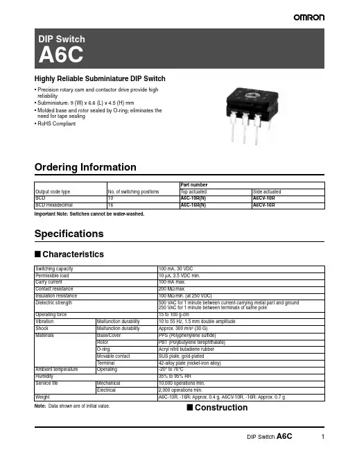
Highly Reliable Subminiature DIP Switch•Precision rotary cam and contactor drive provide high reliability•Subminiature: 9 (W) x 6.6 (L) x 4.5 (H) mm•Molded base and rotor sealed by O-ring; eliminates the need for tape sealing •RoHS CompliantOrdering InformationImportant Note: Switches cannot be water-washed.Specifications■CharacteristicsNote: Data shown are of initial value.■ConstructionOutput code type No. of switching positions Part numberTop actuated Side actuated BCD10A6C-10R(N)A6CV-10R BCD Hexadecimal16A6C-16R(N)A6CV-16RSwitching capacity 100 mA, 30 VDC Permissible load 10 µA, 3.5 VDC min.Carry current 100 mA max.Contact resistance 200 M Ω max.Insulation resistance 100 M Ω min. (at 250 VDC)Dielectric strength 500 VAC for 1 minute between current-carrying metal part and ground 250 VAC for 1 minute between terminals of same pole Operating force 15 to 100 g-cmVibration Malfunction durability 10 to 55 Hz, 1.5 mm double amplitude Shock Malfunction durability Approx. 300 m/s 2 (30 G)MaterialsBase/Cover PPS (Polyphenylene sulfide)Rotor PBT (Polybutylene terephthalate)O-ringAcryl nitril butadiene rubber Movable contact SUS plate, gold-plated T erminal42-alloy plate (nickel-iron alloy)Ambient temperature Operating-20° to 70°C Humidity 35% to 95% RH Service life Mechanical 10,000 operations min.Electrical 2,000 operations min.WeightA6C-10R, -16R: Approx. 0.4 g, A6CV-10R, -16R: Approx. 0.7 gThe movable contactor is moved as the rotor rotates. The terminalsare insert molded into the base. The rotor is secured by an O-ring and the case and the cover are made of plastic resin. Therefore, the internal mechanism is effectively sealed.DimensionsUnit: mm (inch)■A6C-10R(N)■A6CV-10R■A6C-16R(N)■A6CV-16RTerminal arrangement (bottom view)Mounting holesPCB dimension(Top view)Internal connections(top view)Omron Electronic Components, LLCTerms and Conditions of Sales1.Definitions: The words used herein are defined as follows.(a) Terms:These terms and conditions(b) Seller:Omron Electronic Components LLC and its subsidiaries(c) Buyer:The buyer of Products, including any end user in section III through VI(d) Products:Products and/or services of Seller(e) Including:Including without limitation2.Offer; Acceptance: These Terms are deemed part of all quotations, acknowledgments,invoices, purchase orders and other documents, whether electronic or in writing, relating to the sale of Products by Seller. Seller hereby objects to any Terms proposed in Buyer's purchase order or other documents which are inconsistent with, or in addition to, these Terms.3.Distributor: Any distributor shall inform its customer of the contents after and includingsection III of these Terms.1.Prices; Payment: All prices stated are current, subject to change without notice by Seller.Buyer agrees to pay the price in effect at time of shipment. Payments for Products received are due net 30 days unless otherwise stated in the invoice. Buyer shall have no right to set off any amounts against the amount owing in respect of this invoice.2.Discounts: Cash discounts, if any, will apply only on the net amount of invoices sent toBuyer after deducting transportation charges, taxes and duties, and will be allowed only if (a) the invoice is paid according to Seller's payment terms and (b) Buyer has no past due amounts owing to Seller.3.Interest: Seller, at its option, may charge Buyer 1.5% interest per month or the maximumlegal rate, whichever is less, on any balance not paid within the stated terms.4.Orders: Seller will accept no order less than 200 U.S. dollars net billing.5.Currencies: If the prices quoted herein are in a currency other than U.S. dollars, Buyershall make remittance to Seller at the then current exchange rate most favorable to Seller; provided that if remittance is not made when due, Buyer will convert the amount to U.S. dollars at the then current exchange rate most favorable to Seller availableduring the period between the due date and the date remittance is actually made.ernmental Approvals: Buyer shall be responsible for all costs involved in obtainingany government approvals regarding the importation or sale of the Products.7.Taxes: All taxes, duties and other governmental charges (other than general real propertyand income taxes), including any interest or penalties thereon, imposed directly orindirectly on Seller or required to be collected directly or indirectly by Seller for themanufacture, production, sale, delivery, importation, consumption or use of the Products sold hereunder (including customs duties and sales, excise, use, turnover and license taxes) shall be charged to and remitted by Buyer to Seller.8.Financial: If the financial position of Buyer at any time becomes unsatisfactory to Seller,Seller reserves the right to stop shipments or require satisfactory security or payment in advance. If Buyer fails to make payment or otherwise comply with these Terms or any related agreement, Seller may (without liability and in addition to other remedies) cancel any unshipped portion of Products sold hereunder and stop any Products in transit until Buyer pays all amounts, including amounts payable hereunder, whether or not then due, which are owing to it by Buyer. Buyer shall in any event remain liable for all unpaid accounts.9.Cancellation; Etc: Orders are not subject to rescheduling or cancellation unless Buyerindemnifies Seller fully against all costs or expenses arising in connection therewith. 10.Force Majeure: Seller shall not be liable for any delay or failure in delivery resulting fromcauses beyond its control, including earthquakes, fires, floods, strikes or other labor disputes, shortage of labor or materials, accidents to machinery, acts of sabotage, riots, delay in or lack of transportation or the requirements of any government authority.11.Shipping; Delivery: Unless otherwise expressly agreed in writing by Seller:(a) All sales and shipments of Products shall be FOB shipping point (unless otherwisestated in writing by Seller), at which point title to and all risk of loss of the Products shall pass from Seller to Buyer, provided that Seller shall retain a security interest in theProducts until the full purchase price is paid by Buyer;(b) Delivery and shipping dates are estimates only; and(c) Seller will package Products as it deems proper for protection against normalhandling and extra charges apply to special conditions.12.Claims: Any claim by Buyer against Seller for shortage or damage to the Productsoccurring before delivery to the carrier must be presented in detail in writing to Seller within 30 days of receipt of shipment.1.Suitability: IT IS THE BUYER’S SOLE RESPOINSIBILITY TO ENSURE THAT ANYOMRON PRODUCT IS FIT AND SUFFICIENT FOR USE IN A MOTORIZED VEHICLE APPLICATION. BUYER SHALL BE SOLELY RESPONSIBLE FOR DETERMINING APPROPRIATENESS OF THE PARTICULAR PRODUCT WITH RESPECT TO THE BUYER’S APPLICATION INCLUDING (A) ELECTRICAL OR ELECTRONICCOMPONENTS, (B) CIRCUITS, (C) SYSTEM ASSEMBLIES, (D) END PRODUCT, (E) SYSTEM, (F) MATERIALS OR SUBSTANCES OR (G) OPERATING ENVIRONMENT.Buyer acknowledges that it alone has determined that the Products will meet theirrequirements of the intended use in all cases. Buyer must know and observe allprohibitions of use applicable to the Product/s.e with Attention: The followings are some examples of applications for whichparticular attention must be given. This is not intended to be an exhaustive list of all possible use of any Product, nor to imply that any use listed may be suitable for any Product:(a) Outdoor use, use involving potential chemical contamination or electricalinterference.(b) Use in consumer Products or any use in significant quantities.(c) Energy control systems, combustion systems, railroad systems, aviation systems,medical equipment, amusement machines, vehicles, safety equipment, andinstallations subject to separate industry or government regulations.(d) Systems, machines, and equipment that could present a risk to life or property.3.Prohibited Use: NEVER USE THE PRODUCT FOR AN APPLICATION INVOLVINGSERIOUS RISK TO LIFE OR PROPERTY WITHOUT ENSURING THAT THE SYSTEM AS A WHOLE HAS BEEN DESIGNED TO ADDRESS THE RISKS, AND THAT THE PRODUCT IS PROPERLY RATED AND INSTALLED FOR THE INTENDED USEWITHIN THE OVERALL EQUIPMENT OR SYSTEM.4.Motorized Vehicle Application: USE OF ANY PRODUCT/S FOR A MOTORIZEDVEHICLE APPLICATION MUST BE EXPRESSLY STATED IN THE SPECIFICATION BY SELLER.5.Programmable Products: Seller shall not be responsible for the Buyer's programming ofa programmable Product.1.Warranty: Seller's exclusive warranty is that the Products will be free from defects inmaterials and workmanship for a period of twelve months from the date of sale by Seller (or such other period expressed in writing by Seller). SELLER MAKES NO WARRANTY OR REPRESENTATION, EXPRESS OR IMPLIED, ABOUT ALL OTHER WARRANTIES, NON-INFRINGEMENT, MERCHANTABILITY OR FITNESS FOR A PARTICULARPURPOSE OF THE PRODUCTS.2.Buyer Remedy: Seller's sole obligation hereunder shall be to replace (in the formoriginally shipped with Buyer responsible for labor charges for removal or replacement thereof) the non-complying Product or, at Seller's election, to repay or credit Buyer an amount equal to the purchase price of the Product; provided that there shall be noliability for Seller or its affiliates unless Seller's analysis confirms that the Products were handled, stored, installed and maintained and not subject to contamination, abuse,misuse or inappropriate modification. Return of any Products by Buyer must beapproved in writing by Seller before shipment.3.Limitation on Liability: SELLER AND ITS AFFILIATES SHALL NOT BE LIABLE FORSPECIAL, INDIRECT, INCIDENTAL OR CONSEQUENTIAL DAMAGES, LOSS OF PROFITS OR PRODUCTION OR COMMERCIAL LOSS IN ANY WAY CONNECTED WITH THE PRODUCTS, WHETHER SUCH CLAIM IS BASED IN CONTRACT,WARRANTY, NEGLIGENCE OR STRICT LIABILITY. FURTHER, IN NO EVENT SHALL LIABILITY OF SELLER OR ITS AFFILITATES EXCEED THE INDIVIDUAL PRICE OF THE PRODUCT ON WHICH LIABILITY IS ASSERTED.4.Indemnities: Buyer shall indemnify and hold harmless Seller, its affiliates and itsemployees from and against all liabilities, losses, claims, costs and expenses (including attorney's fees and expenses) related to any claim, investigation, litigation or proceeding (whether or not Seller is a party) which arises or is alleged to arise from Buyer's acts or omissions under these Terms or in any way with respect to the Products.1.Intellectual Property: The intellectual property embodied in the Products is the exclusiveproperty of Seller and its affiliates and Buyer shall not attempt to duplicate it in any way without the written permission of Seller. Buyer (at its own expense) shall indemnify and hold harmless Seller and defend or settle any action brought against Seller to the extent that it is based on a claim that any Product made to Buyer specifications infringedintellectual property rights of another party.2.Property; Confidentiality: Notwithstanding any charges to Buyer for engineering ortooling, all engineering and tooling shall remain the exclusive property of Seller. All information and materials supplied by Seller to Buyer relating to the Products areconfidential and proprietary, and Buyer shall limit distribution thereof to its trustedemployees and strictly prevent disclosure to any third party.3.Performance Data: Performance data is provided as a guide in determining suitabilityand does not constitute a warranty. It may represent the result of Seller's test conditions, and the users must correlate it to actual application requirements.4.Change In Specifications: Product specifications and description may be changed at anytime based on improvements or other reasons. It is Seller’s practice to change part numbers when published ratings or features are changed, or when significantengineering changes are made. However, some specifications of the Product may be changed without any notice.5.Errors And Omissions: The information on Seller’s website or in other documentationhas been carefully checked and is believed to be accurate; however, no responsibility is assumed for clerical, typographical or proofreading errors or omissions.6.Export Controls: Buyer shall comply with all applicable laws, regulations and licensesregarding (a) export of the Products or information provided by Seller; (b) sale ofProducts to forbidden or other proscribed persons or organizations; (c)disclosure to non-citizens of regulated technology or information.1.Waiver: No failure or delay by Seller in exercising any right and no course of dealingbetween Buyer and Seller shall operate as a waiver of rights by Seller.2.Assignment: Buyer may not assign its rights hereunder without Seller's written consent.w: These Terms are governed by Illinois law (without regard to conflict of laws). Federaland state courts in Illinois have exclusive jurisdiction for any dispute hereunder.4.Amendment: These Terms constitute the entire agreement between Buyer and Sellerrelating to the Products, and no provision may be changed or waived unless in writing signed by the parties.5.Severability: If any provision hereof is rendered ineffective or invalid, such provision shallnot invalidate any other provision.Certain Precautions on Specifications and UseOMRON ON-LINEGlobal - USA - Cat. No. J01C-E-01Printed in USAOMRON ELECTRONIC COMPONENTS LLC55 E. Commerce Drive, Suite B Schaumburg, IL 60173847-882-228801/07 Specifications subject to change without noticeComplete “Terms and Conditions of Sale” for product purchase and use are on Omron’s website at – under the “About Us” tab, in the Legal Matters section.ALL DIMENSIONS SHOWN ARE IN MILLIMETERS.T o convert millimeters into inches, multiply by 0.03937. To convert grams into ounces, multiply by 0.03527.。
GLDB01C GLCB-01A4J GLCB01E7B GLCA01C GLCB-01A1B GLCB-01A2B GLDB01C GLCA05A1A GLCB01D GLEA01A4JMICRO SWITCH™ GLS Global Miniature (EN50047) Limit Switches Datasheet2What makes our switches better?Meets EN50047 mounting standards and EN/IEC electricalstandards for world-wide use Large existing install base and channel allows for quick deliveryworldwide Wide range of actuators and circuitry options in same footprint Certified for global use with CCC, CSA, CE, and UL acceptanceMICRO SWITCH™ GLS Miniature (EN50047 Style) Limit SwitchesThe Honeywell MICRO SWITCH™ GLS miniature limit switch family offers a wide range of products for global solutions. These durable and reliable limit switches are suitable for many industrial applications, agriculture equipment, transportation equipment, and other applications requiring an environmentally sealed (IP and NEMA) switch.The compact housings are often ideal for equipment where space is at a premium. The extensive product range is available in three different housing types; metal housing, plastic housing or a three conduit metal housing which are mounting compatible to EN50047. A wide range of actuators, contact blocks, and conduit/connectivity options enhance the product offering.In today’s demanding age of logic-level controls, electromechanical switches are frequently used to interface with PLCs and other logic level devices. GLS limit switches offer an option for gold-plated contacts for the standard switch. This option promotes the switch reliability for logic-level applications.EASY TO INSTALL AND MAINTAIN • GLOBAL RUGGED CONSTRUCTION • BUILT TO FITMiniature global limit switchwith heavy-duty ratings.Features and Benefits HOUSING MATERIAL OPTIONSMICRO SWITCH™ GLS limit switches are manufactured with either a metal housing or double-insulated plastic housing for indoor and outdoor applications.FLEXIBLE OPERATING HEADSFull range of actuator heads can be positioned at 90° increments for design flexibility. Side rotary actuator heads can be factory set for CW, CCW, or CW and CCW actuation to meet application requirements.BUILT FOR LONG LIFEDual bearing design on side rotary actuators reduces side loading and enhances mechanical life.CIRCUITRY OPTIONSWide variety of normally closed and normally open double-break snap-actionor slow-action contact options are available with silver contacts for power switching or gold-plated contacts for low energy loads.CIRCUIT FLEXIBILITYNormally closed double break direct opening contactsconform toEN/IEC 60947-5-1-3 to provide forced opening of the normally closed contact. Each contact throw is electrically isolated to accept different voltages (Form Zb contacts) which provides circuit flexibility. Double pole double throw (2NC/2NO) contact option require same polarity for each pole. (Form Za for each pole).LOW TEMPERATURE FOR SEVERE ENVIRONMENTS-40 °C [-40 °F] standard construction for side rotary and plunger actuated switches are suitable for many severe outdoor environments.GLOBAL ACCEPTANCEWith sealing up to IP66 and NEMA 4 for hostile environments, MICRO SWITCH™ GLS Series switches also carry CE, UL, CSA, CCC certification forglobal use.Galvanically isolated contacts for controllingtwo separate circuits.Removable contact block for wiring ease.34PASSENGER ELEVATORSBuffer actuation, top stop, floor detectionCOMMERICAL APPLIANCESDoor interlock switchESCALATORS/MOVING STAIRSSide skirt detection, loose or missing tread, comb detectionSCISSOR/PLATFORM LIFTSPothole detection, outrigger position, boom extend/retractMATERIAL HANDLINGOverhead doorsMACHINE TOOL EQUIPMENTPart presence, machine slide/table position, panel and door presenceOFF-ROAD EQUIPMENT• Agriculture planting and tillage equipment, stow position• Road construction equipment, panel & door interlock switches • Rail passenger door interlock switch •Position of motorized railroad switchPotential Applications5MICRO SWITCH™ GLS Global Miniature (EN50047 Style) Limit SwitchesMICRO SWITCH™ GLS SERIES PRODUCT NOMENCLATUREGLSwitch TypeA1AHead/ActuatorBodyCNOTE: not all combinations of model codes are available.Please contact your Honeywell provider/representative for assistance.ConduitAGLS Series Global Limit SwitchL01Basic SwitchModification CodesFor Actuator types beginning with A**For Type A modification codes,more than one code may be permissible. For example,GLCA01A1B-13 is a side rotary,lever-actuated switch,GLCA01A1B, adjusted for clock-wise actuation only. The operating shaft is to the right side of the switch when viewing the switch from the front (label side).6GLS SeriesTable 2. Electrical RatingsIEC 60947-5-1 (EN60947-5-1) AC 15, A300; DC 13, Q3007MICRO SWITCH™ GLS Global Miniature (EN50047 Style) Limit SwitchesMICRO SWITCH™ GLC SERIES ORDER GUIDE/RECOMMENDED LISTINGSFor listings not shown, contact your Honeywell representative.1Contact closed n ; Contact open o . *Positive opening occurs.1Contact closed n ; Contact open o . *Positive opening occurs.Table 5. Side Rotary Adjustable, Plastic Roller1Contact closed n ; Contact open o . *Positive opening occurs.8GLS Series1Contact closed n ; Contact open o . *Positive opening occurs.Table 7. Side Rotary Adjustable, Metal Rod, A4J (140 mm rod) and A4L (200 mm rod)1Contact closed n ; Contact open o . *Positive opening occurs.1Contact closed n ; Contact open o . *Positive opening occurs.MICRO SWITCH™ GLC SERIES ORDER GUIDE/RECOMMENDED LISTINGSFor listings not shown, contact your Honeywell representative.MICRO SWITCH™ GLS Global Miniature (EN50047 Style) Limit SwitchesMICRO SWITCH™ GLC SERIES ORDER GUIDE/RECOMMENDED LISTINGSFor listings not shown, contact your Honeywell representative.1Contact closed n ; Contact open o . *Positive opening occurs.Table 10. Top Pin Plunger110Table 12. Top Roller LeverMICRO SWITCH™ GLC SERIES ORDER GUIDE/RECOMMENDED LISTINGSFor listings not shown, contact your Honeywell representative.Figure 1. GLC Side Rotary • A1, A1A, A1B, and A1YFigure 2. GLC Side Rotary • A2, A2A, A2B, and A2YFigure 5. GLC Side Rotary • A9A1Contact closed n; Contact open o.117,2 mm [0.28 in]for 0.5-14 NPTconduit threads.7,2 mm [0.28 in] for 0.5-14 NPT conduit threads.7,2 mm [0.28 in] for0.5-14 NPT conduitthreads.Figure 10. GLC Wobble • K8A/K8B7,2 mm [0.28 in] for0.5-14 NPT conduitthreads.Figure 11. GLC ConduitFor listings not shown, contact your Honeywell representative.1Contact closed n; Contact open o. *Positive opening occurs.1Contact closed n; Contact open o. *Positive opening occurs.13For listings not shown, contact your Honeywell representative. Table 18. Side Rotary Adjustable, Plastic Roller1Contact closed n; Contact open o. *Positive opening occurs. **No roller1Contact closed n; Contact open o. *Positive opening occurs.For listings not shown, contact your Honeywell representative.1Contact closed n; Contact open o. *Positive opening occurs.1Contact closed n; Contact open o. *Positive opening occurs.1Contact closed n; Contact open o. *Positive opening occurs.1516Table 23. Side Rotary, 50 mm Rubber Roller1Contact closed n ; Contact open o . *Positive opening occurs.1Contact closed n ; Contact open o . *Positive opening occurs.MICRO SWITCH™ GLD SERIES ORDER GUIDE/RECOMMENDED LISTINGSFor listings not shown, contact your Honeywell representative.17MICRO SWITCH™ GLD SERIES ORDER GUIDE/RECOMMENDED LISTINGSFor listings not shown, contact your Honeywell representative.181Contact closed n ; Contact open o .MICRO SWITCH™ GLD SERIES ORDER GUIDE/RECOMMENDED LISTINGSFor listings not shown, contact your Honeywell representative.19Figure 13. GLD Side Rotary • A2, A2A, A2B, and A2YFigure 14. GLD Side Rotary Rod • A4J (140 mm) & A4L (200 mm)0.5-14 NPT conduitthreads.0.5-14 NPT conduitthreads.7,2 mm [0.28 in] for 0.5-14 NPT conduitthreads.MICRO SWITCH™ GLD DIMENSIONAL DRAWINGS mm [in]7,2 mm [0.28 in] for0.5-14 NPT conduit threads.Figure 21. GLD Wobble • K8A/K8BMICRO SWITCH™ GLD DIMENSIONAL DRAWINGS mm [in]1Contact closed n ; Contact open o . *Positive opening occurs. † 0.5-14 NPT conduit option includes adapter.Table 31. Side Rotary, Metal Roller1Contact closed n ; Contact open o . *Positive opening occurs. † 0.5-14 NPT conduit option includes adapter.MICRO SWITCH™ GLE SERIES ORDER GUIDE/RECOMMENDED LISTINGSFor listings not shown, contact your Honeywell representative.1Contact closed n ; Contact open o . *Positive opening occurs. † 0.5-14 NPT conduit option includes adapter.Table 33. Side Rotary Adjustable, Metal Roller1Contact closed n ; Contact open o . *Positive opening occurs.† 0.5-14 NPT conduit option includes adapter.MICRO SWITCH™ GLE SERIES ORDER GUIDE/RECOMMENDED LISTINGSFor listings not shown, contact your Honeywell representative.1Contact closed n ; Contact open o . *Positive opening occurs. † 0.5-14 NPT conduit option includes adapter.1Contact closed n ; Contact open o . *Positive opening occurs. † 0.5-14 NPT conduit option includes adapter.Table 37. Side Rotary Conveyor Lever, Ceramic Roller1Contact closed n ; Contact open o . *Positive opening occurs.MICRO SWITCH™ GLE SERIES ORDER GUIDE/RECOMMENDED LISTINGSFor listings not shown, contact your Honeywell representative.MICRO SWITCH™ GLE SERIES ORDER GUIDE/RECOMMENDED LISTINGS For listings not shown, contact your Honeywell representative.11Contact closed n ; Contact open o .MICRO SWITCH™ GLE SERIES ORDER GUIDE/RECOMMENDED LISTINGSFor listings not shown, contact your Honeywell representative.Figure 24. GLE Side Rotary • A2, A2A, A2B, and A2YFigure 25. GLE Side Rotary • A4J and A4LMICRO SWITCH™ GLE DIMENSIONAL DRAWINGS mm [in]Figure 31. GLE Wobble • E7BFigure 33. GLE Conduit Adapter for 0.5-14 NPT MICRO SWITCH™ GLE DIMENSIONAL DRAWINGS mm [in]REPLACEMENT PARTS - BASIC SWITCHESFACTORY PRE-WIRED LIMIT SWITCHES WITH INTEGRAL CONNECTORFACTORY PRE-WIRED LIMIT SWITCHES WITH INTEGRAL CONNECTOREpoxy coated metal Limit SwitchesGLCC01B-D1: Top pin plunger, 1NC/1NO snap action, with Deutsch DT style 4 pin connector GLCC01C-D1: Top roller plunger, 1NC/1NO snap action, with Deutsch DT style 4 pin connector GLCC06A1B-D1: Side rotary with metal roller, 2NC slow action, with Deutsch DT style 4 pin con-nectorPlastic Limit SwitchesGLDC01A1A-D1: Side rotary with plastic roller, 1NC/1NO snap action, with Deutsch DT style 4 pin connectorGLDC01A1B-D1: Side rotary with metal roller, 1NC/1NO snap ac-tion, with Deutsch DT style 4 pin connectorGLDC01C-D1: Top roller plunger, 1NC/1NO snap action, with Deutsch DT style 4 pin connectorNote: Reference base catalog listing for switch characteristics. For example, cat. listing GLCC01B-D1 has base cat. listing GLCC01B.Connector Without Limit SwitchGLZ8C-DEU : DT style 4 pin connector prewired with 6 in. of lead wires (4) and 20mm conduit thread with jam nutGLZ8C-PA : DT style 4 pin connector packet with all parts furnished unassembled for a 20 mm conduit threadGLCA01A1A GLCA01A1B GLCA01A1B-3GLCA01A2A GLCA01A2B GLCA01A4J GLCA01A5B GLCA01A9A GLCA01B GLCA01C GLCA01C-6GLCA01D GLCA01E7B GLCA01K8A GLCA01K8B GLCA03A1A GLCA03A1B GLCA03B GLCA03C GLCA03C-6GLCA03D GLCA03E7B GLCA03K8B GLCA04A1B GLCA04A2B GLCA04B GLCA05A1A GLCA06A1B-4GLCA06A5B GLCA06C-6GLCA06E7B GLCA07A1B-3GLCA36A5B GLCA36D GLCB01A1A GLCB01A1A/4GLCB01A1B GLCB01A2A GLCB01A2B GLCB01A4J GLCB01A4L GLCB01A5B GLCB01A9AThis datasheet supports the following MICRO SWITCH™ GLS Series Limit SwitchesGLCB01B GLCB01C GLCB01D GLCB01E7B GLCB01K8A GLCB01K8B GLCB03A1B GLCB03A2A GLCB03B GLCB03C GLCB03D GLCB04A1B GLCB04B GLCB04C GLCB04D GLCB06A1B GLCB06A1B-3GLCB06A1B-4GLCB06A2B GLCB06B GLCB06C GLCB07A1B GLCB07A1B-3GLCB07A2B GLCB07B GLCB07C GLCB07D GLCB07E7B GLCB33DGLCB34A1B-5GLCB35A1B-5GLCB36C GLCC01A1A GLCC01A1B GLCC01A2B GLCC01A4J GLCC01A9A GLCC01B GLCC01B-D1GLCC01C GLCC01C-D1GLCC01D GLCC01E7BGLCC03A2B GLCC06A1B-D1GLCC06C GLCC06D GLCC07A1A GLCC07A1B GLCC07A2B GLCD03A1A GLCD03B GLDA01A1A GLDA01A1A-D GLDA01A1B GLDA01A1B-D GLDA01A1Y GLDA01A2A GLDA01A2B GLDA01A2Y GLDA01A4J GLDA01A5B GLDA01A9A GLDA01B GLDA01C GLDA01C-D GLDA01D GLDA01E7B GLDA01K8B GLDA03A1A GLDA03A1B GLDA03A1Y GLDA03A2Y GLDA03A9A GLDA03B GLDA03C GLDA03C-6GLDA03D GLDA03E7B GLDA03K8B GLDA04A2B GLDA04A4J GLDA04B GLDA05A2B GLDA06A1B GLDA06A2AGLDA06A9A GLDA06C GLDA06D GLDA07A2B GLDA07A9A GLDA07C GLDB01A1-3GLDB01A1A GLDB01A1B GLDB01A1B3GLDB01A1Y GLDB01A2GLDB01A2A GLDB01A2B GLDB01A2Y GLDB01A4J GLDB01A5B GLDB01B GLDB01C GLDB01D GLDB01D-D GLDB01E7B GLDB01K8B GLDB03A1A GLDB03A1B GLDB03A1Y GLDB03A1Y-3GLDB03A1Y-4GLDB03A2A GLDB03A2Y GLDB03B GLDB03C GLDB03C-6GLDB03D GLDB04A1A GLDB04B GLDB04C GLDB04D GLDB06A1B GLDB06A2A GLDB06C GLDB07A1A GLDB07A1BGLDB07A2A GLDB07A2B GLDB07B GLDB07C GLDB33C GLDB33C-6GLDB36A5B GLDB36C GLDB36C-6GLDC01A1A GLDC01A1A-D1GLDC01A1B GLDC01A1B-D1GLDC01A1Y GLDC01A2A GLDC01A2B GLDC01A4J GLDC01A5B GLDC01A9A GLDC01B GLDC01C GLDC01C-D1GLDC01D GLDC01E7B GLDC01K8B GLDC03A4J GLDC03C GLDC03D GLDC04B GLDC05A1A GLDC05A2A GLDC05B GLDC05C GLDC05D GLDC06A1A GLDC06A1B GLDC06C GLDC06D GLDC07A1B GLDC07B GLDD01A1B GLDD01D GLEA01A1AGLEA01A1B GLEA01A2A GLEA01A2B GLEA01A4J GLEA01A5A GLEA01A5B GLEA01B GLEA01C GLEA01D GLEA01E7B GLEA06D GLEA24A1B GLEA24A1B-C GLEA24A2A GLEA24A2B GLEA24A4J GLEA24A5B GLEA24B GLEA24C GLEA24C-6GLEA24D GLEA24E7B GLEA32A1A GLEB01A1A GLEB01A1B GLEB01A2A GLEB01A2B GLEB01A4J GLEB01A5A GLEB01A5B GLEB01A9A GLEB01B GLEB01C GLEB01D GLEB01E7B GLEB01K8A GLEB03A5B GLEB03B GLEB04A1B GLEB06A1A GLEB07A1B GLEB07A2B GLEB07BGLEB07C GLEB07K8A GLEB24A1B GLEB24A2B GLEB24B GLEB24C GLEB24C-6GLEB24D GLEB24E7B GLEB24K8A GLEB32A1A GLEB33B GLEC01A1B GLEC01A2B GLEC01A4J GLEC01A9A GLEC01B GLEC01C GLEC01D GLEC03B GLEC24A1B GLEC24A2A GLEC24B GLEC24C GLEC24D GLEC32B GLEC33B GLED01D GLZ301GLZ303GLZ304GLZ306GLZ307GLZ332GLZ333GLZ334GLZ336GLZ8C-DEU GLZ8C-PAGLS SeriesADDITIONAL INFORMATIONThe following associated literature is available on the Honeywell web site at :• Product installation instructions• Aerospace range guide• Transportation range guide• Limits and Machine Safety range guide• Product application-specific information– Application Note: Sensors and Switches for Industrial ManualProcess Valves– Application Note: Sensors and Switches Used in ValveActuators and Valve Positioners– Industrial Machinery Switch Guide– Limit and Enclosed Switches Application Information– Limit and Enclosed Switches Operating Characteristics – Limit and Enclosed Switches Reference Standards– Limit and Enclosed Switches Typical Applications– Sensors and Switches in Mobile Cranes– Sensors and Switches in Front Loaders– Sensors and Switches in Elevator ApplicationsWARRANTY/REMEDYHoneywell warrants goods of its manufacture as being free of defective materials and faulty workmanship. Honeywell’s standard product warranty applies unless agreed to otherwise by Honeywell in writing; please refer to your order acknowledgement or consult your local sales office for specific warranty details. If warranted goods are returned to Honeywell during the period of coverage, Honeywell will repair or replace, at its option, without charge those items it finds defective. The foregoing is buyer’s sole remedy and is in lieu of all other warranties, expressed or implied, including those of merchantability and fitness for a particu-lar purpose. In no event shall Honeywell be liable for conse-quential, special, or indirect damages.While we provide application assistance personally, through our literature and the Honeywell website, it is up to the customer to determine the suitability of the product in the application. Specifications may change without notice. The information we supply is believed to be accurate and reliable as of this printing. However, we assume no responsibility for its use.107147-14-EN IL50 GLO July 2014Copyright © 2014 Honeywell International Inc. All rights reserved.Sensing and Control Honeywell1985 Douglas Drive North Golden Valley, MN 55422 Find out moreHoneywell serves its customers through a worldwide network of sales offices, representatives and distributors. For application assistance, current specifications, pricing or name of the nearest Authorized Distributor, contact your local sales office.To learn more about Honeywell’s sensing and control products, call +1-815-235-6847 or 1-800-537-6945,visit , or e-mail inquiries to *********************GLEB01A1B GLEB24B GLDB01A2AGLDB01C GLCB-01A4J GLCB01E7B GLCA01C GLCB-01A1B GLCB-01A2B GLDB01C GLCA05A1A GLCB01D GLEA01A4J。
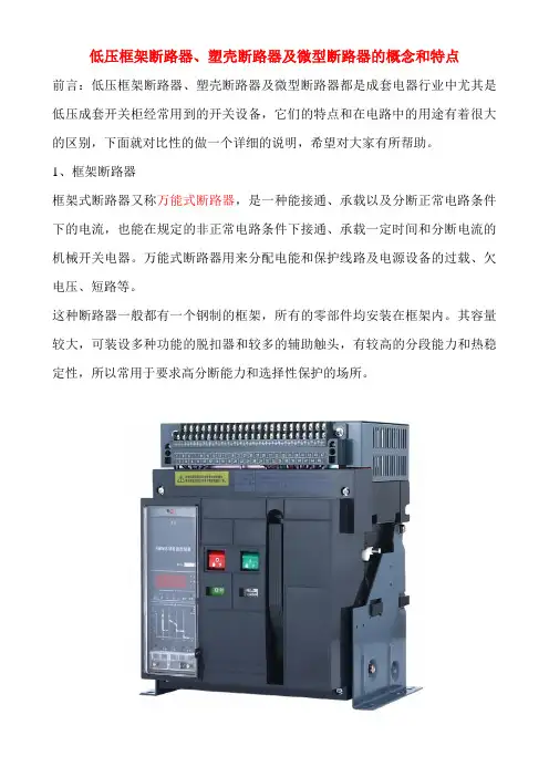
低压框架断路器、塑壳断路器及微型断路器的概念和特点前言:低压框架断路器、塑壳断路器及微型断路器都是成套电器行业中尤其是低压成套开关柜经常用到的开关设备,它们的特点和在电路中的用途有着很大的区别,下面就对比性的做一个详细的说明,希望对大家有所帮助。
1、框架断路器框架式断路器又称万能式断路器,是一种能接通、承载以及分断正常电路条件下的电流,也能在规定的非正常电路条件下接通、承载一定时间和分断电流的机械开关电器。
万能式断路器用来分配电能和保护线路及电源设备的过载、欠电压、短路等。
这种断路器一般都有一个钢制的框架,所有的零部件均安装在框架内。
其容量较大,可装设多种功能的脱扣器和较多的辅助触头,有较高的分段能力和热稳定性,所以常用于要求高分断能力和选择性保护的场所。
塑壳断路器也被称为装置式断路器,所有的零件都密封于塑料外壳中,辅助触点,欠电压脱扣器以及分励脱扣器等多采用模块化。
由于结构非常紧凑,塑壳断路器基本无法检修。
其多采用手动操作,大容量可选择电动分合。
由于电子式过电流脱扣器的应用,塑壳断路器也可分为A类和B类两种,B类具有良好的三段保护特性,但由于价格因素,采用热磁式脱扣器的A类产品的市场占有率更高。
塑壳断路器是将触头、灭弧室、脱扣器和操作机构等都装在一个塑料外壳内,一般不考虑维修,适用于作支路的保护开关,过电流脱扣器有热磁式和电子式两种,一般热磁式塑壳断路器为非选择性断路器,仅有过载长延时及短路瞬时两种保护方式,电子式塑壳断路器有过载长延时、短路短延时、短路瞬时和接地故障四种保护功能。
部分电子式塑壳断路器新推出的产品还带有区域选择性连锁功能。
大多数塑壳断路器为手动操作,也有部分带电动机操作机构。
小型断路器(英文名称:Miniature Circuit Breaker)又称微型断路器(Micro Circuit Breaker),适用于交流50/60Hz额定电压230/400V,额定电流至125A线路的过载和短路保护之用,也可以在正常情况下作为线路的不频繁操作转换之用。

欧姆龙枚举类型举例欧姆龙是一家全球领先的电子元器件制造商,在各种产品线中都有广泛的枚举类型。
以下是一些欧姆龙枚举类型的举例。
1.开关类型枚举:-机械开关:欧姆龙的机械开关系列包括微型开关、推动式开关、滑动开关等。
微型开关常用于家电、电子设备等领域,推动式开关常用于电动工具、汽车等领域。
-触摸开关:欧姆龙的触摸开关系列包括电容式触摸开关、防护装置、航天用触摸开关等。
电容式触摸开关常用于家用电器、工业控制设备等领域。
-光电开关:欧姆龙的光电开关系列包括光电开关传感器、光纤光电开关等。
光电开关常用于自动化控制、物流等领域。
2.传感器类型枚举:-温度传感器:欧姆龙的温度传感器系列包括热敏电阻、红外温度传感器等。
热敏电阻常用于温度测量与控制,红外温度传感器常用于非接触式温度测量。
-压力传感器:欧姆龙的压力传感器系列包括电容压力传感器、压电压力传感器等。
电容压力传感器常用于医疗设备、工业自动化等领域。
-位移传感器:欧姆龙的位移传感器系列包括光电式位移传感器、接近开关传感器等。
光电式位移传感器常用于流体控制、机械加工等领域。
3.控制器类型枚举:-逻辑控制器:欧姆龙的逻辑控制器系列包括PLC(可编程逻辑控制器)等。
PLC常用于自动化设备、工业机械等领域,用于控制各种工作流程。
-人机界面控制器:欧姆龙的人机界面控制器系列包括触摸屏、可编程终端等。
触摸屏常用于机床、打印机、自动售货机等领域。
-温度控制器:欧姆龙的温度控制器系列包括温度控制器、温度传感器控制器等。
温度控制器常用于加热设备、烘干设备等领域。
4.计数器/定时器类型枚举:-计数器:欧姆龙的计数器系列包括总计数器、短时计数器等。
总计数器常用于工业自动化、仪器仪表等领域,短时计数器常用于机械设备等领域。
-定时器:欧姆龙的定时器系列包括可编程定时器、时间继电器等。
可编程定时器常用于自动控制、电器设备等领域。
5.继电器类型枚举:-电磁继电器:欧姆龙的电磁继电器系列包括PCB继电器、模块继电器等。
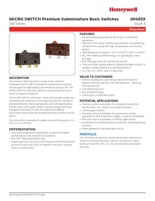
MICRO SWITCH Premium Subminiature Basic SwitchesSM SeriesDESCRIPTIONThe industry-defining name in snap-action switches,Honeywell MICRO SWITCH premium subminiature switches are designed for repeatability and enhanced product life. The MICRO SWITCH SM Series delivers consistent performance within a range of conditions.The MICRO SWITCH SM Series’ small size and light weight are combined with ample electrical capacity, precision operation, and extended life. Featuring high precision and repeatability, the SM Series offers gold contacts for low-energy switching and gold bifurcated contacts for maximum reliability.Bifurcated contacts provide parallel redundancy within the SM switch.The SM switch is available for power-duty switching up to 11 A (Vac) or 1/4 HP (Vac).DIFFERENTIATION• Very wide temperature range allows for years of reliable performance in the harshest of conditions • MIL-PRF-8805 qualified listings• Operating forces as low as 0,06 N [6 g] and differential travel as low as 0,025 mm [0.001 in] delivers consistent, precise switch characteristicsFEATURES• Industry-leading mechanical life of up to 10,000,000 operations• Selection of actuation, electrical termination, and operating characteristics along with high-temperature construction options• Wide temperature range of -54°C to 204°C [-65°F to 400°F]• MIL-PRF-8805 qualified listings in a lightweight, small package• FAA-PMA approvals for commercial aircraft• Choice of silver or gold-plated, or gold bifurcated contacts to handle a variety of electrical load requirements • UL/CSA, cUL, ENEC, and CE approvalsVALUE TO CUSTOMERS• Industry-leading life cycle rating reduces the need to replace switches over life in an OEM platform – reducing total system cost • Low operating forces • Mil-qualified listings• Life of up to 10,000,000 cyclesPOTENTIAL APPLICATIONS• Precision switch assemblies for commercial aircraft to monitor doors for “closed” and “locked” position • Landing gear monitor• Precision switch assemblies for commercial cockpitapplications for pushbuttons, toggle, or joystick assemblies • Precision switch assemblies in military applications• Assemblies for industrial pressure switches and temperature switches• Power generation fuel level (gas and oil)PORTFOLIOThe SM Series of premium subminiature basic switches are a part of a strong offering of submins including SX Series (premium) and ZM, ZM1, ZD, ZX, and ZW Series (standard) switches.Sensing and Internet of Things004959Issue 3Electrical data and UL codes2 * except where stated ±0,38 mm [±0.015 in]Sensing and Internet of Things 34 Sensing and Internet of Things 5Table 5. Numeric Designations for MICRO SWITCH SM Series/Order Guide6 Table 6. SM Series • Standard Actuator Options, Screw Terminals, and Dimensions (mm/in)Pin plunger, T terminalsPin plunger, Solder terminalsIntegral leaf leverIntegral roller leverIntegral leversNOTE: The two mounting holes accept pins or screws of 2,21 mm (0.087 in) maximum diameterMounting torque:0,26 Nm [2.3 in-lb] max.MICRO SWITCH SM SERIES AVAILABLE TERMINALSSensing and Internet of Things 7MICRO SWITCH JS SERIES AUXILIARY ACTUATORS FOR THE MICRO SWITCH SM SERIES SWITCH-ES (stainless steel actuator and hardware)** Travel characteristics on tandem actuators vary with actual basic switch characteristics NOTE: Above actuators should be used below 300°F* “A” measurement is from pivot point of lever to the point indicated on drawing DPlated steel machine screwsWarranty/RemedyHoneywell warrants goods of its manufacture as being free of defective materials and faulty workmanship during the appli-cable warranty period. Honeywell’s standard product warranty applies unless agreed to otherwise by Honeywell in writing; please refer to your order acknowledgement or consult your local sales office for specific warranty details. If warrantedgoods are returned to Honeywell during the period of coverage, Honeywell will repair or replace, at its option, without charge those items that Honeywell, in its sole discretion, finds defec-tive. The foregoing is buyer’s sole remedy and is in lieu of all other warranties, expressed or implied, including those of merchantability and fitness for a particular purpose. In no event shall Honeywell be liable for consequential, special, or indirect damages.While Honeywell may provide application assistance personally, through our literature and the Honeywell web site, it is buyer’s sole responsibility to determine the suitability of the product in the application.Specifications may change without notice. The information we supply is believed to be accurate and reliable as of this writing. However, Honeywell assumes no responsibility for its use.004959-3-EN IL50 GLO December 2016© 2016 Honeywell International Inc. All rights reserved.m WARNINGPERSONAL INJURYDO NOT USE these products as safety or emergency stop devices or in any other application where failure of the product could result in personal injury.Failure to comply with these instructions could result in death or serious injury.m WARNINGMISUSE OF DOCUMENTATION• The information presented in this product sheet is for reference only. Do not use this document as a product installation guide.•Complete installation, operation, and maintenanceinformation is provided in the instructions supplied with each product.Failure to comply with these instructions could result in death or serious injury.Find out moreHoneywell serves its customers through a worldwide network of sales offices and distributors. For application assistance, cur-rent specifications, pricing or name of the nearest Authorized Distributor, contact your local sales office.To learn more about Honey-well’s sensing and switching products,call +1-815-235-6847 or 1-800-537-6945,visit , or e-mail inquiries to *********************ADDITIONAL MATERIALSThe following associated literature is available at :• Product installation instructions • Product range guide • Aerospace range guide • Applying basic switches • Low energy switching guide• Product application-specific information – A pplication Note: Central Vacuum System – A pplication Note: Electronic Taping Machine– Application Note: Sensors and Switches in Sanitary Valves – Application Note: Sensors and Switches in Oil Rig Applications– Application Note: Sensors and Switches for Potential Medical ApplicationsHoneywell Sensing and Internet of Things 9680 Old Bailes Road Fort Mill, SC 29707 。

鼠标开关原理
鼠标开关原理是指鼠标在开关上按下时所产生的电信号,用来控制鼠标的开启和关闭。
在鼠标中,通常使用的开关是微动开关,即微型按钮开关。
微动开关由一个弹簧和一个接触片组成。
当鼠标按钮按下时,弹簧会被按压,从而使得接触片与触点连接,闭合电路。
这样,电流就可以通过开关流过,将信号传送到计算机。
当鼠标按钮松开时,弹簧恢复原状,使得接触片与触点分离,断开电路,此时电流不再流通,鼠标开关处于关闭状态。
鼠标开关原理的实现可以采用多种电子元件和技术,但微动开关是最为常见和可靠的一种。
由于微动开关结构简单,触发灵敏,且寿命较长,所以在鼠标设计中被广泛应用。
除了微动开关外,也有些鼠标采用其他类型的开关,比如光电开关。
光电开关利用光电传感器的原理,通过光束的遮挡来判断按钮是否被按下。
当鼠标按钮按下时,手指会遮挡住光束,使得光电传感器探测到光信号的改变。
这样就可以通过改变光电传感器的输出信号来控制开关的状态。
总的来说,鼠标开关原理就是通过按下或松开按钮来改变电路的通断状态,从而实现鼠标的开启和关闭。
而微动开关和光电开关是两种常见的应用在鼠标中的开关结构。

型号举例:5SJ62637CR
5SJ------产品系列号
SJ-------断路器系列 SJ为常规微型断路器 SY为紧凑型微型断路器 TE为隔离开关 SU为带漏电保护微型断路器 SD为带浪涌保护的微型断路器
6--------产品审测号
2--------极数还有1、2、3
63-------电流大小,另外还有0.5 1 2 4 6 10 13 16 20 25 32 40 50 63A
7CR-----国内工厂生产代号
艾驰商城是国内最专业的MRO工业品网购平台,正品现货、优势价格、迅捷配送,是一站式采购的工业品商城!具有 10年工业用品电子商务领域研究,以强大的信息通道建设的优势,以及依托线下贸易交易市场在工业用品行业上游供应链的整合能力,为广大的用户提供了传感器、图尔克传感器、变频器、断路器、继电器、PLC、工控机、仪器仪表、气缸、五金工具、伺服电机、劳保用品等一系列自动化的工控产品。
如需进一步了解相关断路器产品的选型,报价,采购,参数,图片,批发等信息,请关注艾驰商城。
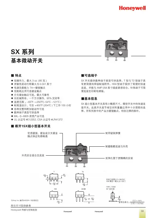
■ 特点◆ 低操作力,最大3 oz. (85 克)◆ 灵敏低差动行程最大为0.001英寸◆ 电源负载能力7A—镀银触点◆ 低能耗应用可选镀金触点◆ 分叉镀金触点可选,最大可靠性◆ 长机械寿命,一千万次操作,95%完好率◆ 温度范围 :-65o F~+250o F(-54℃~121℃)◆ 耐高温设计,可在+400o F (204℃)下工作100小时◆ 各种完整和附加驱动件可选◆ 数种端子类型可供选择◆ MIL-S-8805资质产品可选◆ UL 认证号#E12252, CSA 认证号#LR41372■ 断开1SX超小型基本开关■可选端子SX 开关提供数种端子类型可供选择。
T 型与T2型端子具有更简便的焊接配线附件。
H58型端子提供了简便的快速连接,并能与AMP.058英寸插座紧密结合。
针角端子可简便连接至印刷电路板。
■基本信息SX 超小型基本开关具有小精度尺寸,微型开关中的快速连接开关。
此类开关是节省空间和重量应用中十分理想的选择。
所有列表中的产品为镀银触点,特别注释的除外。
耐用铍铜弹簧耐磨酚醛底座与外壳延伸孔便于更精确的安装外壳安全接合至底座与Amp Inc.编号640024-1标准结合安装力矩圆头2-56UNC 438螺丝—最大为2英寸H391, H39290o 型针脚0,0 = mm 0.00 = inches单位表示:■针脚柱塞■订购指南(根据电气负载能力上升排列)Dim. Dwg. 图1(91SX39-T 和 93SX34-T 图2除外)■完整摆杆■订购指南特性:O.F.-动作力;R.F.-释放力;P.T.-预行程;O.T.-超行程;D.T.-差动行程;O.P.-操作位置Dim. Dwg. 图3Dim. Dwg. 图3Dim. Dwg. 图4Dim. Dwg. 图5Dim. Dwg. 图6311SX2-T(24.5mm)直摆杆5 Amps A 0.310.05 2.920.640.898.26±1.91313SX2-T 同上,带镀金触点1 Amp D0.310.052.920.640.898.26±1.91311SX3-T(24.5mm)直摆杆5 Amps A 0.200.03 4.700.61 1.527.75±2.92313SX3-T 同上,带镀金触点1 Amp D0.200.034.700.611.527.75±2.92311SX4-T(1.1mm)模拟滚轮摆杆5 Amps A 0.580.11 1.270.250.3814.15±0.91313SX4-T 同上,带镀金触点1 Amp D0.580.111.270.250.3814.15±0.91311SX5-T(11.7mm)模拟滚轮摆杆5 Amps A 0.310.05 2.670.560.8914.86±1.65313SX5-T 同上,带镀金触点1 Amp D0.310.052.670.560.8914.86±1.65■附加驱动件■订购指南特性:O.F.-动作力;R.F.-释放力;P.T.-预行程;O.T.-超行程;D.T.-差动行程;O.P.-操作位置; F.P.-自由位置*所有特性适用于如下所示1SX-T 装配的驱动件Dim. Dwg. 图7Dim. Dwg. 图8Dim. Dwg. 图9Dim. Dwg. 图9Dim. Dwg. 图10**开关与柱塞末端JX-40反转安装。
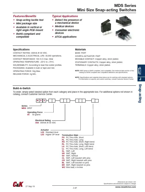
Snap-actingMDS SeriesMini Size Snap-acting SwitchesFeatures/Benefits • S nap-acting tactile feel • M ini package size • A vailable in vertical orright angle PCB mount • R oHS compliant andcompatibleTypical Applications• D etect the presence ofa mechanical device• Medical devices•C onsumer electronicdevices•A TCA applicationsSpecificationsCONTACT RATING: 300mA @ 30 VDC.MECHANICAL & ELECTRICAL LIFE: 30,000 operations.CONTACT RESISTANCE: 100 m Ω max. inital OPERATING TEMPERATURE: –25ºC to +70ºC.SOLDERABILITY: According to lead free solder profiles.PACKAGING: Available in bulk or tape and reel.OPERATING FORCE: 50g Max.RELEASE FORCE: 3g Min.MaterialsBASE: PA9TCOVER & ACTUATOR: PA9TMOVABLE CONTACT: Copper alloy, silver plated.STATIONARY CONTACTS: Copper alloy, silver plated.TERMINALS: Copper alloy, silver plated.NOTE: MDS series is RoHS compliant, and compatible. See technical data section of thiscatalog for RoHS compliant and compatible definitions and specifications.NOTE: Specifications and materials listed above are for switches with standard options.For information on specific and custom switches, consult Customer Service Center.Build-A-SwitchTo order, simply select desired option from each category and place in the appropriate box. For additional options not shown in catalog, consult Customer Service Center.SeriesMDS SPDTElectrical Rating00A 300mA @ 30 VDCOperating Force 65 50 gramsActuatorL02 Standard lever L03 Higher OP leverTermination StylePS PC Thru-hole, Short PL PC Thru-hole, LongRS PC Thru-hole, Short, Right bend RLPC Thru-hole, Long, Right bend LS PC Thru-hole, Short, Left bend LL PC Thru-hole, Long, Left bend SL SMT, Left SR SMT, Right SV SMT, VerticalCL SMT, Left bracket with pins CR SMT, Right bracket with pins BL SMT, Left bracket no pins BR SMT, Right bracket no pins WC Wire lead, 6 inchesACTUATOR MDS SeriesMini Size Snap-acting SwitchesSnap-actinL02 STANDARD LEVER L03 HIGHER OP LEVERSnap-actingMDS SeriesRS PC THRU-HOLE, SHORT RIGHT BEND PC THRU-HOLE, LONG RIGHT BENDPC THRU-HOLE, SHORT LEFT BEND PC THRU-HOLE, LONG LEFT BENDPS PC THRU-HOLE, SHORT STRAIGHT PL PC THRU-HOLE, LONG STRAIGHT2,5±0,082,5±0,08PCB MOUNTINGPCB Mounting Pattern123X 1,52,52X 1,82,58,7MDS SeriesMini Size Snap-acting SwitchesSLSMT, LEFT MOUNTSR SMT, RIGHT MOUNT0.070(1,8)TYP0.060(1,5)TYP 0.098(2,5)TYPSMT Mounting Pattern 0.070(1,8)TYP0.060(1,5)TYP 0.098(2,5)TYPSMT Mounting PatternCL SMT, LEFT BRACKET WITH PINSSV SMT, VERTICAL3X 1,52,5TYP3,10,383X3X 0,53X 0,83X 1,33X 1,363X 1,259051,6 R E FCOPLANAR TO 0.1mm53X 2,73,53X2,72,5 TYP123X 1,52,52X 1,82,58,7Snap-actingMDS Series123X 1,82,52,5S n a p -a c t i n gMDS Series123X 1,82,52,5WC WIRE LEAD, 6 INCHES12,72,79,53SHRINK TUBING152,426 AWG UL 1007 WIRECOMNO NCSnap-actingMDS SeriesMini Size Snap-acting SwitchesS n a p -a c t i n gSMT, LEFT MOUNT SMT, RIGHT MOUNT Supplied in carrier tape meeting the EIA-481-2 standard for 24mm tape. 4 TYP2 TYP12TYP6TYP5.8PY T 3.5TYP 10.1TYP501.5 TYPPULLING-OUT DIRECTION OF THE TAPESV SMT, VERTICAL MOUNT。
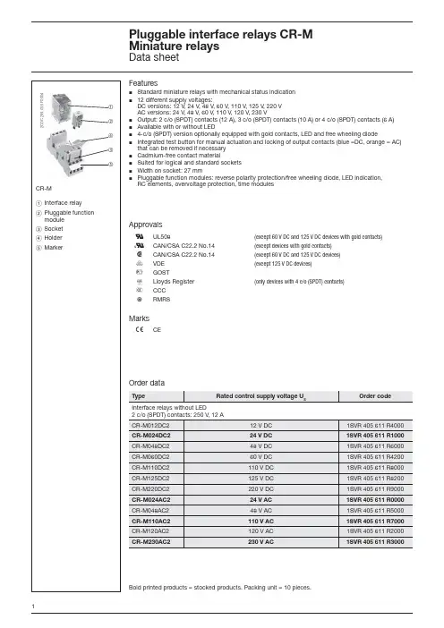
2C D C 293 035 F 000412435CR-MFeaturesStandard miniature relays with mechanical status indication ½ 12 different supply voltages:½DC versions: 12 V , 24 V , 48 V , 60 V , 110 V , 125 V , 220 V AC versions: 24 V , 48 V , 60 V , 110 V , 120 V , 230 VOutput: 2 c/o (SPDT) contacts (12 A), 3 c/o (SPDT) contacts (10 A) or 4 c/o (SPDT) contacts (6 A) ½ Available with or without LED½ 4-c/o (SPDT) version optionally equipped with gold contacts, LED and free wheeling diode½ Integrated test button for manual actuation and locking of output contacts (blue =DC, orange = AC) ½that can be removed if necessary Cadmium-free contact material½ Suited for logical and standard sockets ½ Width on socket: 27 mm½ Pluggable function modules: reverse polarity protection/free wheeling diode, LED indication, ½RC elements, overvoltage protection, time modulesᕃ Interface relay ᕄ Pluggable function module ᕅ Socket ᕆ Holder ᕇ MarkerOrder dataApprovalsG UL508(except 60 V DC and 125 V DC devices with gold contacts)O CAN/CSA C22.2 No.14(except devices with gold contacts)F CAN/CSA C22.2 No.14(except 60 V DC and 125 V DC devices)J VDE (except 125 V DC devices)D GOSTP Lloyds Register (only devices with 4 c/o (SPDT) contacts)E CCC LRMRSMarksaCEOrdering data - Accessories Function modulesTime modules2C D C 292 011 F 00042C D C 292 016 F 00042C D C 292 020 F 0004Connection diagramsCR-M with 2 c/o (SPDT) contacts A1-A2 Control supply voltage 11-12/14 Relay outputs 41-42/44CR-M with 4 c/o (SPDT) contacts A1-A2 Control supply voltage 11-12/14 Relay outputs 21-22/2431-32/34CR-M with 3 c/o (SPDT) contacts A1-A2 Control supply voltage 11-12/14 Relay outputs 21-22/2431-32/34ApplicationInterface relays are electromechanic and electronic input and output modules for electrical isolation, levelling, noise suppression or signal amplifi cation between control unit and process.Operating modeWhen power supply is applied, the output contacts get closed. When control supply voltage is switched off, the contacts fall back into their starting position. Manual operation and locking of the output relays is possible via the integrated test button.All CR-P/M modules - except time modules CR-P/M T... - can be plugged onto all CR-P or CR-M sockets. The time m odules CR-P/M T... can be plugged onto the following sockets only: CR-PLSx, CR-PLC and CR-M2LS, CR-M3LS, CR-M4LS, CR-M2LC, CR-M4LC.SocketsBold printed products = stocked products. Packing unit = 10 pieces.Technical dataLoad limit curves - Maximum switching power at resistive DC loadVersions with 2 c/o (SPDT) contacts (CR-M ... 2)Versions with 3 c/o (SPDT) contacts (CR-M ... 3)Versions with 4 c/o (SPDT) contacts (CR-M ... 4)2C D C 292 015 F 20042C D C 292 019 F 02042C D C 292 023 F 0204Technical diagrams2C D C 292 012 F 00042C D C 292 017 F 00042C D C 292 021 F 0004Reduction factor F at inductive AC load2C D C 292 014 F 2004Dimensions in mmVersions with 2 c/o (SPDT) contacts (CR-M ... 2)Versions with 2 c/o (SPDT) contacts (CR-M ... 2)Versions with 3 c/o (SPDT) contacts (CR-M ... 3)Versions with 4 c/o (SPDT) contacts (CR-M ... 4)2C D C 292 022 F 20042C D C 292 018 F 20042C D C 292 013 F 2004Load limit curves - Electrical lifetime at resistive AC loadFurther documentationTechnische Änderungen jederzeit vorbehalten. Alle Angaben dienen ausschließlich der Produktbeschreibung und sind nicht als zugesicherte Eigenschaften im Rechtssinne aufzufassen.r u c k s c h r i f t -N u m m e r : 2C D C 117 002 D 0104 (06/2009)Eppelheimer Strasse 82, 69123 Heidelberg, DeutschlandPostfach 10 16 80, 69006 Heidelberg, Deutschland Internet http://www.abb.de/stotz-kontakt Ǟ Schalt- und SteuerungstechnikDie Adresse Ihrer lokalen Vertriebsorganisation fi nden Sie auf der ABB Hompage unter /contacts Ǟ Low Voltage Products and SystemsAs part of the on-going product improvement, ABB reserves the right to modify the characteristics of the productsdescribed in this document. The information given is non-contractual. For further details please contact (/contacts) the ABB company marketing these products in your country.D o c u m e n t n u m b e r : 2C D C 117 002 D 0204 (06/2009)ABB STOTZ-KONTAKT GmbHEppelheimer Strasse 82, 69123 Heidelberg, Germany Postfach 10 16 80, 69006 Heidelberg, Germany Internet /lowvoltage Ǟ Control Products Contact: /contacts Ǟ Low Voltage Products and Systems。

2024年微动开关市场环境分析1. 概述微动开关是一种常见的电子元件,用于控制电子设备的开关动作。
它具有结构简单、可靠性高、使用寿命长等特点,被广泛应用于电子产品、通信设备、家用电器等领域。
本文将对微动开关的市场环境进行分析,包括市场规模、竞争格局、应用领域等方面。
2. 市场规模微动开关市场在近年来呈现稳定增长的趋势。
随着科技的进步和消费电子产品的普及,对微动开关需求不断增加。
根据市场研究数据显示,全球微动开关市场规模预计将达到XX亿美元,年复合增长率为X.X%。
3. 市场竞争格局微动开关市场竞争激烈,主要有以下几大厂商占据主导地位:1.厂商A:拥有多年的微动开关生产经验,产品质量可靠,市场份额占比约为30%。
2.厂商B:技术实力强大,研发能力突出,产品设计创新,市场份额占比约为25%。
3.厂商C:在市场中拥有较高的知名度和品牌影响力,产品价格相对较高,市场份额占比约为20%。
此外,还存在一些中小型企业,其市场份额相对较小,但仍有一定竞争力。
市场竞争格局相对稳定,大厂商通过不断推出新产品和做好售后服务,保持市场竞争优势。
4. 应用领域微动开关在各个行业领域都有广泛的应用,主要包括以下几个方面:1.电子产品:微动开关是电子产品中的重要组成部分,如手机、平板电脑、数码相机等。
随着消费电子产品的普及和更新换代速度的加快,对微动开关的需求也在持续增长。
2.通信设备:微动开关在通信设备中用于控制开关动作,保证设备的正常运行和通信质量。
随着5G技术的快速发展,对微动开关的需求将进一步增加。
3.家用电器:微动开关广泛应用于家用电器中,如电视、洗衣机、空调等。
随着人们对智能家居的需求增加,对微动开关的需求也呈现增长趋势。
5. 市场发展趋势未来微动开关市场将出现以下几个发展趋势:1.小型化和微型化:随着电子设备的迷你化趋势,对微动开关的需求将越来越倾向于小型和微型开关。
厂商需要不断优化产品结构和设计,满足市场需求。
R o ck erModels AvailableFeatures/Benefits• C ompact size—small footprint • S ingle and double pole models • P C and panel mounting options available •R oHS compliantTypical Applications • T elecommunications • Instrumentation • Medical EquipmentSpecificationsCONTACT RATING: Q contact material (TX01 models): 3 AMPS @120 V AC or 28 V DC. All other models: 2 AMPS @ 120 V AC or 28 V DC. See page G-49 for additional ratings.ELECTRICAL LIFE: TX01 models: 60,000 make-and-breakcycles at full load. All other models: 30,000 cycles.CONTACT RESISTANCE: Below 20 m Ω typ. initial @2–4 V DC, 100 mA, for both silver and gold plated contacts.INSULATION RESISTANCE: 109 Ω min.DIELECTRIC STRENGTH: 1000 Vrms min. @ sea level.OPERATING TEMPERATURE: –30ºC to 85ºC.SOLDERABILITY: Per MIL-STD-202F method 208D, orEIA RS-186E method 9 (1 hour steam aging).NOTE: Any models supplied with B, G, P, Q or R contact material are RoHS compliant. NOTE : Specifications and materials listed above are for switches with standard options. For information on specific and custom switches, consult Customer Service Center.MaterialsCASE: Glass filled nylon 6/6, flame retardant, heat stabilized ordiallyl phthalate (DAP), (UL 94V-0) or glass filled nylon 4/6, flame retardant, heat stabilized.ACTUATOR: Nylon, black standard.BUSHING: Brass, nickel plated.HOUSING: Stainless steel.SWITCH SUPPORT: Brass, matte-tin plated.MOUNTING BRACKET: Stainless steel.END CONTACTS: B contact material: Copper alloy, with gold plateover nickel plate. Q contact material: Coin silver, silver plated. See page G-49 for additional contact materials.CENTER CONTACTS & TERMINALS: B contact material: Copper alloy,with gold plate over nickel plate. Q contact material: Copper alloy, silver plated. See page G-49 for additional contact materials.TERMINAL SEAL: Epoxy.HARDWARE: Nut, Screws & Lockwasher: Stainless steel.Standoff: Nylon standard.Build-A-SwitchTo order, simply select desired option from each category and place in the appropriate box. Available options are shown and described on pages G-46 through G-50. For additional options not shown in catalog, consult Customer Service Center.All models have epoxy terminal seal and are compatible with all “bottom-wash” PCB cleaning methods.Switch Function T101 SP On-None-On T102 SP Off-None-On T103 SP On-Off-OnT105 SP Mom.-Off-Mom. T107 SP On-Off-Mom. T201 DP On-None-On T205 DP Mom.-Off-Mom.ActuatorJ1Rocker, .300” wide J6 Rocker, .230” wide TerminationsA Right angle, PC thru-holeAV Vertical Right angle, PC thru-hole Z Solder lugV3 V-bracketContact Material B GoldP Gold, matte-tin Q SilverG Gold over silverR Gold over silver, matte-tinSeal E EpoxyActuator Color 2 BlackRockerMOM. = Momentary All modelswith all options when ordered with G, Q or R contact material.R o c k e rPC MOUNTINGSP DPA RIGHT ANGLE, PC THRU-HOLEZ SOLDER LUGSP and DPT101J6ABE2 Horizontal ActuationSPDTNot available with P or R contact material.Not available with T102 model. J6 actuator standard only on T10X models with A terminations.V3 VERTICAL MOUNT, V-BRACKETAV VERTICAL RIGHT ANGLE, PC THRU-HOLEAV VERTICAL RIGHT ANGLE, PC THRU-HOLEA RIGHT ANGLE, PC THRU-HOLET201J1ABE2Horizontal ActuationDPDTT101J1AVBE2Vertical ActuationSPDTT201J1AVBE2Vertical ActuationDPDTT101J1V3BE2SPDTR o c k e rV3 VERTICAL MOUNT, V-BRACKET* Note: See Technical Data section of this catalog for RoHS compliant and compatible definitions and specifications.1 CONTACTS & TERMINALS: Copper alloy, with gold plate over nickel plate.2 END CONTACTS: Coin silver, with gold plate over nickel plate.3 C ENTER CONTACTS & ALL TERMINALS: Copper alloy, with gold plate over nickel plate.4 END CONTACTS: Coin silver, silver plated.5 CENTER CONTACT & ALL TERMINALS: Copper alloy, silver plated.6 TERMINALS: Copper alloy, with matte-tin over nickel plate.NOTE: Any models supplied with B, G, P, Q & R contact material are RoHS compliant. All modelswith all options when ordered with G, Q, or R contact material.B contact material standard with A, AV, V3 terminations.Q contact material standard withC & Z terminations.P & R contact materials not available with Z terminations.EPOXY SEALT201J1V3BE2DPDTRockerNOTE: Other colors, custom actuator markings and legends available, consult Customer Service Center.NOTE: Additional nuts, screws and lockwashers available separately, see Technical Data section of this catalog.TYPICAL ASSEMBLYPANEL THICKNESSPanel mounting hardware for rocker and lever handle switches is available separately. Mounting hardware consists of two screws, two nuts, two standoffs and two lockwashers per switch, and is available for panel thicknesses of 1/16, 3/32 and 1/8 inch. See part numbers below.。
V7-1A17D8-048V7-1C17D8-207V7-1C17E9V7-1C27E9V7-1S17D8 V7-2B17D8-201V7-5F17D8V7-6B19D8-057V7-1A17D8-057V7-7B19E9MICRO SWITCH™Premium Miniature Basic Switches Datasheet2What makes our switches better?Certified with CSA, ENEC, and UL for global acceptability Reliable snap-spring mechanism with more than 60 years ofproven service Available with pin plungers, integral levers (fitted two posi-tions), or auxiliary levers to meet equipment requirements Electrical ratings from 0.1 A up to 25 A fordesign flexibility in one package sizeMICRO SWITCH™ V7 SeriesPremium Miniature Basic SwitchesHoneywell’s MICRO SWITCH™ V7 miniature switches are designed for long term-reliability in a rugged switchpackaged with a thermoplastic housing. These switches may be installed in a wide range of applications from simple or precision on/off limits, presence/absence sensing, or embedded in pressure or temperature assemblies.The V7 switch is available as a pin plunger style or with optional integral or auxiliary levers to actuate the switch and offer versatility in the application. The switch requires as little as 0,15 Newtons [approximately ½ ounce] to operate for extremely sensitive applications or an operating force of almost 4 Newtons [14 ounces] where higher forces are required. The V7 switch can reliably control logic level electrical loads from less than 0.1 A to power duty switching up to 25 A. Agency certifications for the MICRO SWITCH™ V7 switches are provided through CSA, ENEC, and UL for global use around the world.COST OPTIMIZATION • RELIABILITYPERFORMANCE • GLOBAL ACCEPTANCEBig performance in a small package.3Features and BenefitsACTUATION ON TIMEMICRO SWITCH™ V7 Series basic switches operate with forces as low as 15 g and carry options to increase to 397 g, and can thereby easily accommodate different actuator mechanisms.RELIABLE PERFORMANCE IN HARSH CONDITIONSSwitches feature industry-leading temperature ranges of -40 °C to 175 °C [-40 °F to 347 °F] to allow for years of reliable performance in harsh conditions.LONG LIFE CYCLE RATINGThe long life cycle rating (up to 10,000,000 cycles ) reduces the need to replace switches over the life of OEM platform applications, therefore reducing total system cost.DESIGN FLEXIBILITYAvailable with pin plungers, integral levers (fitted 2 positions), and auxiliary levers to meet a variety of equipment requirements, MICRO SWITCH™ V7 Series switches also boast electrical ratings from 0.1 A up to 25 A for design flexibility in one package size.Global acceptance: UL, CSA, ENECVENDING MACHINE MOTORSSwitch controls motors or solenoids in vending machines for dispensing of product.MICROWAVE DOOR INTERLOCKSwitch in door interlock of microwave that disconnects power if door opened.OVEN CLEANING LATCHSwitch in door latch for oven clean operation.PRESSURE SWITCH ASSEMBLYPressure switch senses incoming water pressure for power washer.Potential Applications4V7 SeriesPRODUCT NOMENCLATUREV7Switch Type 1Operating Force1Termination Style(Inches)5Electric ratings “W” x “X” only used with “A” Mounting Construction and vice versa 6European ENEC rating requires Mounting Construction code “9” or “0”Electrical Rating 3,6CV7 Series Miniature Circuitry CodeMounting/Construction 4,61Use only if this switch has a special feature.Could be any number.Special Designator7D8Lever Style 2North Europe ——MICRO SWITCH™ Premium Miniature Basic Switches1 Incandescent lamp rating2 XX(Y) - XX = max. rated resistive value in amps, and (Y) = max. rated inductive value in amps3 European ENEC rating requires Mounting Construction code “9” or “0”. See page four, Mounting Construction column5BZ/BA Type[0.87 in]*3,1 mm mtg holes[0.81 in]** 177 °C [350 °F]78V7 SeriesAVAILABLE TERMINALS Quick Connect (QC)D8 Terminals: 0.187 in wide x 0.020 in thick.E8 Terminals: 0.187 in wide x 0.020 in thick.E9 Terminals: 0.250 in wide x 0.032 in thick.Printed Circuit Board (PO2)These terminals interface with snap-on receptacles and other components from AMPMODU interconnection system.MICRO SWITCH™ Premium Miniature Basic SwitchesThis Honeywell datasheet supports the following MICRO SWITCH™ V7 Series Basic Switch ListingsV7-1C17D8-002 V7-1C37D855-002 V7-6C18D8-002 V7-1C27D855-002 V7-1C33D855-002 V7-1C39D8-002 V7-1C17E9-002V7-6C28E9-002V7-1B17D8-022 V7-1B19D8-022 V7-1C17D8-022 V7-3S17E9-022V7-6B19E9-022V7-1S17D8-022V7-2B17D8-022 V7-3S17D8-022V7-1B29P07-022 V7-1C18E9-022V7-3E17E9-022V7-2B27D8-022 V7-2S17D8-022V7-9W1AE9-022 V7-1Z19E9-022V7-2B17D8-048 V7-1V19E9-048V7-1C17D8-048 V7-1X2AD8-048 V7-9W1AE9-048 V7-1B17D8-048 V7-3S17D8-048V7-9W2AE9-048 V7-7B17D8-048 V7-1A17D8-048V7-2B29E9-048V7-2B19E9-048V7-6C18D8-048 V7-1B27D8-048 V71A17D8048V7-1C17D8-201 V7-7B17D8-201 V7-1C13D8-201 V7-2B17D8-201 V7-1C17E9-201V7-2S17D8-201V7-6B19E9-201V7-1S17D8-201V7-7B17D862-201 V7-1D19D8-201 V7-3A17D8-201V7-1D10E9-201V7-1V17D8-201V7-1C17D8-207V7-1B17D8-207V7-2B17D8-207V7-1C17E9-207V7-2A17D8-207V7-1V19E9-207V7-1B10E9-207V7-1A27D8-207V7-7D17D8-207V7-2S17D8-207V7-1S17D8-207V7-1C17D8-263V7-1B17D8-263V7-6C17D8-263V7-1Z10E9-263V7-1S17D8-263V7-1C27E9-263V7-1V29E9-263V7-3E19E9-263V71Z10E9-263V7-7B19D8-263V7-1S18D8-263V7-1B37D8-263V7-3A17D8-263V7-1B178-263V7-1A27D8-636V7-1C17D8V7-2B17D8V7-1V39E9V7-1Z19E9V7-1B37D8V7-2S17D8V7-1C17E9V7-1C37D8V7-1Z29E9V7-3E17D8V7-5F17D8V7-7B17D8V7-1S17D8V7-1V19E9V7-3E17E9V7-1Z20E9V7-4A17D8V7-5F27E9V7-1Y39E9V7-1V29E9V7-1D10D8V7-2B17E9V7-6C17D8V7-4S17D8V7-1Y19E9V7-1C27E9V71Z10E9V7-1B17D8V7-6B19D8V7-1C18D8V7-1A17D8V7-2B29D8V7-5D17E9V7-3A17D8V7-4S37D8V7-7B19E9V7-1Z10E9V7-2A17E9V7-5F27D8V7-3S17E9V7-1S10D8V7-1Z39E9V7-2B27E9V7-3E19E9V7-1A17P02V7-4S27D8V7-7B27D8V7-1Z13E9V7-1Z30E9V7-2A27D8V7-7A19D8V7-2B37E9V7-1C29D8V7-1C13E9V7-3A18D8V7-9W2AE9V7-4A18E9V7-9W1AE9V7-1A28D8V7-1B19E9V7-1K29E9V7-2B17-D8V7-3E10E8V7-6C37E9-036V7-1C27D94V7-1C17D8-295V7-1C29D7V7-1Z13E993V7-1V19E9-269V7-6C13D8-132V7-6B19D8-057V7-2B17D8-162V7-4A29E8-424V7-1C17D844V7-1B17D8-122V7-1C17D844-429V7-7A19D8-374V7-4A17D8-407V7-5F17D8-289V7-6C17D8-057V7-2B29D8-384V7-1X1AD8-304V7-6C17D8-162V7-1A23E9-172V7-1X2AD9C2V7-1C27E9-292V7-2S17E9-420V7-1C17D8-294V7-7B17D8-073V7-3S17D8-148V7-7C19D8-640V7-1V19E994-403V7-1A17D8-057V7-1E17D8-366V7-5F17D8-336V7-1C17E9-292V7-6A17D8-057V7-2E17E9-420V7-6C17D8-439V7-1X1AD9C1V7-7B10D8-274V7-7B19D8-426V7-3E17D8-148V7-1A28D882V7-7B29D883V7-7B17D8-481V7-2E17E9-366V7-1C29E7V7-1S19D8-369V7-7B19D8-640V7-7B17D8-140V7-1X2AE9-292V7-1Z13E987V7-1X2AD8-294V7-6B19D8-672V7-7B29E9-053V7-1V20E94V7-1B19D8-36915PA177-V715PA2609V7 SeriesADDITIONAL INFORMATIONThe following associated literature is available on the Honeywell web site at :• Product installation instructions• Product range guide• Product nomenclature tree• Product application-specific information– Application note: Electronic sensors and electromechanicalswitches in valves and flow meters– Application note: Electronic sensors and MICRO SWITCH ™switches in industrial air compressors– Application note: Sensors and switches for HVAC/Rapplications– Application note: Sensors and switches in oil rig applications– Application note: Sensors and switches in sanitary valves– Application note: Sensors and switches for valve monitors and valve indicators– Application note: Treadmill equipment– Application note: V7 available terminals– Technical bulletin: Applying precision switches– Technical bulletin: Low energy switch guideWARRANTY/REMEDYHoneywell warrants goods of its manufacture as being free of defective materials and faulty workmanship. Honeywell’s standard product warranty applies unless agreed to otherwise by Honeywell in writing; please refer to your order acknowledgement or consult your local sales office for specific warranty details. If warranted goods are returned to Honeywell during the period of coverage, Honeywell will repair or replace, at its option, without charge those items it finds defective. The foregoing is buyer’s sole remedy and is in lieu of all other warranties, expressed or implied, including those of merchantability and fitness for a particu-lar purpose. In no event shall Honeywell be liable for conse-quential, special, or indirect damages.While we provide application assistance personally, through our literature and the Honeywell website, it is up to the customer to determine the suitability of the product in the application. Specifications may change without notice. The information we supply is believed to be accurate and reliable as of this printing. However, we assume no responsibility for its use.004987-2-EN IL50 GLO January 2015Copyright © 2015 Honeywell International Inc. All rights reserved.Sensing and Control Honeywell1985 Douglas Drive North Golden Valley, MN 55422 Find out moreHoneywell serves its customers through a worldwide network of sales offices, representatives and distributors. For application assistance, current specifications, pricing or name of the nearest Authorized Distributor, contact your local sales office.To learn more about Honeywell’s sensing and control products, call +1-815-235-6847 or 1-800-537-6945,visit , or e-mail inquiries to *********************V7-1B17D8-048-S V7-7D17D8-207V7-1A17D8-057V7-1A17D8-048V7-1C17D8-207V7-1C17E9V7-1C27E9V7-1S17D8 V7-2B17D8-201V7-5F17D8V7-6B19D8-057V7-1A17D8-057V7-7B19E9。
小型断路器与漏电开关的区别小型断路器/微型断路器/小空开(英文名称:Miniature Circuit Breaker),电气行业简称为MCB,适用于交流50/60Hz额定电压230/400V,额定电流至63A线路的过载和短路保护之用,也可以在正常情况下作为线路的不频繁操作转换之用。
剩余电流保护断路器剩余电流保护装置(电气行业简称RCD),又称“漏电开关”,是一种利用检测被保护电网内所发生的相线对地漏电或触电电流的大小,而作为发出动作跳闸信号,并完成动作跳闸任务的保护电器。
在装设漏电保护器的低压电网中,正常情况下,电网相线对地泄漏电流(对于三相电网中则是不平衡泄漏电流)较小,达不到漏电保护器的动作电流值,因此漏电保护器不动作。
当被保护电网内发生漏电或人身触电等故障后,通过漏电保护器检测元件的电流达到其漏电或触电动作电流值时,则漏电保护器就会发生动作跳闸的指令,使其所控制的主电路开关动作跳闸,切断电源,从而完成漏电或触电保护的任务。
RCD具有过载和短路保护功能,可用来保护线路或电动机的过载和短路,亦可在正常情况下作为线路的不频繁转换启动之用。
小型断路器与剩余电流保护断路器(漏电开关)有何异同?二者都起线路过载保护作用。
小型断路器是控制电气回路的分合开关,若以空气为灭弧介质的称空气开关。
一般以额定电流(负荷)选择,做为电气回路的总开关使用。
漏电开关是集过载、短路和漏电保护于一体,可独立安装,相当于漏电保护器加小型断路器或漏电附件加小型断路器。
可以简单理解为当一个小型断路器带有漏电保护功能时,称之为漏电保护开关。
如果是一个单单用于漏电保护的电气装置,则称之为漏电保护器。
小型断路器B、C、D类脱扣特性有何区别?如何应用?B类的瞬时脱扣电流是3-5In(额定电流),适用于电阻性负载;C类的瞬时脱扣电流是5-10In,适用于一般负载;D类的瞬时脱扣电流是10-20In,适用于大电感性负载。
小型断路器把手合不上,为什么?先检查小型断路器输出回路有没有短路或过载情况发生。
微动开关
微动开关概述
微动开关通常有很多名称,包括“微型快动”开关。
本质上它们是使用“偏心”或端点机制,使用最小压力方便启动的电器开关。
由于造价低廉,使用寿命长,如今它们被工程师和电工广泛使用—尤其是用作可提供一百万次循环使用的单开关,而工业微动开关可循环使用一千万次。
相对于提供简单二态开/关状态的开关,微动开关通过为致动器提供在特定位置间灵活且可靠转换的能力,使其具有极高的灵活性。
在其核心,微动开关的主要特性是致动器按钮产生的放大:按钮的微小按压会产生触点间的较大(且极其迅速)移动。
即使致动相对缓慢,触点的移动始终十分迅速。
微动开关也根据其功能来定义:其能保持“目前状态”,直到致动器发生重大逆转。
这一被称为“迟滞现象”的发明,说明微小逆转不会引起动作。
当致动器受到必要逆转时,其提供了迅速且可靠切断的切换电路。
技术方面
微动开关的一种十分广泛的应用设计包括两个导电弹簧的内部使用。
第一个直的金属条弹簧,由位于开关一角的折页水平固定在另一角。
其是一组电器触点。
小的拱形弹簧(通常是钹铜(BeCu)材质),在装配过程中被置于压力之下,因此在开关外壳内,其总在试图伸直。
其与接近电器触点的又长又平的弹簧相连。
在片簧中心附近,置有一个支点,而一个可按压致动器小块与位于折页附近的片簧相接触。
弯曲弹簧努力将片簧拉离其折页锚点,而弯曲弹簧阻止此类移动。
其亦施力以将片簧从锚点向上拉,虽然几何结构保证这一力量与将片簧下拉时片簧的向下位移相称。
当致动器受开关外力按压时,其使片簧折曲,而触点被弯曲弹簧关闭。
但最终当片簧的折曲迫使弯曲弹簧压紧,这时电器触点开始分离。
即使致动器小块未进一步移动,弯曲弹簧向上的力按片簧的向下移动而降低,这一进展加速了片簧的移动,影响了常开触点。
当片簧下移时,其失去张力,但开关的设计方式是加速依旧是操作的净效应。
这就是前面提到的端点或偏心动作,且其导致明显的清脆感觉和可听到的咔哒声。
一旦释放致动器,片簧立即开始向上移动。
当其上移时,引起了弯曲弹簧施加的上移力。
结果再次导致加速,而当常闭触点接触时,该加速停止。
即使其导致片簧弯曲,弯曲弹簧被设计的足够有力以移动触点,因为在从下到上的转变过程中,致动器实际上并未移动。
虽然微动开关使用年限长,但是在开关的寿命中,拱形“回返”弹簧通常最先损坏。
在制造业中微动开关的用途
在工业和室内安装中,微动开关的应用十分广泛。
微波炉就是其中一例—微波炉门互锁装置提供开/关状态,也就是说当门打开时,微波炉将停止工作。
在其他方面,它们也被广泛用于电梯水平和安全开关。
在办公室安装中,微动开关是影印机纸张堵塞检测机制的一部分。
微动开关也在消防安全技术和灾难管理技术中
十分重要,其通常并入消防喷淋系统的门阀中(实际上用作防拆开关),当然它们也被用于许多水管系统中,其在确定阀门是否已被关闭或打开方面意义重大。
微动开关也是此目的的理想解决方案。
微动开关经典功能的一个例子,是其通常被用于控制不同电路,如自动售货机和工业控制的电路。
它们也可用来在控制电路中传输电流,虽然有些微动开关可以直接用来控制螺线管、灯具、小型电机和其他装置。
在工程角度,该技术的实际应用说明,比如,用来发售食物和饮料的装置的动作,可以被微动开关特殊设计的低力类型(可感应硬币)引起,其也可被用来感应发售机内的空气流动(当其与叶片连接时)。
虽然微动开关可在无中介的机制下运行,其用途也扩展到共同作为温度、流量和压力开关的一个成分。
这些通常通过感应机制,如波登管操作(该管遵守这一定律:在压力下,被压平的管将会恢复其循环形式)。
但在这些应用中,长期的准确性基本上依赖于开关时致动器的重复性。
计时器机制也经常使用微动开关,然而其通常被设计带有速度相对较慢的电动凸轮,以在此应用中正常运行。
除了其他用途外,微动开关的另一常见应用是用作控制电动机器或机械工具的限制开关:当并入此类装备中时,包括瞬动开关机制的金属外壳,以及带有致动柱塞、滚筒或杠杆,以实现其设计功能的开关。
微动开关与其他开关有何不同
微动开关与其他电器开关相区别的主要特征是:致动器微小移动的巨大放大,导致开关内的成型弹簧加速电子触点的打开与关闭,结果是触点十分迅速的分离或接触。
微动开关也能承受致动器极高程度的重复,使其比许多其他开关寿命更长。