艉轴空气型密封装置简介与管理要点
- 格式:doc
- 大小:442.00 KB
- 文档页数:2
船舶尾轴空气密封修船注意事项
1. 嘿,你知道吗,船舶尾轴空气密封修船的时候,一定要仔细检查密封件啊!就像你爱护自己的宝贝一样,可不能马虎!比如说,你总不会随便对待你心爱的手机吧?
2. 修船的时候,千万别忘了给尾轴来个全面的“体检”呀!这可关系到船舶的安全呢,就好比人的身体,一处小毛病都可能引发大问题,你说是不是?
3. 注意啦,在安装新的空气密封时,要像给公主穿新衣一样小心翼翼啊!你想想,要是不小心弄破了,那可就糟糕了,就像新衣服被扯坏了一样心疼。
4. 哎呀呀,修船师傅们可别粗心大意哦!对船舶尾轴空气密封的处理要格外用心,这可不是闹着玩的,好比建房子,根基不稳怎么行呢?
5. 大家在修船时,一定要确保密封安装到位啊!这就像给门安装锁一样,没安好可就不保险啦,你能放心吗?
6. 嘿,别忘了检查密封的周边环境呀!就像你出门要看看天气适不适合一样重要,要是有问题不及时处理,那后果不堪设想呢!
7. 修船的时候,对尾轴空气密封的每一个细节都不能放过啊!这就好像拼图,少一块都不行,你说对不对?
8. 注意哦,处理密封的时候动作要轻柔些呀!可别像个糙汉子似的,不然弄坏了可咋办,就像对待易碎的花瓶一样呀!
9. 哇塞,修船可真是个技术活呀!特别是船舶尾轴空气密封,一定要高度重视,这可关系到整艘船的命运呢,能不认真对待吗?
10. 最后啊,大家一定要牢记这些注意事项,把船舶尾轴空气密封修得妥妥当当的!让我们的船能安全航行,这多重要啊!
我的观点结论就是:船舶尾轴空气密封修船马虎不得,必须认真对待每一个细节,才能确保船舶的安全和正常运行。
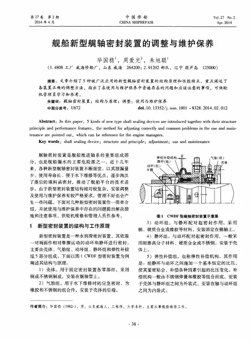
KOBELCO空气式尾轴密封KOBELCO空气式尾轴密封大连远洋公司船技部富强【内容提要】此文介绍KOBELCO空气式尾轴密封形式的基本设计,工作原理和基本组成,并借助图纸介绍安装此设备时的检查注意事项和密封检查方法.l简单介绍为防止海水污染,KOBELCO公司设计制造了空气式尾轴密封装置.该密封装置的艏部(FWD)密封结构与以往KOBELCO紧凑密封的结构相同,艉部()空气式轴封的结构如图1所示(P4型).图1AFT轴封的结构(P4型)该轴封是通过在金属外壳凸缘上方的空气喷管把空气放出,排进海水里.空气喷管是"止回"式的,一旦空气停止放出,海水也不会从喷管侵入.利用放出的空气来检测船舶吃水的变化,然后根据吃水的变化产生的压力,以调整空气流量与油管的油压,从而防止海水侵入船内和润滑油流出船外.同时,各密封环所承受的压力也减小而能保持良好性能.其特长为:(1)各密封环所承受的负荷量明显减小,同时,海水侧,轴管侧都有两根密封环装置,提高了可靠性.一旦密封环破损,船尾管内的润滑油或海水会通过空气室被收回到船内,不会有油流出船外或海水侵人尾轴管内的可能性;(2)维修保养简单,在设定了空气流量和2#/3#密封环之间的空气压力之后,操作系统自动化工作,避免了根据吃水的变化来转换油柜的操作方式;(3)空气消耗量较小,基本设定在40~60L/min;(4)如遇空气压力控制单元发生故障,只要备有重力油柜,便能将空气密封转变成普通的防油密封环.2基本设计船尾管内的管道为4根(P4型),位于顶部的排气管和通往NO.2/3之间的供气管的材质是铜管;位于底部的来自NO.2/3之间的排油回收管和NO.3/3s之间的供油管可以是铜管,也可以是不锈钢管.供气装置到空气密封装置之间的管道基本用铜管将空气供到空气控制单元.S/T油罐的容量由船尾管内的容量决定,大致数值如下表,油罐的设置在高出尾轴中心线3m左右的高度.轴封尺寸(ram)S/I"油罐的容量(L)670以下10071O以下2oo在紧急情况发生时,为了能够简单转换为旧式轴封,在S/T出口管上安装分歧管.回流管的高度应比海水水压高出0.2~0.3kg/cm.3工作原理该密封系统主要由以下部分组成:空气压力控制单元:用于控制和调节的压缩空气进入该单元,该装置内置的控制机件和设置在厂家出厂前已经调节完毕, 使用中仅仅检查阀门的开,关状态即可;油压单元:一般有2台齿轮油泵,一台保持连续运转,对油柜施加压力;海水和油回收单元:用于回收油水,该单元一般位于船底;S/T油柜:管道配置系统如图2所示.从图2可以看出,这种结构通过排气检验船舶吃水的变化,根据吃水的变化对密封环的空间和船尾轴油管施加最为合适的压力,从防止海水进人船内和滑油漏出船外.各部位的压力条件如表1所示:表1各部位的压力条件结构海水NO.1NO.2NO.3NO.4尾管油流体海水(滑滑油)空气油油1.O1.O1.O1.31.3压力kg/emkg/emkg/emkg/cmkg/em控制空气气压空气压+空气压+方法油压油压管道无供气#油油入口油入口/出口NO.2/3之间:从凸缘环上排气检测出海水压力,以此施加与海水压力相同的空气压力.进入NO.2/3 之间的海水或油,通过排油回收管被回收到船内.N0.1/2之间:没有安装来自船内的管道.因此,NO.1/2之间的压力几乎与海水压力相同.在此空间通常为海水与空气的混合状态.船尾轴管内:在轴心约施加0.25kg/cm油压的地方安装重力柜.对这个重力柜施加与海水压力同样的空气压力.KOBEI』c0空气式尾轴密封——富强NO.3/3S问:由于使用泵对船尾管重力油柜的油进行循环,因此压力与船尾管相同.4安装检查在新造船和拉尾轴的修理时,都会涉及到安装检查问题.无论在什么情况下,管系和各个单元的安装已经完毕,主要检查各个装置与空气式轴封的连接是否正确,空气控制装置的接头都有编号,按照编号对照连接部位没有错误即可.因此,管理人员检查的重点是管系的清洁和密封情况.一般在安装轴封前,必须用压缩空气冲洗循环油管和空气管.此后,对各个部位密封试验认真检查.密封检查分两个主要部分:(1)空气管和循环油管的泄漏试验a)从船尾隔壁到船尾轮毂之问的管道试验方法,用塞子插在轮毂放气出口,即关闭此出口,然后向管内提供约3.0kg/cm的空气压力,在10分钟内不可有压力明显下降的现象,检查后,务必拔出塞子.b)空气管泄漏试验,来自空气控制装置的空气压力已经经过减压阀调整,从空气控制装置向管路供约3.0kg/cm的空气压力,检查以下各项:①排气管(仅限P4型)检查压力下降情况,进行10分钟左右.②关闭NO.2/3之间人口管路上的阀门,使用空气控制装置P5压力表进行检查,进行1O分钟左右.③在管道接头部位抹肥皂水,检查有无漏泄.C)循环油管泄漏试验,向尾轴管和NO.3/3s之间加油后,施加相当于应急时使用S/T重力柜的压力, 检察管道接头部位有无漏油..(2)船尾管和轴封装置的供油及密封试验a)船尾管的供油及NO.3s密封环的泄漏,给船尾管加油,然后转换到应急用S/T油柜的循环油管上(操作方法参阅使用说明书和管道系统图).注意先不要向NO.3/3s之间加油.取下船尾轴封装置NO.3/3s 之间的插塞,检查从NO.3s密封环处有无漏油.b)NO.3/3s之间的供油和NO.3密封环的漏泄图2试验,①插上船尾密封装置NO.3/3s之问底部的插塞,取下顶部的插塞.②打开No.3/3s之间管道上的阀门,向此空问加油,加到顶部时停止加油,然后检查NO.3密封环有无漏油.检查方法有两个,其一,从NO.3/3s之问的顶部插塞处检查NO.3/3s之问油空间的油面有无下降,试验结果1O分钟不下降为好.其二,插上N0.3/3s之问顶部的插塞,施加应急时用S/ T重力柜的油压.取下NO.2/3之问底部的插塞,检查NO.3密封环处有无漏油.c)前侧轴封的供油及漏泄试验,这与以往油封式轴封的检查相同.①向船尾管加油后,取下艏密封NO.4/5之问底部的插塞,检查从N0.4密封环处有无漏油.②检查NO.4密封环处没有漏油后,向No.4/5之间加油,加油后检查从NO.4密封环处有无向前侧漏油以及圆环处有无漏油.供油后到进水前以及进水后装机期间,注意千万不要从空气控制装置排气.5运转前的操作(1)按照说明书检查各个装置以及与其连接的管道上阀门的开关状态.(2)慢慢打开空气控制装置的空气总阀,开始供气.供气之前,必须将空气中的杂质排放掉.(3)后侧轴封装置的压力调整在设备厂家已经调整完毕.如发生与使用说明书所要求的压力条件不符时,应要求厂家进行调整.<航海技术)2004年第5期。
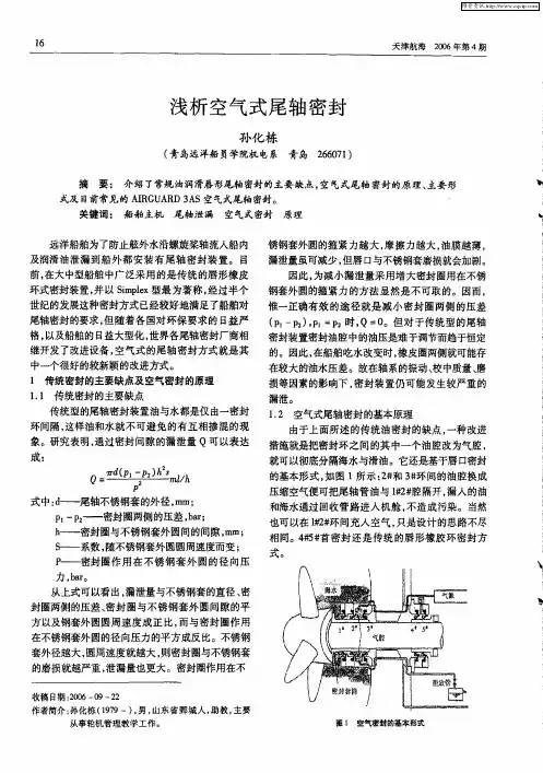
简述空气密封型艉轴密封装置的应用摘要:本文以ax型艉轴密封装置为例,简述空气密封型艉轴密封装置在现代船舶上的应用。
关键词:空气密封; ax型; 船舶abstract:this paper introduces the application of ax type air seal stern tube bearing system at modern ship. keywords:air seal;ax type;ship中图分类号:[o355] 文献标识码:a 文章编号:1 前言艉轴密封装置能保证艉轴在运转中有下沉、径向跳动及偏心转动、轴向窜动等情况时具有良好的密封性,有效隔离滑油和海水、泥沙,防止艉管滑油泄漏或是海水灌入机舱,所以艉轴密封装置工作性能的好坏,直接影响船舶能否正常营运。
目前新造的大中型舶船上广泛采用空气密封型艉轴密封装置,它是传统的“simplex”型艉轴密封装置的改进型,是目前比较先进的船舶艉轴密封装置。
本文以某新造远洋货轮为例,该轮设计吃水18.1米,船体基线至轴系中心线高度5米,安装了伊格尔工业株式会社-kemel公司生产的ax型艉轴密封装置,使用0.7mpa的压缩空气作为工作气源,冲洗水由船上的淡水压力柜供给。
结合实际情况,对ax型艉轴密封装置的结构特点、日常操作注意事项等进行介绍、分析。
2 ax型艉轴密封装置的特点和工作原理2.1 密封装置的特点ax型艉轴密封装置由前密封和后密封装置组成,具有其独特的优点,比如:1、可靠性和安全性高;2、结构紧凑并且易于操作;3、维护保养简便;4、空气消耗量少;5、带有防渔网功能,减少进坞维修费用;6、根据吃水自动调整压力,确保密封性能。
2.1.1 前密封装置图1所示,前密封装置的结构基本上与后密封装置相同,不同的是前密封装置只有#4、#5两道密封环。
密封环的作用是把滑油密封在艉管和轴承区域的油腔中,阻止滑油泄漏。
装置中的衬套通过螺栓上紧的夹紧环安装在艉轴上,随轴的旋转而转动。
船用艉轴密封
船用艉轴密封是一种用于船舶尾部轴承密封的装置,主要
用于防止海水进入船舶的机舱。
它通常由以下几个部分组成:
1. 艉轴密封壳体:密封壳体是安装在船舶艉部的一个金属
外壳,通常由高强度和耐腐蚀的材料制成,如不锈钢。
密
封壳体具有良好的密封性能,能够有效防止海水进入机舱。
2. 密封垫片:密封垫片是安装在密封壳体内部的一个重要
部件,通常由弹性材料制成,如橡胶。
密封垫片能够与轴
承紧密接触,并形成密封效果,防止海水渗入。
3. 密封油:密封油是填充在密封壳体内部的润滑油,通常
为高温、高压和耐腐蚀的润滑油。
密封油能够在轴承和密
封垫片之间形成一层润滑膜,减少摩擦和磨损,同时也能
起到密封作用。
4. 密封装置:密封装置包括密封环、密封垫、密封圈等,
用于确保密封的完整性和稳定性。
这些密封装置通常由耐
腐蚀和耐磨损的材料制成,如橡胶和金属。
船用艉轴密封的工作原理是,当轴承转动时,密封垫片与
轴承紧密接触,并形成一层密封效果。
同时,密封油在密
封壳体内形成一层润滑膜,减少摩擦和磨损。
当海水试图
进入机舱时,密封垫片和密封装置会阻止海水的渗入,保
持机舱的干燥和安全。
船用艉轴密封在船舶的设计和制造中起到了至关重要的作用,它能够有效保护船舶的机舱免受海水的侵蚀,提高船舶的安全性和可靠性。
同时,船用艉轴密封还能减少轴承的磨损和故障,延长轴承的使用寿命,降低维修和更换的成本。
船舶尾轴密封装置原理及漏泄处理一、引言船舶尾轴密封装置是船舶轴系的重要部件之一,其性能好坏直接影响到船舶的运行,同时对防止尾轴滑油污染海洋环境也起着十分重要的作用,因此对尾轴密封装置的研究是极其必要的。
笔者所在的船舶,大风浪天气航行时突发机舱尾轴密封油柜高位报警,后经检查发现,是尾轴密封不良导致海水漏泄至密封油腔里,引起密封油柜高位且乳化。
船舶尾轴密封油漏泄有两种情况常见:一是大风浪天气,船舶尾吃水小,由于船体剧烈震动,就会引起密封装置密封不好;二是船舶长时间锚泊,主机启动时有时会引起尾轴密封不好,从而导致漏泄。
尾轴密封不好导致漏泄一般分为:海水进入油腔造成密封油柜油乳化,最终导致尾轴腐蚀,或者密封油柜的油漏泄至船舷外,导致油污染水域。
无论哪种情况,都会造成不良的后果。
因此,必须重视船舶尾轴密封情况,一旦发生漏泄,就要及时采取正确措施。
二、船舶尾轴密封装置1.现代尾轴密封的特点目前海船的尾轴承绝大部分以油润滑的白合金轴承替代铁犁木等传统的水润滑轴承,其油膜承载能力大,油的润滑性能好,尤其是其密封装置能有效地密封,使海水和泥沙不易进入尾轴管,所以磨损很小,主机和轴系的工作相对平稳、可靠。
2.尾轴密封的结构尾轴密封装置分前密封装置(SC2Z)和后密封装置(SC2B)。
前密封装置位于机舱一端,其作用是防止尾轴管内的润滑油泄漏到机舱;后密封装置位于螺旋桨一端,其作用是既防止尾轴管内滑油泄漏到舷外污染海面,又防止海水进入尾轴管内乳化润滑油。
后密封装置一般有三道密封环(1号、2号和3号),后面两道密封环(1号、2号)的作用是防止海水进入尾轴管内,第三道密封环(3号) 的作用是防止尾轴管内滑油泄漏(见图1)。
前密封装置的结构与后密封装置的结构基本相同,不同的是前密封装置只有两道密封环(V1、V2)(见图2)。
密封环是由丁晴橡胶图2前密封装置的两道密封环(NBR)或氟橡胶(VITON)制成的,可根据不同的使用条件选择使用。
Advanced Technology of Propeller Shaft Stern Tube SealSeiji Yamajo , Dr. Eng.Iwao Matsuoka_____________________________________1Technical Director, KOBELCO MARINE ENGINEERING2-3-1, Shinhama Arai-cho, Takasago, 676-8670, Japan2KOBELCO MARINE ENGINEERING2-3-1, Shinhama Arai-cho, Takasago, 676-8670, JapanABSTRACTThe paper outlines the details concerning historical perspective and recent developments to meet a requirement that lube oil and seawater leakage must be prevented under any circumstances. Using a compressed air chamber, the lube oil in the stern tube is completely separated from seawater by providing a controlled “buffer zone” between lip type sealing rings. A constant quantity of compressed air supplied from within the ship, passes through the air chamber and is spouted into the sea. An air control unit automatically detects any change of draft level and adjusts the pressures to maintain the optimum pressure on each sealing ring. The key mechanism to detect the draft change correctly and to adjust the pressure balance is explained. Specific design and project applications for the stern tube air seal on ocean going and other marine vessels using line shaft propulsion and pod propulsion are explained.INTRODUCTIONIn most mid and large size merchant ships, an oil lubricated stern tube bearing system is applied. There are various kinds of seal systems used, such as lip type or mechanical type for oil lubricated stern tubes. The basic function is to prevent oil leakage from and seawater penetration into the stern tube. The most popular oil lubricated seal is a lip type seal and an example is shown in Fig. 1. The oil pressure in the stern tube is 0.03 Mpa (0.3 bar) higher than seawater pressure and oil pressure in the #2/3 chamber is designed to be lower than seawater pressure. One of the reasons to provide a piping line to the #2/3 seal chamber is to drain both leaking oil and penetrated seawater from #2/3 seal chamber.In the traditional seal system, stern tube oil is separated from seawater by plural sealing rings and some quantity of oil and seawater leakage through the sealing rings is inevitable.Many kinds of air seals were developed to solve this problem (Rawland,B.) (Shiomi et. al.) (Kuwabara et. al.). In this paper we define the air seal. There is an air chamber in the aft stern tube seal and the stern tube oil is separated from seawater by this air chamber. We will introduce various legacy designs of air seals. Then the mechanism of air seal, which is classified as “constant air flow type”, is explained in detail. We will also show an example application of the air seal to the pod propulsion.Fig.1 Structure of lip type stern tube sealHISTORY OF AIR SEALSeparation of Oil and SeawaterAccording to our definition of an air seal, the first air seal is the [Coastguard Sternseal System] ®, shown in Fig. 2(Catalogue, Japan Marine Technologies Ltd.) which was developed in 1970. A mechanical face seal is provided to prevent seawater ingress combined with a lip seal, which is provided to prevent oil leakage. In case of seawater ingress through the face seal, it can be drained to a drain tank through a drainage pipe connected to the air chamber. The air pressure in the air chamber is 0 Mpa (0 bar) because it is connected to the ambient air in the engine room.Fig. 2 [Coastguard Sternseal System] ®Constant Air Pressure Type[Stern Dry Seal EVS-1] ® was developed in 1983 and the schematic piping is shown in Fig. 3 (Catalogue, Eagle Industry Co., Ltd.). Compressed air is supplied into an air chamber between two segment mechanical seals and the air pressure is maintained constantly to be 0.03 Mpa (0.3 bar) higher than seawater pressure. Additional air must be supplied to maintain the above constant air pressure when air leakage increases through the segment seals and the air pressure between the seals decreases. The key concept of this seal is to keep the air pressure constant and that is why it is classified as a constant air pressure type. The leaking oil and seawater can be drained inboard through a drain pipe.Fig. 3 [Stern Dry Seal EVS-1] ®The next types of air seals were developed around 1990, after the two air seals mentioned above. We classify [Airspace Seal 1] ® shown in Fig. 4 (Catalogue, Blohm + Voss) is a constant air pressure type. There is a constant air pressure in the space II which is set at 0.01 Mpa (0.1 bar) below the ballast seawater pressure so that no air flows into the seawater. In order to drain leaking oil and seawater, which has accumulated in the air chamber, to the bilge, a solenoid valve is opened at certain intervals, with the pressure condition in the air chamber remaining unchanged.The main difference between the above two types of constant air pressure seals is that the air pressure in the air chamber is higher or lower than seawater pressure.Fig 4 [Airspace Seal 1] ®Constant Air Flow TypeAs an improvement to the aforementioned designs, the constant flow type of seal was designed. An example is shown in Fig. 5. A constant quantity of air supplied from the air source, which then passes through the #2/3 seal chamber and is then spouted into sea. The air pressure is always maintained about 0.01 Mpa (0.1 bar) greater than the seawater pressure so to slightly exceed the tightening force of the #1 and #2 sealing rings. The air pressure is added to stern tube oil tank, which is installed at 3m (0.03 Mpa) above a shaft center. The stern tube oil pressure becomes “air pressure in the #2/3 chamber + 0.03 Mpa (0.3 bar)” and it also follows the draft change. Any draft change can be automatically detected and both the air pressure in the #2/3 chamber and the stern tube oil pressure follow the draft change instantly. Accordingly all pressure differences on the aft sealing rings are always negligible. Leaking oil and seawater can be drained from the #2/3 chamber. In order to drain any leaking liquid smoothly, a small quantity of air is always blown through a flow controller on the drain tank. There are two advantages of the constant air flow system. One is that seawater rarely comes into the #2/3 chamber because the air pressure is always greater than seawater pressure. The other is that the life of sealing rings, especially the #1 and #2 rings, increases because of the small pressure difference maintained.Fig. 5 [KOBELCO Air Seal] ®THEORY OF CONSTANT AIR FLOW TYPE Structures of Air regulator and Flow controller It is shown in detail why the air pressure in the #2/3 seal chamber can follow changes in seawater pressure well with the constant air flow type. There are two important points in the system.The air pressure in the #2/3 seal chamber must be higher than seawater pressure. The air pressure from the air source is usually 0.7 Mpa (7 bar). It is reduced by an air regulator to 0.3~0.4 Mpa (3~4 bar) against seawater pressure of 0.05~0.2 Mpa (0.5~2 bar) to easily control the air flow. The function of the air regulator is to reduce the source air pressure and to keep it constant. For example, at 0.3 Mpa. The regulator structure is shown in Fig. 6 (Catalogue, SMC). Adjusting a spring below the diaphragm can reduce the source air pressure.Fig. 6 Air regulatorThe air flow rate of 40 Nl/min. (20~60 Nl/min.) which we recommend is a value determined after extensive experiments and field service. The air pressure in the #2/3 seal chamber becomes “seawater pressure + tightening force of sealing rings” with the recommended air flow condition and seawater pressure can be correctly detected. The air pressure in the #2/3 seal chamber becomes greater than the above “seawater pressure + tightening force of sealing rings” in case thequantity of air flow is much greater, such as 100 Nl/min. However, we cannot ignore the large quantity of air consumption from an economic viewpoint. In the case that the air flow is less than 10 Nl/min., seawater ingress into the #2/3 seal chamber may occur if the #1 and #2 sealing rings are damaged. It would eliminate a key advantage of the air seal. The structure of Flow controller is shown in Fig. 7(Catalogue, SMC).Fig. 7 Flow controllerThe air flow is controlled by changing the clearance between “body” and “needle” after the air pressure is reduced to 0.3~0.4 Mpa. The quantity of air flow is noted to be constant in this paper however practically is not constant in a strict sense. The quantity of air flow depends on a pressure difference between In side and Out side pressures in Fig. 7. The exact quantity is expressed by equation (1).When P1 is set to be 0.3 Mpa and P0 , which is almost the same as seawater pressure, is 0.1 Mpa (draft of 10m) the original air flow is adjusted to be Q = 40 Nl/min. The air flow changes between 45 Nl/min. and 35 Nl/min., when the draft changes from 5m to 15m. This air flow change is negligibly small considering the performance of the air seal and we therefore classify it a constant air flow type.Why Air Pressure in #2/3 Chamber Follows Seawater PressureWhen seawater pressure is constant, the air pressure in the #2/3 seal chamber is always higher than the seawater pressure. It becomes “seawater pressure + tightening force of #2 sealing ring”. Refer to Fig. 8-1.When the seawater pressure increases, the air flow from the #2/3 seal chamber to the sea stops momentarily. The air pressure in the #2/3 chamber increases because compressed air is continuously supplied to the #2/3 chamber. Then the air starts to flow again from the #2/3 seal chamber to the seawater by lifting the #2 sealing ring. The time interval when the air flow stops is momentary. For example about 0.4 sec. when the draft changes from 5m to 8m. Refer to Fig. 8-2.Equation (1)Q = k v∆PWhere Q : Quantity of air flow∆P = Pressure difference ∆P = P1 – P0P1 = Air pressure of In sideP0 = Air pressure of Out sidek = coefficientWhen the seawater pressure decreases, the air pressure in the #2/3 seal chamber decreases at the same time. Because in this case, the air pressure in the #2/3 seal chamber becomes greater that the “seawater pressure + the tightening force of the sealing rings” due to the decrease of the seawater pressure. More air flows from the #2/3 seal chamber to the sea by lifting the #1 and #2 sealing rings and the air pressure in the #2/3 seal chamber completely follows the decrease of seawater pressure. Refer to Fig. 8-3.The practical maximum wave condition where ocean going merchant ships can be operated without serious problems is of amplitude ±3m and frequency of 20 sec. The time delay of 0.4 sec. (as shown in Fig. 8-2) is negligible compared with the above wave condition. Consequently the air pressure in #2/3 chamber can follow wave induced seawater pressure change well. Refer to Fig. 8-4.Fig. 8 Mechanism by which air pressure in the #2/3 chamber follows seawater pressurePressure In Stern TubeThe air pipe to the #2/3 seal chamber is connected to a closed stern tube gravity oil tank of which volume is about 100 liter and the air pressure in the #2/3 seal chamber is added to the gravity tank. The oil pressure in the stern tube gravity tank completely follows the seawater pressure. There are no time lags in each pressure change due to wave conditions as shown in Fig. 9.Fig.9 Pressure curve due to wave change in ideal conditionPractically, the stern tube oil is usually circulated through long pipes and oil grooves in the stern bush. Thus a time lag would be expected between changes in the oil pressures near #3S ring and in the gravity tank when the draft changes by a wave. Actually waves cause a difference of pressure between the air pressure in the #2/3 seal chamber and the stern tube oil pressure near the #3S ring. Actual results depend on each ship respectively. A test was carried out on size 670 test equipment shown in Fig. 10 with a piping diagram as in Fig. 5. It was very important to imitate the structure of a practical stern tube. The volume of stern tube oil is designed to be about 600 liters in the test equipment. Fig. 11 shows one of the test results. The stern tube oil pressure becomes slightly out of the air pressure curve in the #2/3 seal chamber under the tested wave condition (Amp. = ±3m, T = 20sec.). However, the condition that the stern tube oil pressure must always be higher than the air pressure in the #2/3 seal chamber, to avoid continuous air leakage into stern tube is maintained. This proved that there are no technical problems in the practical operation.In the practical design, it is necessary to give a careful consideration to the installation of oil pumps and designing of oil pipes to avoid imbalance of the stern tube oil pressure.Fig. 10 Size 670 test equipmentFig. 11 Pressure curve due to wave in a practical conditionAir RelayA stern tube oil tank is provided at 3m above the shaft center and the stern tube oil pressure is designed to be 0.03 Mpa (0.3 bar) higher than the air pressure in #2/3 seal chamber. In case it is difficult to provide an oil tank at 3m above the shaft center in a practical ship, the oil tank can be installed at any convenient place by including an air relay in the air control unit. In the above case, in order to keep an adequate pressure difference on the #3 sealing ring, which is positioned between air and oil, the air pressure in #2/3 seal chamber should not be added to the stern tube oil tank directly. It is necessary to adjust the air pressure in #2/3 seal chamber and the adjusted air pressure should be added to the oil tank. The Air relay is a device to adjust the air pressure and an example isshown in Fig. 12(Instruction Manual, Fairchild). The air pressure in the #2/3 seal chamber is sent to the air relay as a pressure signal. Then the pressure signal is revised properly by setting an adjusting valve. The adjustable range is –0.12~+0.07 Mpa on the air relay. The revised pressure signal isadded to the stern tube oil tank and the air pressure in the oil tank can be controlled to be “air pressure in #2/3 seal chamber + revised pressure”. Compressed air is supplied to the oil tank when the signal pressure rises up and air is discharged from the oil tank when it goes down.Fig. 12 Air relayCONVERSION INTO AIR SEAL ON EXISTING CONTAINER SHIPThe main characteristics of KOBELCO Air Seal ® are to make the life of sealing rings longer and to prevent seawater coming into the #2/3 seal chamber. In addition to these characteristics, it has excellent performance against shaft vibration and the practical example is introduced. A container ship of which the specification is shown in Table 1 was built in 1998. A conventional oil seal (Seal size is 1060mm) was adopted on the ship and the piping diagram is shown in Fig. 13. Large axial shaft vibration was found at the sea trial and pressure fluctuation was caused in the aft stern tube recess because the oil in the recess was compressed by the axial movement of liner as shown in Fig. 14. This pressure fluctuation was propagated to the #2/3 seal chamber through the movement of the #3 and #3S sealing rings. (Miyashita) (Yamajo). Consequently the oil pressure in the #2/3 seal chamber momentarily becomes higher than the stern tube oil pressure as shown in Fig. 15. The oil in the #2/3 chamber leaks into stern tube by lifting the #3 sealing ring.Table 1 Specifications of a Container ShipFig. 13 Piping diagram of conventional oil seal (Size 1060)Fig. 14 Mechanism of pressure fluctuation caused by axial shaft vibrationFig. 15 Pressure curve caused by large axial shaft vibrationThe conventional oil seal was converted into an air seal to solve the above problem when the ship was docked in 2002. There were four pipes installed in the stern tube of container ship as shown in Fig. 12. It was not absolutely necessary to install an additional pipe for the conversion. An Air control unit, L.O. tank unit and Drain tank unit were provided to the existing system. It was confirmed at the sea trial, that after the conversion, the oil leakage could be stopped completely. We can note two reasons why the oil leakage problem could be solved by the conversion to the air seal. (1)The #2/3 chamber is filled with air in the air seal and there are no pressure fluctuations. (2)When the air pressure in #2/3 chamber becomes higher than the stern tube oil pressure, small quantity of air leaks into the stern tube. The air in stern tube reduces the pressure fluctuation in stern tube. The air is circulated in the stern tube and returns into #2/3 chamber through the stern tube L.O. tank. APPLICATION TO POD TYPEPROPULSIONRecently electric type pod propulsion has been developed and applied to many ships as well as the conventional mechanical type propulsion. There are different kinds of issues when the constant air flow type air seal is applied to the pod propulsion. The design concept is the same as with conventional stern tube air seal in that compressed air is spouted from the #2/3 seal chamber and the air pressure in #2/3 seal chamber is added to an oil tank. However, there is no stern tube in podpropulsion and some changes have been made to apply the air seal for the pod propulsions. ABB’sAzipod ® is an electric type pod propulsion and was provided for two ice breaking tankers “TEMPERA” and “MASTERA” which have been in service from 2002. Fig. 16 shows the piping schematic of the constant air flow type seal installed on the Azipod. A drain tank was provided below the shaft center in the pod and a gravity oil tank was provided at 3m above the shaft center. An oilchamber between #3 and #4 sealing rings is equivalent to the stern tube of merchant ships.Fig. 16 Schematic piping of seal for Azipod ®In case there is insufficient space to install a drain tank at the bottom part, one solution is to provide a solenoid valve in the drain line instead of the drain tank as shown in Fig. 17. Any oil and seawater that penetrates the #2/3 seal chamber can be drained by periodically opening the solenoid valve. This idea, however, is available only when the seawater draft from shaft center is less than 5m. Any oil and seawater that penetrates can be drained sufficiently when the opening time of solenoid valve is long enough. On the other hand, if the valve is opened too long, the air pressure in #2/3 seal chamber goes down and large pressure differences are put on #2 and #3 sealing rings. According to our test results, it is recommended to open the solenoid valve for 3~10 seconds. The operation is done a few times a day.Fig. 17 Solenoid valve instead of drain tankCONCLUSIONThe application of air seal will increase in future from a viewpoint of pollution free seal system. We have already supplied the constant air flow type seal to more than 150 ships and obtained excellent service results on all ships. The application of the air seal has been limited to stern tube seals of merchant ships until now. The subject air seal, however, has proved to be very effective to the electric pod propulsions. The application to the other types of propulsion would be expected to increase from now on.REFERENCESRawland,B. "The Evolution of a Pollution-Free Stern Sealing System for Ships", 44th Society of Tribologists and Lubrication Engineers, May 1989. Shiomi, S., Suzuki,T., Kudo,Y., Ikeda,M., Yazawa,H. and Hirabayashi,M. "Sealing Status of Newly Developed Stern Tube Seals in Practical Application to Ships", 42nd Society of Tribologists and Lubrication Engineers, May 1987. Kuwabara,T., Miyazaki,J., Takayasu, M., and Nishino,M. "Stern Tube Air Seal - Air Guard 4AS", Journal of Marine Engineering Society in Japan (in Japanese), Vol. 25, No. 6, 1990.Catalogue, Japan Marine Technologies Ltd.Catalogue, Eagle Industry Co., Ltd. E09-103B/86.03Catalogue, Blohm + Voss AG. HamburgCatalogue, SMC, Best Pneumatico 3Instruction Manual, Fairchild, Pneumatic and electro pneumatic applicationsY. Miyashita, "Recent Development with Stern Tube Sealing System on Large Ships", IME/SPE Joint Meeting in New York on April 9, 1975.S. Yamajo, "Study on Stern Tube Sealing System", Journal of Marine Engineering Society in Japan, March 1977.。
船舶尾轴密封知识学习船舶尾轴密封的发展展望第一章绪论在采用螺旋桨推进的船舶中,尾轴和尾轴承之间要按一定的规定留有间隙,尾轴又处于水面以下,工作时需要润滑和冷却,因此为了防止海水沿螺旋桨轴流入船内及润滑油泄漏,在尾轴管中必须设置密封装置。
尾轴密封装置的工作环境和条件极其恶劣,其在工作时不仅受到由轴系转动带来的磨损外,轴系自然下沉产生产生的不均匀作用力的影响,主机正倒车时尾轴还会产生一定的横向和轴向震动,这些都会对尾轴密封装置造成不良影响。
尾轴密封装置是船舶轴系的重要部件之一,其性能的好坏直接影响到船舶的正常营运和经济型,同时对防止尾轴滑油污染海洋环境起着十分重要的作用,因此国内外造船界和航运部门对其可靠性和可维修性等提出了更高的要求,所以对尾轴密封装置的研究是及其必要的。
下面笔者就对尾轴密封的发展及其展望做一个粗浅的分析。
第二章船舶尾轴密封的类型、原理及其发展2.1填料函型首密封装置“填料函型密封”俗称“盘根密封”,这种装置是最早出现的尾轴密封形式,多用于铁梨木尾轴承。
2.1.1填料函型首密封装置的工作原理图1为填料函型首密封装置的工作原理简图,此种密封装置主要是靠填料5来阻止舷外水流入机舱,填料5在压盖3的预紧力作用下与螺旋桨轴紧密接触,达到密封的目的。
尾轴承下沉时,可径向调节填料函本体4使与尾轴同心,以保持良好的密封效果。
该密封装置一般都设有进水管1,引入具有压力的舷外水,冷却和冲走积存在填料内的泥沙。
图1填料函型首密封装置的工作原理简图2.1.2填料函型首密封装置的特点填料函型首密封装置具有以下特点:(1)结构简单,易维护管理,当发现密封处漏水过多时,稍加压紧压盖即可;更换填料也很方便。
但由于盘根比较容易磨损,定时的对密封进行调整和填料(盘根)的更换,增加了轮机人员的劳动量,同时也增加了调整的随意性和不安全因素。
(2)造价低廉,使用可靠,现在该种密封装置一般都采用橡胶轴承。
相对来说橡胶轴承价格低廉,且使用可靠。
船舶艉轴空气密封装置设计及应用近年来,自动控制技术及船舶制造工业取得了长足的发展。
此种形式下,艉轴空气密封装置被广泛应用于大型船舶,以为其提供主推进动力。
文章结合汽车运输船的艉轴空气密封装置,从空气密封装置优缺点、空气密封装置设计要点两个方面进行了深入分析。
艉轴空气密封装置;优缺点;设计要点近年来,艉轴空气密封装置生产商加大了对新型尾轴密封装置研发的重视、投资力度,以防控、降低船舶污染海洋及提升自身核心竞争力。
其中,B+V公司研发生产的SC2S空气式尾轴密封装置更具可靠性、便于维护,备受船东青睐。
文章对汽车运输船的艉轴空气密封装置的优缺点、设计要点进行了论述,以期对丰富我国船舶艉轴空气密封装置设计及应用理论有所帮助。
空气密封装置优缺点a空气密封装置的优点空气密封装置的优点主要有高可靠性、便于维护、应急措施较多等优点。
其中,高可靠性:油封、水封环皆为两道,当密封环失去应用价值时,艉轴管内的海水、润滑油会被机舱泄放收集柜回收,从而对艉轴内部的油及外部海水进行密封;作用于各道密封环的压力较小,利于延长其部件服役期限;较普通艉轴空气密封而言,此装置多一道空气密封。
在空气密封出现问题时,其转变为普通艉轴空气密封;将30mm定距环安装于密封装置法兰及艉柱端平面之间[1]。
一旦衬套、密封环损坏、失效,去除定距环能够在一定程度上改善衬套及密封环之间的距离,以提高其的使用寿命。
如此,便能提升整个艉轴空气密封装置的可靠性,有利于减少漏油污染海洋。
此外,艉轴空气密封装置的维护较为简便。
空气流量恒定情况下,系统压力随着吃水变化而变化。
空气密封装置备有临时性重力油柜,对解决空气压力控制单元故障颇有益处。
如此,便能形成双重密封,以提高空气密封装置可靠性。
b空气密封装置的缺点空气密封装置的缺点主要体现于以下两个方面:1、空气自动控制系统冗余,加大了压缩空气的利用,且整个装置更趋繁杂;2、须耗费大量人力、物力。
B+V 公司研发生产的尾轴密封装置与普通型在空气控制系统数量方面存在着差异性,因而导致其设计、制造成本较高。
船舶尾轴密封装置原理
船舶尾轴密封装置是用于防止船舶尾轴处的润滑油或者润滑脂泄漏,并防止海水进入船舶机舱的重要装置。
其原理主要包括以下几个方面:
1. 紧固密封,船舶尾轴密封装置采用特殊的设计和材料,能够紧密贴合在尾轴和尾轴轴承上,形成有效的密封。
这种紧固密封可以防止润滑油或者润滑脂从尾轴处泄漏。
2. 隔离海水,船舶尾轴密封装置通常包括多级密封结构,能够在尾轴周围形成有效的隔离屏障,阻止海水进入尾轴密封处。
这种隔离海水的设计可以保护尾轴轴承和润滑系统,防止其受到海水侵蚀和腐蚀。
3. 冷却和润滑,部分船舶尾轴密封装置还会配备冷却和润滑系统,通过循环水或者润滑油来降低尾轴密封处的温度,减少摩擦和磨损,从而延长密封件和轴承的使用寿命。
4. 监测和报警,一些高级船舶尾轴密封装置还会集成监测和报警系统,能够实时监测尾轴密封处的压力、温度和泄漏情况,一旦
发现异常,即可及时报警,提醒船员进行检修和维护。
总的来说,船舶尾轴密封装置通过紧固密封、隔离海水、冷却润滑和监测报警等原理,保障船舶尾轴处的密封性能和安全运行,是船舶动力系统中不可或缺的重要部件。
船舶尾轴密封装置的安装和注意事项机务部徐毅山尾轴密封装置是采用油润滑白合金轴承尾轴装置中的一个重要部件,其作用是防止尾轴管内的润滑油泄漏到海面或机舱,同时尾轴密封装置中的后密封装置又要防止海水进入尾轴管内乳化润滑油。
尾轴密封装置的结构简单、拆装方便,但尾轴密封装置的工作条件比较恶劣,除要承受海水压力、滑油压力、海水的腐蚀、连续的磨擦和磨损引起的高温外,还要承受主机运转和换向时的径向跳动和轴向串动。
尾轴密封装置中最常见的故障就是润滑油泄漏到海面或机舱和海水进入尾轴管,尾轴密封装置的漏油不仅是浪费大量的润滑油,造成直接的经济上的损失,更会对海洋环境造成严重的污染。
对于尾轴密封装置来说,在正常情况下一般是随着尾轴检验的周期进行检查和换新,特殊情况下如尾轴密封装置严重漏油时就必须提前进行换新。
尾轴检验的规范要求一般是5年进行一次,也有船级社可申请在实行尾轴状况监控、尾轴润滑油定期取样分析正常、尾轴密封装置不漏油漏水、尾轴润滑油工作温度正常的情况下,10年或15年进行一次尾轴检验。
按尾轴密封装置生产厂家的说明介绍,尾轴密封装置中密封环的正常使用寿命应该在8T0年,但在实际使用中,往往是很难维持使用10年,一般都是在5年就必须进行换新,特殊情况下更会提前甚至是被迫提前进坞换新。
造成尾轴密封装置漏油漏水的主要原因是:1 .渔网缠入尾轴后密封装置,造成密封环或铭钢套损坏或磨损;2 .曾经航行在有大量泥沙的浅水水域、或曾经在该水域搁浅并运转过主机,泥沙的渗入加快密封环或铭钢套的磨损;3 .尾轴装置的润滑油不足、润滑油乳化、变质或长期高温,加快密封环老化和磨损;4 .尾轴管的冷却水量不足或长期高温,加快密封环老化和磨损;5 .安装不正确或安装时未能清洁干净。
注意:因尾轴和尾轴密封装置的安装不正确或安装时未能彻底清洁干净而造成船舶出坞后尾轴密封装置就漏油或漏水、或航行时间不长就漏油或漏水的事例已多次出现报导,必须引起足够的重视。
【尾轴】KEMELAX型尾轴空气密封装置工作原理和管理要点随着港口国对防污染要求越来越严,各大设备生产厂商纷纷投入大量的人力物力对新型设备的研发。
尾轴密封生产商之一的KEMEL(KOBELCO EAGLE MARINE ENGINEERING CO., LTD)公司也研发制造了更加可靠的AX型空气式艉轴密封装置。
由于该装置可靠性高,维修管理方便,许多船东在新造船时都选用了该设备。
本文以某公司新造10000TEU系列船舶的空气式尾轴封为例,对该装置的工作原理和管理要点进行探讨。
一、空气密封的优点该装置的首部密封结构与以往的CX、DX型密封的结构基本相同,尾部空气式密封装置如下图:尾部密封有4道密封圈,船内的空气源通过管路通到#2/3环之间的腔室,然后以气泡形式从尾部释放到海水中。
根据物理学经典原理可知,液面下任一点的压强与该点至液面的高度成正比,因此该装置利用从尾部以气泡形式释放的空气压力来检测船舶吃水的变化。
任何船舶吃水的变化能够自动地被空气控制单元跟踪并自动调整输出压力和尾轴管内油压,从而防止海水侵入船内和润滑油流出船外。
该装置的优点为:A、可靠性高1)各道密封环所承受的负荷明显减小,延长了密封环及镀铬衬套的使用寿命;2)各有两道水封环和油封环,提高了装置的可靠性。
一旦密封环损坏,艉轴管内的润滑油或海水会通过#2/3环腔室被回收到船内泄放收集柜内,防止油流出船外或海水进入艉轴管内。
3)在尾轴管端部平面与密封装置法兰环之间加装了一个厚30mm调整环,当密封环与镀铬衬套接触处磨损时,取下该调整环以错开密封环与衬套之间的相对位置,从而减少镀铬衬套的光车次数,延长使用寿命。
B、维修保养简单在设定了空气流量后,系该统根据吃水变化自动调整压力,避免根据吃水的变化通过人工来转换轻重载重力油柜。
C、空气消耗量低供入到#2/3腔室内的空气流量设定在45-55Nℓ/min,压缩空气消耗少。
D、可提供多种应急措施1)当#3环故障时,只要关闭通往#3/3S 腔室的进出口阀,就可使#3S环投入工作。
艉轴空气型密封装置简介与管理要点
中海国际船舶管理有限公司广州分公司—陈建云
[内容提要]此文简要介绍船用艉轴空气型密封装置的工作原理、日常管理注意事项及管理要点。
关键词:船用艉轴密封空气型原理管理
中海货运公司新造8条57300DWT“嘉”字号超灵便型船的艉轴密封装置,都采用了目前世界上最先进的常流型空气密封装置。
常流型空气艉轴密封,通过设置艉轴密封环气腔,充进压缩空气,完全地分隔油和水,很好地满足了环保要求。
在空载、满载或海面波动较大时,艉轴密封油腔和气腔的工作压力能根据吃水变化而自动地调节艉轴密封油腔和气腔的工作压力,船艉吃水越大,其工作油压与气封压力就越大、反之越小,基本保持密封环唇口与艉轴密封套筒之间的压力差为零,使得艉轴封有良好的密封性能,并且能大大地减小后#1和#2水密封环、#3和#3S油密封环与艉轴套筒之间因摩擦温度升高而加速磨损与硬化,极大地改善了密封环的工作环境,延长了密封环的使用寿命。
常流型空气密封装置主要组成部份:空气控制单元、供油单元、艉管滑油柜单元、密封气腔残油水泄放收集单元、滑油泄放系统、艏密封油系统、艉轴轴承润滑油系统、艉管滑油重力柜、4道紧凑型唇口式密封环、2道紧凑型唇口式前密封环。
空气控制单元主要由MAIN与SUB气路转换阀、两个过滤器、两个减压阀、两个节流阀、有气流指示的单向阀、气腔气流监测装置等组成。
主要功能:向艉轴密封气腔、艉管滑油压力单元、空气密封泄放收集单元提供经过过滤与减压节流的压力空气源;气腔气压测试与监测报警;当密封空气气腔、管路比较脏时提供压力淡水进行冲洗。
空气密封供油单元主要由流量为0.5M3/h的齿轮泵两台、滑油冷却器、安全节流阀、滑油滤器、出口止回阀等组成。
主要功能是冷却滑油、使艉轴润滑油循环流动,但不增加循环滑油压力。
空气密封艉管滑油单元主要由100L 的贮存器、高低油位监测装置等组成。
主要功能是作艉轴滑油压力循环柜之用,并接受从空气控制单元送来的压缩空气,使得艉轴滑油回油压力始终略高于密封气腔的空气压力,即使后密封腔#3与#3S的滑油压力略高于密封气腔#2与#3的气压。
空气密封泄放收集单元主要由10L的贮存器、高液位报警装置、节流阀、空气减压阀等组成。
主要功能是收集从艉轴密封气腔流回来的残油水,并可观察艉轴密封情况。
要特别注意的是其节流阀要保持一定的开度来泄放气体,让艉轴密封气腔的残油水汇集到此柜,以便能观察到艉轴密封的泄漏并及时排放残油水。
前密封油系统是单独的,与老式船舶一样,由独立油柜供油。
后密封油管系与艉轴承油管系相通,通过齿轮泵供油润滑与密封。
重力油柜是作为艉轴空气密封装置发生故障时,恢复传统艉轴重力油润滑方式,同样起到艉轴密封作用。
常流型空气密封装置的工作原理。
目前艉轴轴承润滑密封型式主要有油润滑型密封、常压型空气密封和常流量型空气密封。
在常压型空气密封装置基础上作了一些改进,就是“嘉”字号船采用的常流量型空气密封装置。
常压型空气密封能够保证密封环稳定工作,但是存在一些不足之处,一是船舶在压载状态时,如果海面波动较大,可能发生海水压力低于设定的气腔压力的情况,虽然仍能保证水密封性能,但是气腔压力因空气泄漏降低,导致艉轴密封油腔与气腔之间的压差增大,油密封环承受在艉轴套筒上的作用力增大,油密封环工作面磨损加剧;二是在船舶重载状态时,外界海水压力升高,由于气腔内气压恒定而相对较低,水密封环承受压差增加,磨摩擦力增大,水密封环磨损加剧。
三是要求船员根据船舶吃水的变化来调节气腔空气压力,操作上有一定的难度,难以保证油密封环、水密封环因工作状况不稳定,仍然较易损环,但常流量型空气密封,能完全克服上述不足之处。
它充分利用原有的密封型式,将原水封环与油封环间的一个油腔改为气腔,注入压缩空气,彻底分隔外部海水与艉轴管滑油相接触,
且有一根回收管收集可能泄漏的水和滑油。
设置保证流量恒定的空气控制单元,监测并调节空气流量,保证在任何情况下气腔的空气恒定流量地向海水逸出。
传统艉轴滑油高置油箱改为艉轴滑油压力单元,引入压力Pc,设置低流量齿轮泵,使艉轴润滑油循环流动,其出口油压力由空气密封空气控制单元出口压力Pc决定。
工作原理如图所示:一、压力为P2的气腔空气恒定流量地流过#1、#2水密封环向海水逸
出,水密封环的工作压力基本为零,并由空气作为水密封环和艉轴密封套筒接触面的接触媒体,减小摩擦力,极好地保证了水封环的工作寿命;二、#3与#3S油密封环之间油腔压力为P3,P3经过循环柜与空气控制单元空气出口压力Pc相通,即
P3基本与Pc相等。
Pc经过空气流量单向阀及指示器,产生压差△P,即P2=Pc-△P,所以密封油腔压力P3与气腔压力P2相差为△P,而△P基本稳定不变,差值很小,(船舶满载状态时,△P实际值为0.02MPa,
P2=0.12MPa,P3=0.14MPa;船舶
压载水状态时,△P实际值为
0.02MPa,P2=0.055MPa,
P3=0.075MPa),所以密封环承受的工作压力△P不大,既保证了良好的密封性能,又减小油密封环与艉轴密封套筒之间的摩擦力,提高了油密封环的工作寿命;三、气腔的压缩空气抬起水封环向外逸出海面,当船舶吃水加大时,逸出难度加大,P2压力上升,Pc=P2+△P,Pc也上升,油腔压力P2上升。
当船舶吃水减小时,逸出难度减小,P2压力下降,Pc也下降,油腔压力P2下降。
所以水密封环、油密封环两侧所受压力分别与船舶吃水同步变化,它们所承受的压差则不变,则其工作状态不被改变,一直能够分别保持轻微磨擦的良好工作状态,能有效地提高其工作寿命。
笔者认为,对于其它油润滑型艉轴的老旧船,当艉轴密封发生漏油或漏进海水时,可以引用上述艉轴空气密封方式,对漏油艉轴油密封装置加以改进,同样可以达到艉轴密封作用。
老式艉轴油密封装置分为三个油润滑系统:后密封油系统、艉轴承润滑系统、艉轴油前密封油系统。
当后密封油系统发生漏油出海或进海水时,把艉轴后密封油系统管系充进压缩空气,后密封油腔变为密封气腔,并根据空载、满载情况调整密封气腔的空气压力,保证气封压力大于艉轴封外面的海水压力,只有压缩空气往外吐出,外面海水进不来,从而有效地完全隔离艉轴密封装置外面的海水与艉轴轴承腔滑油的相通,以达到艉轴密封装置止漏目的。