OperatingManual-214-01-17布鲁克纳生产线操作手册1
- 格式:pdf
- 大小:1.41 MB
- 文档页数:44


德国布鲁克纳薄膜生产线工艺流程下载温馨提示:该文档是我店铺精心编制而成,希望大家下载以后,能够帮助大家解决实际的问题。
文档下载后可定制随意修改,请根据实际需要进行相应的调整和使用,谢谢!并且,本店铺为大家提供各种各样类型的实用资料,如教育随笔、日记赏析、句子摘抄、古诗大全、经典美文、话题作文、工作总结、词语解析、文案摘录、其他资料等等,如想了解不同资料格式和写法,敬请关注!Download tips: This document is carefully compiled by theeditor.I hope that after you download them,they can help yousolve practical problems. The document can be customized andmodified after downloading,please adjust and use it according toactual needs, thank you!In addition, our shop provides you with various types ofpractical materials,such as educational essays, diaryappreciation,sentence excerpts,ancient poems,classic articles,topic composition,work summary,word parsing,copy excerpts,other materials and so on,want to know different data formats andwriting methods,please pay attention!揭秘德国布鲁克纳薄膜生产线:精密工艺与高效生产德国布鲁克纳公司是全球领先的塑料薄膜生产设备制造商之一,其薄膜生产线以其卓越的性能、精准的工艺控制和高效的生产流程而闻名。

Integrated Feeding SystemsBetriebsanleitung Steuergerät FC 1000 für Vibroliner® und Vibrobunker操作说明书Vibroliner®/ Vibrobunker用FC1000控制器Inhaltsverzeichnis / 目录1HINWEISE FÜR DEN BENUTZER / 用户须知 (3)1.1 S ICHERHEITSHINWEISE / 安全提示 (3)1.2 G EFAHRENSYMBOLE / 危险符号 (3)1.3 G EFAHRENHINWEISE / 危险提示 (4)1.4 K ONFORMITÄTSERKLÄRUNG / 一致性声明 (5)1.5 B ESTIMMUNGSGEMÄßE V ERWENDUNG / 按规定使用 (5)2TECHNISCHE DATEN / 技术数据 (6)3INSTALLATION / 安装 (7)3.1 M ONTAGE / 装配 (7)3.2 E LEKTRISCHER A NSCHLUSS / 电气连接 (7)3.2.1Lage der Anschlüsse / 接口位置 (8)3.2.2Beschreibung der Anschlüsse / 接口说明 (8)3.2.3Anschlussbeispiel / 连接实例 (10)4INBETRIEBNAHME / 投入初始运行 (11)4.1 L AGEPLAN B EDIENELEMENTE / 操作元件平面图 (11)5BEDIENUNG / 操作 (12)5.1 M ENÜSTRUKTUR / 菜单结构 (12)5.2 B EDIENPHILOSOPHIE / 操作原理 (13)5.3 D IE F UNKTIONSTASTEN / 功能键 (13)5.3.1F1 – Systeminfo /系统信息 (13)5.3.2F2 – Setup Optionen / 设置选项 (14)5.3.3F3 – Messwerte / 测量值 (16)5.3.4F4 – RUN /STOP / RUN(运行)/STOP(停止) (16)5.4 T ASTENSPERRE/键锁定 (17)5.5 E INSTELLUNGEN / 设置 (17)5.5.1Leistung – P / 功率 - P (17)5.5.2Frequenz – F / 频率 – F (18)5.5.3Sanftanlauf - Frequenz / 软启动 – 频率 (18)5.5.4Sanftanlauf - Leistung / 软启动 – 功率 (19)5.6 P ARAMETERSATZSPEICHER / 参数存储器: (20)6FEHLER / 错误 (21)6.1 F EHLERLISTE /错误列表 (21)6.2 S ICHERUNG WECHSELN / 更换熔断器 (22)1 Hinweise für den Benutzer / 用户须知 1.1 Sicherheitshinweise / 安全提示Diese Beschreibung enthält die erforderlichen Informationen für den bestimmungsgemäßen Gebrauch der darin beschriebenen Produkte. Sie wendet sich an technisch qualifiziertes Personal.Qualifiziertes Personal sind Personen, die aufgrund ihrer Ausbildung, Erfahrung und Unterweisung sowie ihrer Kenntnisse über einschlägige Normen, Bestimmungen, Unfallverhütungsvorschriften und Betriebs-verhältnisse von dem für die Sicherheit der Anlage Verantwortlichen berechtigt worden sind, die jeweils erforderlichen Tätigkeiten auszuführen und dabei mögliche Gefahren erkennen und vermeiden können (Definition für Fachkräfte laut IEC 364). 此说明书包括对所述产品的正确使用信息。


Owner’s ManualA NOTE ABOUT SAFETYAny time you see this symbol in manuals, instructions and on theunit, be aware of the potential for personal injury. There are three levelsof precaution:W ARNING signifies hazards that could result in personal injury ordeath.CAUTION is used to identify unsafe practices which would result inminor personal injury or product and property damage.NOTE is used to highlight suggestions which will result in enhancedinstallation, reliability, or operation.ABOUT YOUR AIR CONDITIONING SYSTEM Our products are designed, tested and built in accordance with US Department of Energy standardized procedures and other standards; however, actual operating results and efficiencies may vary based on manufacturing and supplier tolerances, equipment configuration, operating conditions and installation practices.Identifying Your SystemYour new Bryant cooling system is what we call a ”split system.” It has an outdoor unit and an indoor unit connected to each other with copper tubing called refrigerant lines. Each of these units has a rating plate with the model and serial numbers you will need to reference when calling an authorized Bryant dealer about your system.Take a few moments now to locate those numbers and record them in the spaces provided on the cover of this booklet.USING YOUR NEW BRYANT SYSTEM Your air conditioning system is controlled by a wall-mounted Evolution® Connex™ Control or thermostat installed inside your home. See the Evolution® Connex™ or thermostat Homeowner Guide for more details on system operation.EVOLUTION VARIABLE SPEED OPERATION You may notice your system runs for longer periods of time. This system is designed to meet the cooling needs of the home at a wide range of conditions. Your indoor temperature will remain more consistent with fewer drafts, better humidity control, enhanced comfort and enhanced energy efficiency.COOLING YOUR HOMEFor cooling operation, make sure the System or Mode control is set to the appropriate mode. Then, adjust the Temperature control to your desired setting. Finally, use the Fan control to select Automatic or On (runs continuously).OPERATION UNDER EXTREME CONDITIONS Your air conditioner will run as long as necessary to maintain the indoor temperature selected on your Evolution Connex Control or thermostat. On extremely hot days, your air conditioner will run for longer periods at a time than on moderate days. Your system will also run for longer periods of time under the following conditions:•Frequent opening of exterior doors•Operating laundry appliances•Taking hot showers•More than the usual number of people present in the home •More than the normal number of electric lights in use•Drapes or blinds are open on the sunny side of the homeSOUNDYour new Evolution V air conditioner is different from most cooling systems. Because this is a variable speed system, it is designed to operate at different speeds depending on the temperature and humidity conditions. You may notice the sound coming from the outdoor unit changing from time to time depending on the weather conditions. The higher speed produces a higher sound. This change of speed allows the system to operate more efficiently and maintain comfortable conditions inside the home as the outdoor temperature rises. You may also hear a slight hissing sound when near the outdoor unit in the off-cycle. This is the sound of system pressure equalization which is required to enable soft and easy starting of the next cycle. These sounds are normal and do not represent a problem with your system.ROUTINE MAINTENANCESimple, routine maintenance as described below will enhance your air conditioner system’s ability to operate economically and dependably. Always remember the following safety precautions:189BNVEvolution®V Variable Speed Air Conditionerwith Puron® Refrigerant!PERSONAL INJURY, DEATH AND / OR PROPERTYDAMAGE HAZARDFailure to follow this warning could result in personal injury, death orproperty damage.Improper installation, adjustment, alteration, service, maintenance, oruse can cause explosion, fire, electrical shock, or other conditionswhich may cause personal injury or property damage. Consult aqualified installer, service agency, or your distributor or branch forinformation or assistance. The qualified installer or service agencymust use factory-authorized kits or accessories when modifying thisproduct.Read and follow all instructions and warnings, including labels shippedwith or attached to unit before operating your new air conditioner.CAUTION!CUT HAZARDFailure to follow this warning could result in personal injury.Although special care has been taken to minimize sharp edges in theconstruction of your unit, be extremely careful and wear appropriateprotective clothing and gloves when handling parts or reaching into theunit.WARNING!ELECTRICAL SHOCK HAZARDFailure to follow this warning could result in personal injury or death.Before installing, modifying, or servicing system, main electricaldisconnect switch must be in the OFF position. There may be more than1 disconnect switch. Lock out and tag switch with a suitable warninglabel.NOTE: There may be more than one electrical disconnect switch.©2019 Bryant Heating & Cooling Systems• 7310 W. Morris Street • Indianapolis, IN 46231Edition Date: 09/19Catalog No: OM189BNV-03Replaces: OM189BNV-02189BNV: Owner’s ManualManufacturer reserves the right to change, at any time, specifications and designs without notice and without obligations.2•Keep Filter CleanA clogged or improperly installed air filter on your indoor unit will increase operating costs and shorten the life of the unit. For detailed filter cleaning information refer to indoor unit literature.•Do Not Block Floor, Wall or Ceiling VentsWhen drapes, furniture, toys or other common household items block vents, the restricted airflow lessens the system’s efficiency and life span. •Do Not Cover or Block Outdoor UnitThe outdoor unit needs unrestricted airflow. Do not cover it or place items on or next to it. Do not allow grass clippings, leaves, or other debris to accumulate on the sides or top of the unit. And, maintain a 12”(305 mm) minimum clearance between the outdoor unit and tall grass,vines, shrubs, etc.•Check Condensate DrainYour air conditioner removes humidity from your home during the cooling season. After a few minutes of operation, water should trickle from the condensate drain of the indoor coil. Check this occasionally to be sure the drain system is not clogged. Drainage will be limited if you live in a very dry environment.•Do Not Operate Below Minimum Operating Temperatures in Cooling ModeYour outdoor unit is not designed to operate below the minimum temperatures shown below. The minimum temperature depends on which wall control is being used:—With Evolution Connex Control: 40°F (4°C)—With Thermostat Control: 55°F (13°C)System protections may not allow the unit to operate below these minimum temperatures.•Base Pan DrainagePeriodically check for and remove debris that has settled around the base of your outdoor unit. This will ensure proper drainage of the base pan and eliminate standing water inside the outdoor unit. •Level InstallationYour Bryant dealer will install the outdoor unit in a level position. If the support base settles or shifts and the unit is no longer level, be sure to re-level it promptly to assure proper drainage. If you notice water or ice collecting beneath the unit, arrange for it to be drained away from the unit.SEA COAST COIL MAINTENANCECoastal locations often require additional maintenance of the outdoor unit due to highly corrosive airborne ocean salt. Although your new Bryant system is made of galvanized metal and is protected by top-grade paint, take the additional precaution of periodically washing all exposed surfaces and the outdoor coil approximately every 3 months. Consult your installing Bryant dealer for proper cleaning intervals and procedures for your geographic area or ask about a service contract for regularly scheduled professional cleaning and inspections.TROUBLESHOOTINGBefore you request dealer service, check for these easily solved problems:•Check the indoor and outdoor disconnect switches Also check your main electrical panel circuit breakers or fuses.•Check for sufficient airflow. Air filter(s) should be reasonably clean and interior vents should be open and unobstructed.•Check Evolution Connex Control or thermostat settings. For cooling,your desired temperature setting should be LOWER than the displayed room temperature, and the System/Mode control should be on Cool or Auto.•Time delays - depending on the Bryant air conditioner you have, there may be delays in unit operation that are built-in to protect the equipment and your comfort. Don't be alarmed if you notice a time delay in operation. It may be a standard protection feature of your equipment. Check with your Bryant Dealer for more information on time delays.If you need to contact your Bryant dealer for troubleshooting and/or repairs, be sure to have the model and serial numbers of your equipment available (there are spaces on the cover for you to write this information).REGULAR DEALER MAINTENANCEIn addition to the routine maintenance that you perform, your home comfort system should be inspected regularly by a properly trained service technician. Many dealers offer this service at a reduced rate with a service contract. Some service contracts offer additional benefits such as parts discounts and no additional charge for ”after hours” or emergency service.* Monthly maintenance items and outdoor unit rinsing may be performed by the consumer. All other maintenance items and all service work must be performed by a qualified service technician. Read all waring labels.Notes:1.The above list may not include all maintenance items. Inspection intervals may vary depending on climate and operating hours. Consult your HV AC dealer about a service contract for seasonal inspections.2.Do not use harsh chemicals or high pressure water on coils. More frequent rinsing is required for units near a sea coast.Maintenance ChecklistRecommendedInterval*Outdoor unit specific:Monthly AnnualClear away debris and vegetation near unit.XInspect cabinet for damage. Replace components that are damaged or severely rusted.X Inspect electrical disconnect for proper function. Repair or replace as necessary.XInspect electrical wiring and connections. Tighten loose connections. Inspect and perform functional test of equipment as needed to ensure proper function. Repair or replace damaged or overheated components and wiring.X Check refrigerant system subcooling and/or superheat (system dependent).X Inspect inside of unit. Clean if debris is present.X Inspect condenser coil. Clean if dust, dirt, or debris is present. Rinse unit with fresh water (see Note 2).X Inspect motor and fan for damage. Make sure fan spins freely.XIndoor specific: (for fossil fuel furnaces and accessories, refer to unit specific literature)Inspect, clean, or replace air filter if dirty.XInspect and clean blower assembly (includes blower housing, wheel, and motor).X Inspect internal and external of cabinet. Clean as needed.X Inspect electrical disconnect for proper function. Repair or replace as necessary.X Inspect electrical components, wiring, and connections. Tighten loose connections. Repair or replace damaged components and wiring.X Inspect evaporator coil. Clean if dust, dirt, or debris is present (see Note 2).X Clean condensate pan, trap, and drain lines (more frequent maintenance may be required in humid climates - consult your local HVAC dealer).X Inspect airflow system (ductwork). Check for leaks and repair as needed.X。

L-1767-BH-01O W N E R 'S M A N U A LFor the latest product updates and setup tips:Visit us on the web!Important: This manual contains information for the safety of persons and property. Read it carefully before assembly andoperation of the equipment!L-1767-BH-012.CUSTOMER RESPONSIBILITIES TABLE OF CONTENTSCONGRATULATIONS on your new Brinly-Hardy Cart! Your Cart has been designed, engineered and manufactured to give you the best possible dependablility and performance.Should you experience any problem you can not easilyremedy, please do not hesitate to contact our knowledgable customer service department toll-free at 1-877-728-8224. We have competent, well trained technicians.Please read and retain this manual. The instructions willenable you to assemble and maintain your cart properly. And please, always observe the "Safety Rules".Read and Observe the "Safety Rules".Follow a regular schedule in maintaining, caring-for and using your Brinly-Hardy Cart .SAFETY RULES (2)PARTS REFERENCE ......................................................4 EXPLODED REFERENCE...............................................5 ASSEMBLY ......................................................................6-8MAINTENANCE................................................................3OPERATION.....................................................................3WARRANTY . (3)RULES FOR SAFE OPERATIONKnow controls and how to stop quickly, READ THE OWNER'S MANUAL.Do not allow children to operate the vehicle, do not allow adults to operate without proper instruction or without having read the owner's manual.Do not carry passengers. Keep children and pets a safe distance away.Always wear substantial footwear. Do not wear loose fitting clothing that can get caught in moving parts. Keep your eyes and mind on your tractor/attachment and area being covered. Do not let other interests distract you.Stay alert for holes in the terrain and other hidden hazards.Do not drive close to creeks, ditches and public highways.Watch out for traffic when crossing or near roadways. When using any attachment, don't allow anyone near the vehicle while in operation.Keep the vehicle and attachment in good operating condition and keep safety devices in place. Keep all nuts, bolts and screws tight to be sure the equipment is in safe working condition.The vehicle and attachment should be stopped and inspected for damage after striking a foreign object. The damage should be repaired before restarting and operating the equipment.See tractor equipment owner's manual for safe operation of the equipment .Use correct number of weights on tractor. The weight of the tractor and operator MUST BE MORE than the weight of the cart and load.When backing - carefully back straight to avoid jack knifing, which could result in damage to equipment.Maximum load is 650 lbs.DO NOT tow this cart behind a motor vehicle.(Car,Truck, ATV) Max speed 5 mph.Maintain cart tires inflated to 30 psi.OPERATING HINTSTo Dump load: 1. Stop the tractor, lock the parking brake and stop the engine. 2. Release the lock bar and raise the handle carefully to tilt the bed to the full dump position.Parts ReferenceREF. NO. 123456711 13 16 18 20 21 22 23 25 27 28 29 31 32 33PART NO.B-3034-10B-3308-10B-3520-10B-4261B-4600B-6603-BHB-6296-10B-6288-1020M1016P30M1000P40M1000P45M1111PB-1675PB-3861B-4305B-5606B-6298B-6299B-6300D-146PB-4421B-5482DESCRIPTIONClevisAxle SupportLock BracketAxleWheel AssemblyPoly BedTowbarLock Bar5/16" x 1" RD HD Mach. Screw5/16"-18 Reg Hex Nut5/16" Med Lock Washer5/16" SAE Flat Washer3/8"-16 Hex Lock NutHitch Pin (1/2" Dia. x 2-1/2)Retaining Ring, 3/4" E-Type3/4" Mach. BushingHex Bolt, 3/8" x 3-3/4" Full Thr.3/8"-16 Keps NutLatch SpringHair Pin Cotter 1/8"SpacersDecal-CautionQTY.11112111121212101124121121Parts List*To Order Parts Call:877-728-8224Visit us on the web:REF.NO.123456789101112131415161718192021222324252627282930313233PART NO.B-3034-10B-3308-10B-3520-10B-4261B-4600B-6218-BHB-6219-10B-6220-10B-6221-10B-6223-10B-6288-1020M0832P20M1016P2M1012P30M0800P30M1000P40M0800P40M1000P45M0909P45M1111PB-1675PB-3861B-4305B-4786B-5606B-5931B-6298B-6299B-6300B-983D-146PB-4421B-5482DESCRIPTIONClevisAxle SupportLock BracketAxleWheel AssemblyPoly BedTowbar, RearTowbar, FrontStandHandle, CartLock Bar1/4" x 2" RD HD Mach. Screw5/16" x 1" RD HD Mach. Screw5/16"-18 x 3/4" Hex Bolt1/4"-20 Reg Hex Nut5/16"-18 Reg Hex Nut1/4" Med Lock Washer5/16" Med Lock Washer1/4" SAE Flat Washer5/16" SAE Flat Washer3/8"-16 Hex Lock NutHitch Pin (1/2" Dia. x 2-1/2)Retaining Ring, 3/4" E-Type5/16"-18 Nylon Lock Nut3/4" Mach. BushingClevis Pin, 5/16" Dia. x 3-1/2"Hex Bolt, 3/8" x 3-3/4" Full Thr.3/8"-16 Keps NutLatch SpringHairpin Cotter, .08Hair Pin Cotter 1/8"SpacersDecal-CautionQTY.1111211111141044104104101124411211121PC-10 BHPCT-10 BHL-1767-BH-014.L-1767-BH-017.13Round Head Screw, 5/16" x 1"Qty. 416Hex Nut, 5/16"Qty. 48.L-1767-BH-01。

Contouring without a comb attachment Remove the hair comb if you are:w D efining hair linesw T rimming nape of neckw R emoving single, unwanted hairsBe careful when you are clipping without comb attachment as when the Clipper is turned on it will remove every hair it touches.1 Be certain Clipper is in the OFF position.2 Remove the hair comb attachment bypressing the Hair Length Selector (1) andsliding the comb off the Clipper (2) (fig. 8). Never pull off a comb by grasping the flexible top portion.Always pull off by the bottom part of attachment.3 T o contour the hairline around the ears,comb the hair ends over the ears.4 Tilt the Clipper in such a way that onlyone edge of the cutter blades touches thehair ends when you shape the contoursaround the ears.Only cut the hair ends.The hairline should be close to the ear.5 T o contour the nape of the neck orsideburns, turn the Clipper and hold it withthe cutter blades pointing downwards.6 Move the Clipper slowly and smoothlyfollowing the natural hairline.Cleaningw Clean the Clipper and combs after each use.w A lways switch Clipper OFF, unplug and remove power supply cord from the Clipper before cleaning.w Do not use compressed air, abrasive cleaning agents, scourers or liquids such as alcohol, benzene, bleach or acetone to clean theClipper and attachments.w N ever clean, replace or remove Clipper attachments with motor ON.w N ever rinse or immerse the Clipper handle in water or any other liquid.w D o not apply pressure to cutters.w Do not touch cutters with hard objects as this may damage them.w Use a soft, dry cloth to clean the Clipperhandle.During Use:w I f cut hairs have accumulated in the comb area, remove hairs by shaking, blowing or using cleaning brush provided. Remember to adjust the clipping length back to your selected setting where you replace the comb on the Clipper.After Each Use:1 Make sure the Clipper is switched OFFand disconnected from the electrical outlet.2 Remove the hair comb attachment bypressing the Hair Length Selector (1) andsliding the comb off the Clipper (2) (fig. 8).3Push the center top end of the cutterblade upwards with your thumb until itopens (fig. 9).4Clean the cutting unit with the cleaning brush supplied (fig. 10).5Clean the inside of the Clipper with thebrush supplied (fig. 11).6Clean the handle, combs and the adaptor with the cleaning brush supplied or witha dry cloth.7Close the cutting unit until it ‘clicks’ intoplace.Replacing The Cutting UnitIf your cutters become damaged or worn,donot continue using the Clipper.Replace cutters immediately.1 Open the cutting unit (fig. 9).2 Remove the old cutting unit by pulling itupwards and then pull off the Clipper.3 Place the notch of the new cutting unit intothe slot.4 Push the cutting unit back onto the Clipperuntil you hear a ‘click’.This Clipper has no other user-serviceable parts. For assistance call 1-800-243-3050.Registration Congratulations on your purchase and welcome to Philips Norelco!T o fully benefit from the support that Philips Norelco offers, register your product at /registerbefore you start clipping hair.w Before you start clipping, make sure that thehead of the person whose hair you are cuttingis at the same level as your chest so that allparts of his/her head are clearly visible andwithin easy reach.w Only use the appliance on clean, dry hair.w Do not use on wet hair.w Before you begin, comb the hair in the directionof growth (fig. 4).w T o achieve optimal clipping results, always movethe appliance slowly through the hair againstthe direction of hair growth.2Allow Clipper to run until the battery isempty/depleted.3T urn Clipper OFF.4Remove any comb attachment.5P ush the middle part of the cutting unitupwards with your thumb until it opens(Fig. 13).6U ndo the two screws in the hair chamber(Fig. 14).7U se both hands to separate the front part ofthe housing from the back part and removethe front part of the housing (Fig. 15).8U ndo the 4 screws next to the battery(Fig. 16).9Remove the bumper (Fig. 17).10U ndo the 2 screws of the socket at thebottom of the appliance (Fig. 18).11R emove the socket from the appliance(Fig. 19).12L ift the rechargeable battery and the printedcircuit board out of the appliance and cut theconnecting wires (Fig. 20).13 Do not attempt to replace battery. Insulatebattery ends by covering with tape and/orplace battery in a small plastic bag.14 Discard your Clipper. Do not attempt toplug electrical cord into the outlet orrecharge the Clipper after the battery hasbeen removed.15Contact your local town or city officialsfor battery disposal information or call1-800-8-BATTERY or forbattery drop-off locations.Clipping with small or large comb1 Be certain Clipper is OFF.2 Select the comb attachment. The r emaininghair length after clipping is indicated on thesides of each comb (fig. 5).– Small comb:1/8 – 7/8 in.(3-21mm)– Large comb:1 – 1 3/4 in.(24-42mm)3 Slide the selected comb into the guidinggrooves on both sides of Clipper and pushuntil you hear it ‘click’ into place (fig. 6).Make sure the comb attachment locks properlyinto position.4 P ress the Hair Length Selector (1) and slide itto the desired setting (2) (fig. 7).5 The setting indications on the sides of thecomb show the selected setting.When you are clipping for the first time,start atthe maximum clipping length setting (7/8 in./21mmor 1 3/4 in./42mm) of the small or large comb tofamiliarize yourself with the appliance and preventaccidentally trimming hairs too short.As youbecome familiar with the settings,adjust the HairLength Selector to desired trimming length.6 Make sure that the flat part of the comb isalways in full contact with the scalp to obtainan even result.7 Since all hairs do not grow in the samedirection, move the appliance slowly over thecrown from different directions (i.e. upwards,downwards and across) to achieve an evenresult.8Always move the appliance against thedirection of hair growth.9 M ake overlapping passes over the head toensure that all hair that should be cut hasbeen cut.10 For best results with curly, sparse or longhair, use a styling comb to guide the hairtowards the Clipper.11 T urn the Clipper off regularly during clippingand remove the hair comb to blow and/orshake out hair that has accumulated.w REMEMBER: Y ou must reset the hair lengthselector back to your desired setting everytime you replace the hair clipping comb on theappliance.TIP:Write down the settings you have used to createa certain hairstyle as a reminder for future clippingsessions.The Fadew This cut allows you to achieve a smoothtransition from longer hair on top of thehead to shorter hair on the back and sidesof the head.1 Slide the large comb into the guiding grooveson both sides of the Clipper and push untilyou hear it ‘click’ into place (fig. 6).2 Press the Hair Length Selector (1) and slideit to the maximum setting (2) of 1 3/4 in./42 mm (fig. 7).3 Clip the desired areas of the head.4 Then choose a shorter setting and cut allparts of the head except the top where youwant the hair to be longer.5 Repeat until all hairs have the desired length.Cutting over a Styling Comb or Fingersw T his technique can be used to obtain hairlengths over 1 3/4 in./42 mm.1 Remove the hair comb attachment bypressing the Hair Length Selector (1) andsliding the comb off the Clipper (2) (fig. 8).Never pull off a comb by grasping the flexible topportion. Always pull off by the bottom part ofattachment.2 Comb a small section of hair upwards.3 Lift the hair with a styling comb and hold itbetween your fingers.The amount of hair you wish to cut should extendbeyond your fingers.4 Cut the hair extending from the fingersor comb.5 Continue this procedure, working from thefront to the back of the head.6 Comb hair often to remove trimmed hairand to check for uneven areas.12Full T wo-Y ear WarrantyPhilips Electronics North America Corporation warrants each new PhilipsNorelco product,Model CC5059 (except cutters and combs) againstdefects in materials or workmanship for a period of two years from thedate of purchase,and agrees to repair or replace any defective productwithout charge.IMPORTANT:This warranty does not cover damage resulting fromaccident,misuse or abuse,lack of reasonable care,the affixing of anyattachment not provided with the product or loss of parts or subjectingthe product to any but the specific voltage.* Use of unauthorizedreplacement parts will void this warranty.PHILIPS ELECTRONICS NORTH AMERICA CORPORA TIONWILL NOT PAY FOR WARRANTY SERVICE PERFORMED BYA NON-AUTHORIZED REPAIR SERVICE AND WILL NOTREIMBURSE THE CONSUMER FOR DAMAGE RESUL TING FROMWARRANTY SERVICE PERFORMED BY A NON-AUTHORIZEDREPAIR SERVICE.NO RESPONSIBILITY IS ASSUMED FOR ANY SPECIAL,INCIDENTAL OR CONSEQUENTIAL DAMAGES.In order to obtain warranty service,simply go to /norelco or call 1-800-243-3050 for assistance.It is suggested that foryour protection you return shipments of product by insured mail,insurance prepaid.Damage occurring during shipment is not covered bythis warranty.NOTE: No other warranty,written or oral,is authorizedby Philips Electronics North America Corporation.This warranty givesyou specific legal rights,and you may also have other rights which varyfrom state to state.Some states do not allow the exclusion or limitationof incidental or consequential damages,so the above exclusion andlimitations may not apply to you.*Read enclosed instructions carefully.Manufactured for:Philips Consumer LifestyleA Division of Philips Electronics North America CorporationP.O.Box 10313,Stamford,CT 06904This symbol on the product’s nameplate means it islisted by Underwriters’Laboratories,Inc.Norelco is a Registered Trademark of Philips Electronics© 2013 Philips Electronics North America Corporation.All Rights Reserved.Register your product and get support at/registerAlways here to help you4222 002 8401 1CC5059RechargeableCordless/CordKidsHair Clipper。

Dual-Independent Controls Extra-Wide Slots with Automatic Self-Centering Racks Removable Crumb Tray 56Extra-Wide Slots with Automatic Self-Centering Racks78143 2568712Shade ControlIf the food is not removed within 45 seconds of the end of a cycle, the Toaster will automatically lower the food and activate a “Keep Warm” cycle using low heat for up to 3 minutes. The Keep Warm indicator will light while this cycle is active. You can cancel this5 KitchenAid WillDoubles commandes indépendantes Fentes extra larges avecgrilles automatiques auto-centrées Ramasse-miettes amovible 5Commandes6Fentes extra larges avec grilles automatiques auto-centrées78143 2568712Commande de brunissageSi l’on ne retire pas les aliments dans les 45 secondes qui suivent la fin d’un programme, le grille-pain rabaisse automatiquement l’aliment et active un programme« Keep Warm (Maintien au chaud) » qui utilise un faible niveau de chaleur pendant un maximum de 35Controles duales independientes Ranuras extraanchas conrejillas de centrado automático Bandeja para migas removible Almacenaje del cable (no se muestra)56Ranuras extraanchas con rejillas de centrado automático78143 2568712Control de intensidadSi no se saca el alimento en menos de 45 segundos de haberse terminado el ciclo, el tostador de pan bajará automáticamente el alimento y activará un ciclo de “Keep Warm” (Mantener caliente) usando un calor bajo durante hasta 3 minutos. El indicador de5 KitchenAid no pagará11。


操作说明书Operations ManualBeijing Labgic Technology Co., Ltd.Add:No.9 Yumin Street, Area B of the Airport Industrial Zone, Shunyi District, Beijing 101318 ChinaToll Free:400-600-4213Website:LJK-Y-2019.9版蓝光切胶仪BL-12目 录contents前 言1开 箱 检 查1第一部分 安全信息21.安全操作信息22.安全提示2第二部分 产品说明31.产品简介32.产品特性33.使用环境 34.技术参数4第三部分 功能介绍5产品结构图5第四部分 操作说明61.仪器准备62.仪器操作6第五部分 故障排除7第六部分 产品维护清洁8第七部分 售后服务 91.保修说明 92.保修范围 9订购信息101.配件信息 102.联系我们10附件A 装箱清单11附件B BL-12紫外切胶仪性能检测表 12前 言感谢购买BL-12蓝光切胶仪。
本用户手册包含了仪器的功能和操作过程等,为了确保正确使用仪器,在操作仪器前请仔细阅读本手册。
请妥善保存手册,以便碰到问题时快速阅读和解决。
开 箱 检 查用户收到产品时应及时打开仪器包装箱,对照装箱清单检查仪器和配件,若发现仪器或配件包装错误、数量不对、包装或产品破损等情况,请在7天内及时与销售商或生产商联系,超过此时间将不予按照非产品质量问题处理原则处理。
第一部分 安全信息1.安全操作信息用户在操作仪器之前,请仔细阅读本手册,并对如何正确和安全操作本仪器有一个完整和清晰的了解。
- 打开光源时,不要盯着光束。
因不当操作导致的损伤,本公司不予承担。
- 本仪器及配件应放置在清洁、干燥、通风、无腐蚀性和避免太阳直接照射的场所。
- 在使用过程中,不要用湿手触摸设备,以防电击。
- 清洁或维护前,请务必断开电源。

文件制修订记录1.0目的/Aim:1.1为操作者提供使用说明,确保使用者及设备的安全。
2.0参考文件/Reference Instruction:2.1 相关设备的操作说明书3.0设备/材料/ Equipment/Material:3.1板链线4.0准备/要求/Prepare/Requirement:4.1确保输入电压为三相380伏,工作场所保持整齐、干净。
5.0安全/维护/Safety/Maintenance:5.1 在组装或检测的过程中要小心,将小件的东西(如螺丝,螺钉,热水器电源线等)拿稳放好,不要随便放置,避免它掉到链条里,将链条卡死,从而导致链条电机过载。
5.2 在线体附近摆放的东西要摆放整齐有序(如泡沫,纸皮等),并和线体保持一段合适的距离,避免线体上流动的产品和其发生碰撞,导致不必要的损失。
5.3 在拆换电机时,必须先将对应的空气开关断开,确保电机没有电,才能进行操作。
5.4 万一发生任何异常或紧急情况,请立即按下电箱的急停按钮。
5.5 检查传送链板有无跑偏现象,如有须调整。
传送链条有异物须去除,有异响须调整张紧或加机油润滑。
6.0操作程序/Operation Process:6.1 开机操作程序6.1.1 先合上生产线的外部的总电源开关,再合上控制柜的总电源开关,当把电源开关合上时,控制柜门上的红色电源指示灯将点亮,表示电已送到控制柜里。
6.1.2 检查红色的蘑菇头急停按钮是否按下。
如果按下了,以顺时针的方向旋转按钮,将其复位。
6.1.3 按下“设备启动”按钮,绿色指示灯点亮,设备开始运行。
6.1.4 确定设备运行正常后,方可进行生产。
6.2 关机操作程序6.2.1 按下“设备停止”按钮,绿色指示灯熄灭,设备停止运行。
6.2.2 按下急停按钮。
6.2.3 断开生产线电箱的电源。
7.0其他操作/Other Operation:7.1 参见设备说明书8.0故障排除8.1 故障现象及简易排除方法。

This document is an integral part of the following Operating Instructions:Safety InstructionsProducts Solutions ServicesXA00131D/06/EN/13.1371211254Proline Prowirl 72, 73HART, PROFIBUS, FOUNDATION FieldbusNEPSI Zone 2•BA084D, Proline Prowirl 72 HART•BA085D, Proline Prowirl 72 PROFIBUS PA•BA095D, Proline Prowirl 72 FOUNDATION Fieldbus•BA094D, Proline Prowirl 73 HART•BA093D, Proline Prowirl 73 PROFIBUS PA•BA096D, Proline Prowirl 73 FOUNDATION FieldbusContentsGeneral warnings. . . . . . . . . . . . . . . . . . . . . . . . . . . . . . . . . . . . . . . . . . . . . . . . . . . . . . . . . . . . . . . . . . . . . . . . . . .2Special conditions. . . . . . . . . . . . . . . . . . . . . . . . . . . . . . . . . . . . . . . . . . . . . . . . . . . . . . . . . . . . . . . . . . . . . . . . . . .2Installation instructions . . . . . . . . . . . . . . . . . . . . . . . . . . . . . . . . . . . . . . . . . . . . . . . . . . . . . . . . . . . . . . . . . . . . .2COC certificates of conformity . . . . . . . . . . . . . . . . . . . . . . . . . . . . . . . . . . . . . . . . . . . . . . . . . . . . . . . . . . . . . . . .3Description of measuring system. . . . . . . . . . . . . . . . . . . . . . . . . . . . . . . . . . . . . . . . . . . . . . . . . . . . . . . . . . . . . .3Nameplates. . . . . . . . . . . . . . . . . . . . . . . . . . . . . . . . . . . . . . . . . . . . . . . . . . . . . . . . . . . . . . . . . . . . . . . . . . . . . . . .4Type code . . . . . . . . . . . . . . . . . . . . . . . . . . . . . . . . . . . . . . . . . . . . . . . . . . . . . . . . . . . . . . . . . . . . . . . . . . . . . . . . .5Temperature table compact version . . . . . . . . . . . . . . . . . . . . . . . . . . . . . . . . . . . . . . . . . . . . . . . . . . . . . . . . . . .6Temperature table remote version. . . . . . . . . . . . . . . . . . . . . . . . . . . . . . . . . . . . . . . . . . . . . . . . . . . . . . . . . . . . .7Gas explosion protection. . . . . . . . . . . . . . . . . . . . . . . . . . . . . . . . . . . . . . . . . . . . . . . . . . . . . . . . . . . . . . . . . . . . .8Design of measuring system. . . . . . . . . . . . . . . . . . . . . . . . . . . . . . . . . . . . . . . . . . . . . . . . . . . . . . . . . . . . . . . . . .8Cable entries. . . . . . . . . . . . . . . . . . . . . . . . . . . . . . . . . . . . . . . . . . . . . . . . . . . . . . . . . . . . . . . . . . . . . . . . . . . . . . .8Cable specification . . . . . . . . . . . . . . . . . . . . . . . . . . . . . . . . . . . . . . . . . . . . . . . . . . . . . . . . . . . . . . . . . . . . . . . . . .8Potential equalization . . . . . . . . . . . . . . . . . . . . . . . . . . . . . . . . . . . . . . . . . . . . . . . . . . . . . . . . . . . . . . . . . . . . . . .9Electrical connection . . . . . . . . . . . . . . . . . . . . . . . . . . . . . . . . . . . . . . . . . . . . . . . . . . . . . . . . . . . . . . . . . . . . . . . .9Connecting the supply voltage or signal cable . . . . . . . . . . . . . . . . . . . . . . . . . . . . . . . . . . . . . . . . . . . . . . . . . .10Service adapter. . . . . . . . . . . . . . . . . . . . . . . . . . . . . . . . . . . . . . . . . . . . . . . . . . . . . . . . . . . . . . . . . . . . . . . . . . . .10Technical Data . . . . . . . . . . . . . . . . . . . . . . . . . . . . . . . . . . . . . . . . . . . . . . . . . . . . . . . . . . . . . . . . . . . . . . . . . . . .10XA00131D Proline Prowirl 72, 732Endress+HauserGeneral warnings•For installation, use and maintenance of the flow meter, the instruction manual and the following standards shall be observed:–GB50257-1996 "Code for construction and acceptance of electric device for explosive atmospheres and fire hazard electrical equipment installation engineering"–GB3836.13-1997 "Electrical apparatus for explosive gas atmospheres – Part 13: Repair and overhaul for apparatus used in explosive gas atmospheres"–GB3836.15-2000 "Electrical apparatus for explosive gas atmospheres – Part 15: Electrical installations in hazardous area (other than mines)"–GB3836.16-2006 "Electrical apparatus for explosive gas atmospheres – Part 16: Inspection and maintenance of electrical installation (other than mines)"•Any maintenance shall be done after power off or the area known to be non-hazardous.•The flow meter shall not be modified in order to ensure the explosion protection performance of the equipment. Any change may impair safety.•Installation, connection to the electricity supply, commissioning and maintenance of the devices must be carried out by qualified specialists trained to work on Ex-rated devices.•Compliance with all of the technical data of the device (see nameplate) is mandatory.•It is not permissible to connect the service adapter while the atmosphere is considered to be explosive.•Opening the transmitter housing and the connection housing of the remote version is only permitted for a brief time. During this time, ensure that no dust or water enters the housing.•Use of the devices is restricted to mediums against which the process-wetted materials are adequately resistant.Special conditions•The device must be integrated into the potential equalization system. Potential must be equalized along the intrinsically safe sensor circuits. Further information is provided in the "Potential equalization" section → 9.Installation instructions•For operation in Zone 2, make sure that the maximum operating voltage stated on the nameplate is not exceeded by more than 40% as a result of temporary interference.•The measuring device must only be used in the permitted temperature class.The values of the individual temperature classes can be found in the temperature tables → 6.•Suitable cables and suitable, certified cable glands, cable entries and blanking plugs must be used for measuring devices operated at temperatures below –20 °C.•The cable entries and openings not used must be sealed tight with suitable components.•To rotate the transmitter housing, please follow the same procedure as for non-Ex versions. The transmitter housing may also be rotated during operation.•The continuous service temperature of the cable must correspond at least to the temperature range of –40°C to +10 °C above the ambient temperature present (–40 °C ... (Ta +10 °C)).•The dielectric strength between the various energy limited circuits must be at least 500 Vrms (affects outputs/inputs: (Prowirl 72****-**********A and Prowirl 73****-**********A)).#Warning!For entity concept, the criteria for interconnection between the I/O circuits and the associated circuits is as follow:•U o ≤ U i •I o ≤ I i •P o ≤ P i•C o ≥C i + C c •L o ≥ L i + L cC c and L c stand for the distributed capacitance and distributed inductance of the cable.Proline Prowirl 72, 73XA00131DEndress+Hauser 3COC certificates of conformity COC certificates of conformityBy affixing the certification number the product conforms with the following standards:Certification number:Inspection bodyNEPSI, National Supervision and Inspection Centre for Explosion Protection and Safety of InstrumentationDescription of measuring systemThe measuring system consists of transmitters and sensors.Two versions are available:•Compact version: transmitters and sensors form a mechanical unit.•Remote version: transmitters and sensors are installed separately and connected to each other via connecting cables.•GB3836.1 – 2010•GB3836.8 – 2003•GYJ12.1483XA00131D Proline Prowirl 72, 734Endress+HauserNameplatesThe nameplates, which are mounted in a clearly visible position on the transmitter and sensor, contain all of the relevant information about the measuring system.Fig. 1:Example for nameplates of a transmitter and of a sensor, remote version A Transmitter nameplate B Sensor nameplate1Production site2Transmitter or sensor type 3Order code and serial number4Power supply and power consumption 5Output6Associated Ex documentation 7Year of manufacture 8Type of protection9Type of enclosure protection10Number of the NEPSI certificate of conformity 11Ambient temperature range 12Maximum cable temperature 13C-Tick symbol 14NEPSI Symbol15Nominal diameter/nominal pressure 16Calibration factor/zero point17Materials in contact with the medium 18Sensor seal material 19Fluid temperature range20Additional specification, e.g. 3.1Proline Prowirl 72, 73XA00131DEndress+Hauser 5Type codeThe type code describes the exact design and the equipment of the measuring system. It can be read on the nameplate of the transmitter and sensor and is structured as follows:Electronics (Item No. 2 in type code → 5)Approvals (Item No. 13 in type code → 5)Type (compact/remote; Item No. 14 in type code)Outputs/inputs (Item No. 18 in type code)!Note!•The vortex flometers (compact and remote version) are designed for type of protection Ex nA II. Nevertheless, when respecting the safety parameters, the vortex flowmeter comes to be suitable for type of protection Ex nL IIC.• A detailed explanation of these values, regarding the available outputs and inputs, as well as a description of the associated terminal assignments and connection data → 10 onwards.PRO WIRL7****–************Item No.:1Instrument family 2Electronics 3Sensor4...5Nominal diameter 6Hyphen7Measuring pipe material 8Process connection 9DSC sensor 10DSC sensor seal 11Calibration 12Certificates 13Approvals14Design (compact/remote)15Type of cable entry 16Remote config., 17Software 18Outputs/inputs*Transmitter Electronics/housing2Prowirl 72•Ex nA IIC T1 ~ T6 Gc or Ex nL IIC T1 ~ T6 Gc (Item 18: A, W)•Ex nA IIC T1 ~ T4 Gc or Ex nL IIC T1 ~ T4 Gc (Item 18: H, K)3Prowirl 73*Approval7Ex nA IIC / Ex nL IIC*Type A, J Compact E, F, K, LRemote*ApprovalA, W Ex nA IIC T1 ~ T6 Gc or Ex nL IIC T1 ~ T6 Gc H, KEx nA IIC T1 ~ T4 Gc or Ex nL IIC T1 ~ T4 GcXA00131D Proline Prowirl 72, 736Endress+HauserTemperature table compact versionMaximum fluid temperature [°C] depending on the ambient temperature T a and the DSC sensor used (Item No. 9 in the type code → 5).Dependency of the minimum fluid temperature T M on the DSC sensor:#Warning!For devices with outputs Prowirl 72***-***********H/K and 73***-***********H/K, temperature classes T5 and T6 are not permitted.T aT6(85 °C)T5(100 °C)T4(135 °C)T3(200 °C)T2(300 °C)T1(450 °C)Prowirl 72***-**0*********–40 °C ... +40 °C8095130195280280–40 °C ... +60 °C –95130195280280–40 °C ... +70 °C ––130195280280Prowirl 72***-**1*********Prowirl 72***-**2*********Prowirl 72***-**3*********Prowirl 72***-**6*********Prowirl 73***-**4*********Prowirl 73***-**7*********–40 °C ... +40 °C 8095130195290440–40 °C ... +60 °C –95130195290440–40 °C ... +70 °C––130195290440T M –200 °CT M –50 °CT M –40 °CProwirl 72***-**1*********Prowirl 72***-**2*********Prowirl 72***-**3*********Prowirl 73***-**4*********Prowirl 73***-**7*********Prowirl 72F***-**6*********Prowirl 72***-**0*********Proline Prowirl 72, 73XA00131DEndress+Hauser 7Temperature table remote versionSensorMaximum fluid temperature [°C] depending on the ambient temperature T a and the DSC sensor used (Item No. 9 in the type code → 5).Dependency of the minimum fluid temperature T M on the DSC sensor:#Warning!For devices with outputs Prowirl 72***-***********H/K and 73***-***********H/K, temperature classes T5 and T6 are not permitted.TransmitterThe minimum ambient temperature is –40 °C.The maximum ambient temperature [°C] depending on the device used is:T aT6(85 °C)T5(100 °C)T4(135 °C)T3(200 °C)T2(300 °C)T1(450 °C)Prowirl 72***-**0*********–40 °C ... +40 °C8095130195280280–40 °C ... +60 °C –95130195280280–40 °C ... +85 °C ––130195280280Prowirl 72***-**1*********Prowirl 72***-**2*********Prowirl 72***-**3*********Prowirl 72***-**6*********Prowirl 73***-**4*********Prowirl 73****-*7*********–40 °C ... +40 °C 8095130195290440–40 °C ... +60 °C –95130195290440–40 °C ... +85 °C––130195290440T M –200 °CT M –50 °CT M –40 °CProwirl 72***-**1*********Prowirl 72***-**2*********Prowirl 72***-**3*********Prowirl 73***-**4*********Prowirl 73***-**7*********Prowirl 72F***-**6*********Prowirl 72***-**0*********T6T5T4T3T2T1Prowirl 72***-******H****A Prowirl 72***-******H****W Prowirl 73***-******H****A Prowirl 73***-******H****W 406080808080Prowirl 72***-******H****H Prowirl 72***-******H****K Prowirl 73***-******H****H Prowirl 73***-******H****K––80808080XA00131D Proline Prowirl 72, 738Endress+HauserGas explosion protection Determine the temperature class for gas in relation to the ambient T a and medium temperature T M ExampleDevice: compact version, Prowirl 72 F DCS Sensor: Basic versionMax. ambient temperature: T a = 60 °C Max. medium temperature: T M = 98 °CFig. 2:Procedure for calculating the max. surface temperature1.In the associated temperature table (remote version), the selection of the measuring device (Prowirl 72 F), and the ambient temperature T a (60 °C) determine the line in which the max. medium temperature can be found.2.The fluid temperature T M (98 °C), which is smaller or equal to the max. fluid temperature, determines the column, i.e. the temperature class, for gas (98 °C ≤130 °C → T4).Design of measuring system Compact/remote version designTerminal assignment and connection data → 10.Cable entries Thread for cable entry M20 × 1.5 or ½"-NPT or G ½", as required.Cable specificationYou can find information about the cable specification in the associated Operating Instructions.Fig. 3A0004112A Transmitter housing (compact/remote version)B Transmitter housing (remote version)C Sensor connection housing (remote version)a Screw terminal for connecting to potential equalization systemb Remote version connecting cable (see also below)c Terminal/electronics compartment cover (see below)d–Proline Prowirl 72, 73XA00131DEndress+Hauser 9Potential equalization"Caution!•There must be potential equalization along the circuits (inside and outside the hazardous area).•The transmitter must be safely included in the potential equalization system by means of the screw terminal (c) on the outside of the transmitter housing or by means of the corresponding ground terminal in the connection compartment (f).•Alternatively, the sensor and the transmitter (compact version) or the connection housing of the sensor can be included in the potential equalization system by means of the pipeline if a ground connection, performed as per the specifications, is ensured.Electrical connectionConnection compartmente Service connector → 10fHART ground terminal: if the potential equalization is routed via the cable and if two cables are used, both cables must be connected to the potential equalization system if a connection is not already established to screw terminal (a).PROFIBUS and FOUNDATION Fieldbus: between the stripped fieldbus cable and the ground terminal, the cable shielding must not exceed 5 mm in lengthgHART (one cable): cable for supply voltage and/or pulse output HART (two cables): cable for supply voltage PROFIBUS: cable of input and output circuits)FOUNDATION Fieldbus: cable of input and output circuitshOptional pulse/frequency output, can also be operated as a status output (not for PROFIBUS PA and FOUNDATION Fieldbus)!Note!PFM output (pulse/frequency modulation) for Prowirl 73: connection → 4 or → 5; only together with flow computer RMC or RMS 621XA00131D Proline Prowirl 72, 7310Endress+HauserConnecting the supply voltage or signal cableThe terminal assignment and the connection data for the supply voltage are identical for all devices, regardless of the device version (type code).!Note!A graphic illustration of the electrical connections → 9.Terminal assignment /connection dataThe vortex flometers (compact and remote version) are designed for type of protection Ex nA II. Nevertheless, when respecting the following safety parameters, the vortex flowmeter comes to be suitable for type of protection Ex nL IIC.For code H and K the safe parameters meet all requirements for a FNICO Field Device (IEC60079-27).Service adapterThe service connector (for connection → 4...→ 8, e) is only used to connect service interfaces approved by Endress+Hauser.Only the "PROLINE EX TWO-WIRE CABLE" connecting cable can be used to connect a Prowirl 72 or 73 with the service interface FXA 193.#Warning!The service connector may not be connected in a potentially explosive atmosphere.Technical DataDimensionsThe dimensions of the Ex transmitter housing and the sensor correspond to the standard versions. Please refer to the respective Technical Information for these dimensions:•Prowirl 72F, 72W, 73F, 73W →TI070DTerminals1 (+)2 (–)3 (+)4 (–)Prowirl 72***-***********A Prowirl 72***-***********W Prowirl 73***-***********A Prowirl 73***-***********WTransmitter power supply /4...20 mA HARTOptionalpulse/status outputFunctional valuesU ≤ 30 V ≤ 30 V P≤1 W≤ 1 WTerminals1 (+)2 (–)Prowirl 72***-***********H Prowirl 73***-***********HFOUNDATION FieldbusFunctional valuesU B9…30 V DC I B 16 mA P B≤1 WTerminals1 (+)2 (–)Prowirl 72***-***********K Prowirl 73***-***********KPROFIBUS PA Functional valuesU B9…30 V DC I B 16 mA P B≤ 1 WCode Type of output Terminals U i I i P i C i L i A, W 4...20 mA (HART) 1 (L+), 2 (–)36 V 300 mA 1 W 5.28 nF 0 mH Pulse output3 (P+),4 (P–)36 V 300 mA 1 W 0 nF 0 mH H, KPROFIBUS PA or FOUNDATION Fieldbus1 (L+),2 (L–)35 V600 mA8.5 W≤ 5 nF≤ 10 μHProline Prowirl 72, 73XA00131D Endress+Hauser11。

操作手册2.生产线开机 (3)2.1 要求 (3)2.2 准备 (3)2.3 穿膜到生产线 (4)2.3.1 湿法充填挤出系统并穿膜到薄膜铸塑单元 (4)2.3.2 穿膜到MDO (7)2.3.2 穿膜到TDO (8)2.3.4 穿膜到牵引系统和收卷单元 (10)2.4开始生产. (11)2.4.1开启牵引升速模式 (12)2.4.2开始牵引生产模式 (12)2.4.3开始薄膜厚度控制 (12)2.4.4 割断薄膜边料 (13)3常规操作 (13)3.1电机上的开关 (13)3.1.1安全开关 (13)3.1.2挤出系统电机开关 (13)3.1.3打开薄膜铸塑系统电机开关 (14)3.1.4打开MDO电机的开关 (14)3.1.5打开TDO电机的开关 (14)3.1.6 打开牵引系统电机开关 (15)3.1.7 打开收卷单元的电机开关 (15)3.1.8 打开破碎机电机 (15)3.2 关掉机器电机开关 (15)3.2.1 关掉单螺杆挤出机和挤出系统电机开关 (15)3.2.2关掉双螺杆挤出机的电机 (15)3.2.3关掉挤出系统梯机挤出机电机开关 (16)3.2.4关掉TDO电机 (16)3.2.5 关掉机器的电机 (16)3.2.6 关掉破碎机电机 (16)3.3 打开加热/冷却单元 (16)3.4关闭加热/冷却单元 (16)3.5转动双位塔式收卷机 (17)3.5.1 自动运转双位塔式收卷机 (17)3.5.2半自动运转双位塔式收卷机 (17)3.5.3 手动运转双位塔式收卷机 (17)3.6用行车更换收卷机上收卷辊 (19)3.6.1 用行车插入一个收卷卷芯到双位塔式收卷机 (19)3.6.2 用行车从收卷机吊出轧辊 (19)3.7准备收卷机的收卷卷芯 (20)3.8在粉碎机粉碎薄膜 (20)4.产线设置 (21)4.1设置机器设定点 (21)4.1.2 设定加热/冷却单元的温区 (21)4.1.3 设定风机速度 (22)4.2 工艺管理 (22)4.3 生产线操作模式 (22)4.3.1 操作模式总览 (22)4.3.2 设置操作模式 (24)4.3.3 激活操作模式 (24)4.4 连接机器速度 (24)4.4.1 从急冷辊开始的连接 (24)4.4.2 连接挤出系统和急冷辊 (25)4.5 生产线速度和薄膜厚度梯度 (25)4.5.1 当薄膜厚度稳定时改变生产线速度 (25)4.5.2 当熔体输出稳定时改变薄膜厚度 (25)4.5.3当生产线速度稳定时改变薄膜厚度 (26)4.5.4 设置薄膜厚度 (26)4.5.5 执行梯度改变 (27)4.6设置聚酯供给系统 (27)4.6.1 改变输送距离(标准) (28)4.6.2改变输送距离(选项:几个转向阀门) (28)4.6.5 选择料仓的主要配比性质 (28)4.6.6 调节计量单元的配比 (28)5停机 (29)5.1执行慢速模式 (29)5.2 关机MDO (29)5.3关掉薄膜铸塑系统和挤出系统 (29)6.生产线清洁工作 (30)6.1清洁模唇. (30)6.2 清洁铸塑单元 (31)6.3 清洁MDO (31)6.4 清洁TDO (32)6.5 清理牵引单元和收卷单元 (32)7在生产线备用情况运转生产线或者关掉 (32)8生产故障 (33)8.1 断膜种类 (33)8.2 排除断膜故障 (34)8.3 故障类型 (34)8.4消除故障 (35)9 附录 (36)2.生产线开机操作手册内容操作手册只描述了提供部件的部分.2.1 要求生产线必须满足以下要求:•生产线的润滑,维护和修复都已经执行.•生产线的问题和故障都已经更正.生产线错误已经复位.•生产线已经清洁过.•生产线为操作作好准备:主开关已经打开.控制电压或不间断电源供给已经打开.控制功能已经打开.冷却系统已经打开.•所有媒介都已经连接好.热量传送媒介(如油,水,蒸汽)都已经在操作温度并为操作做好准备.压缩空气已经连接好.•原材料准备就绪:主要部分已经在内部料仓,添加剂料斗都准备好,而且吸收胶管都连接好.2.2 准备介绍以下表格内容包括了穿膜到生产线所需要的操作.在穿膜前几个小时机器到设置温度需要分成几个时间段去设置温度梯度.有关温度设置梯度,参照”过程”手册.以下机器要分几个步骤加热:•挤出机•熔体过滤器•熔体管•模头以下机器要达到设置温度才能开启:•铸塑单元•MDO•TDO在干燥器里要干燥结晶.完成这些工作,要有干燥机,结晶塔和空气干燥机,手动开启和结晶要以几个设定步骤2.3 穿膜到生产线2.3.1 湿法充填挤出系统并穿膜到薄膜铸塑单元介绍要从挤出系统移掉热分解塑料,单个挤出机和整个挤出系统必须填充.之后,当挤出系统在运行并且熔体已经放到急冷辊上,急冷辊要移到工作位置.熔体在急冷辊上冷却.这形成了薄膜.薄膜穿到薄膜铸塑单元(CAS).要求•在发生器关闭静电薄膜吸附装置.•薄膜吸附装置的安全栏已经打开.•急冷辊电机在运转.急冷辊在旋转.•一直到铸塑单元包括铸塑单元的机器都加热到操作温度.要求人员要求有4个操作员用于穿膜:•1个操作员用于操作面板并确保在铸塑单元的安全.•1个操作员,跟两个人员辅助,在铸塑单元操作授权的按钮并确保安全.•2个操作员在铸塑单元执行操作.辅助材料•一个竹制刮刀用于割断模头的熔体.•大概0.7m*0.3m规格的磁板用于把熔体贴到急冷辊上.安全模头单元排废系统不包括能源供给.在挤出机开始前排废系统必须打开,并能确保能正常运行.熔体在以下条件下会大量地流出:•熔体管过热.•在熔体或生产线有水分.•熔体有气泡.熔体模头和连接块变得非常热.盖板是用于绝缘的,并不能作为安全装置.部件要移动或旋转到工作或停放位置.以下部件在相关的操作面板上完全可见:•薄膜吸附装置•牵引辊单元的展平辊不能完全可见的部件可由两个人操作.因此在生产线危险区可见的地方都装有两个按钮.要开始移动,两个操作员必须确保铸塑单元安全.两个按钮要同时按下.设备停放位置将气刀移到停放位置.在操作面板上,按”气刀停放位置”.同时在驱动侧按下”铸塑单元移动”按钮确认.将薄膜固定设备移到停放位置.在操作面板上按住”静电吸附后移”直到薄膜固定设备自动停止.放开按钮.打开薄膜吸附设备的安全栏.在操作面板BEC或BEC2或BEC3, 按住”静电吸附后移”直到薄膜固定设备自动停止.放开按钮.注:铸塑系统水平移动水平移动到停放位置.在操作面板BEC上按住”急冷辊停放位置”. 同时在驱动侧按下”铸塑单元移动”按钮确认.或者:铸塑系统横向和纵向移动水平移动到停放位置.在操作面板BEC上,按住”急冷辊水平停放位置”. 同时在驱动侧按下”铸塑单元移动”按钮确认.纵向移动到停放位置.在操作面板BEC上,按住”急冷辊纵向停放位置”. 同时在驱动侧按下”铸塑单元移动”按钮确认.移动牵引辊到停放位置.在操作面板BC1或BEC上,按住”牵引辊停放位置”. 同时在驱动侧按下”铸塑单元移动”按钮确认.移动牵引单元的展平辊到停放位置.在操作面板BC1或BG1上,按”展平辊停放位置”.准备挤出系统打开计量单元的滑块以备聚酯输送到挤出机.打开所有挤出系统的排放阀.打开挤出系统的电机打开挤出系统的电机.参阅”普通操作”中的”挤出系统开关”.熔体开始流动.冲洗挤出机熔体开始从排放阀中流出.确保都按以下标准填料:•熔体是干净的.•熔体中没有杂质.•熔体中没有气泡.关掉所有排放阀.冲洗挤出单元熔体是模头中流出.检查边缘,确保挤出系统的头和绝缘部分没有漏料.确保填料按以下标准:•挤出系统至少冲洗了5分钟.•熔体干净或呈统一色泽.•熔体中没有杂质.•熔体中没有气泡.开启急冷辊穿膜模式穿膜要求:•开启急冷辊穿膜模式.在操作面板BEC上按”急冷辊穿膜模式”.穿膜到铸膜单元用刮刀清理模唇的熔体.将熔体清理干净.注:铸塑系统水平移动水平移动到工作位置.在操作面板BEC上按住”急冷辊工作位置”. 同时在驱动侧按下”铸塑单元移动”按钮确认.或者:铸塑系统横向和纵向移动水平移动到工作位置.在操作面板BEC上,按住”急冷辊水平工作位置”. 同时在驱动侧按下”铸塑单元移动”按钮确认.纵向移动到工作位置.在操作面板BEC上,按住”急冷辊纵向工作位置”. 同时在驱动侧按下”铸塑单元移动”按钮确认.用磁性垫使熔体贴在急冷辊上.通过牵引辊牵引薄膜.穿膜到牵引单元将薄膜穿到牵引单元:从第一根牵引辊上穿过薄膜.从第二根牵引辊下边穿薄膜.薄膜在粉碎机中粉碎打开废膜杆上的盖.将废膜牵引到废膜杆上.在粉碎机中粉碎薄膜.将部件移动到工作位置并开启在固定设备开启前要关闭展平辊.将牵引单元的展平辊移到工作位置.在操作面板BC1或BG上,按”牵引展平辊到工作位置”发电机中打开静电薄膜固定设施.将静电薄膜固定设施移动到工作位置方向.在操作面板BEC,BC2或BC3上,按住”固定装置向前”直到薄膜固定装置自动关闭.放开按钮.关闭薄膜固定装置的安全栅.将静电薄膜固定装置移到工作位置并开启.在操作面板BEC,BC2或BC3上, 按住”固定装置向前”直到薄膜固定装置自动关闭.放开按钮.•在静电薄膜固定装置到达工作位置之前,高压就立刻被软件释放掉.•静电薄膜装置使熔体贴在急冷辊上.如有必要,在操作面板或直接在发电机上调节位置、电源和电压以保证辊上薄膜不会出现气泡.移动牵引辊到工作位置.在操作面板BC1或BG1上.按”牵引辊到工作位置”.同时在驱动侧按下”铸塑单元移动”按钮确认.移动风吹机到工作位置.在操作面板BEC上,按”风吹机到工作位置”, 同时在驱动侧按下”铸塑单元移动”按钮确认.打开风吹机.在操作面板BEC上,按”风吹风扇运行”.2.3.2 穿膜到MDO步骤薄膜在拉伸间隙和展平辊打开情况下,通过穿膜链穿到MDO上.当薄膜已经在MDO上时,部件拉伸间隙要移到工作位置.MDO的穿膜链条在MDO的右边.要求•MDO穿膜模式的锁要锁上.要求人员需要两个操作员.•一个从MDO上边穿膜并操作操作面板.•一个操作员在MDO上边拿起薄膜.辅助材料•两个0.8m长的绳.•割膜工具.安全头发可能被卷进MDO出口的导引辊中.视图开始穿膜开启穿膜模式.在操作面板BM1上按”MDO穿膜模式”.准备穿膜链把一根绳子从中间折成两根,在端上打结.通过一个链节并拉成一个结.绳后端弄成一个套圈.•移动到操作侧,在操作面板BM1上按住”移动横切刀到操作侧”直到横切刀在操作位置上.•移动到驱动侧,在操作面板BM1上按住”移动横切刀到驱动侧”直到横切刀到达位置.在操作面板BM1上,按”薄膜切刀”横切装置上的刀片在薄膜上打孔并切成两个薄膜条.割断窄的薄膜条.视图在窄的薄膜条边大概40cm的地方折起.开成钩状.将薄膜钩穿过绳子.穿膜到MDO在操作面板BM1上,按”穿膜链条运行”.穿膜链开始动物并将薄膜拉入MDO中.当薄膜当达第二根预热辊,在操作面板BM1上按住”MDO升速”当薄膜即将拉将,松开”MDO升速”.穿膜链拉住薄膜到MDO出口.从MDO往下一个操作员需要站在出口拉住薄膜.当薄膜在出口了,在操作面板BM3上按”穿膜链停止”按钮.链停止.戴上防护手套,从链上松开绳子并拉起薄膜.用铸塑系统的横切装置切膜用铸塑系统的横切装置切断薄膜.•移动到操作侧,在操作面板BM1上按住”移动横切刀到操作侧”直到横切刀在尾部上.当横切装置停在尾部时,刀会自动缩回.•移动到驱动侧,在操作面板BM1上按住”移动横切刀到驱动侧”直到横切刀到达尾部.当横切装置停在尾部时,刀会自动缩回.牵引整个膜到MDO在另外一侧把薄膜穿入MDO拉住MDO继续往下走.视图粉碎机薄膜粉碎打开废膜杆上的盖.将废膜牵引到废膜杆上.在粉碎机中粉碎薄膜.移动MDO的辊到工作位置移动所有的红外加热器到工作位置.在操作面板BM3上,按”红外灯到工作位置”转动必要的展平辊到工作位置.在BM1和BM3操作面板上按”展平辊到工作位置”.2.3.2 穿膜到TDO步骤一个窄薄膜条在操作侧切下并喂入TDO.在这一步完成后,薄膜(整个薄膜宽度)在驱动侧穿到TDO上.薄膜导引到废膜粉碎机而且边膜切断.要求•废膜架的盖要打开.•所有安全门要关闭.•TDO穿膜模式的要求要满足切刀工具的刀片在停放位置.要求人员穿膜需要6个操作员:•两个操作员在入口.•三个操作员在出口.•一个操作员在废膜破碎机.辅助材料•割断膜用的工具.安全轨道系统包括磁性打开器和关闭器,带有很强的永磁性.轨道系统的LIWEB有线型电机.线型电机在操作过程中有强的磁性和电磁场:视图开始TDO穿膜模式开始TDO穿膜模式.在操作面板BT1上,按”TDO穿膜模式”准备在入口按按钮送掉边缘控制系统.按钮灯会闪.•移动到操作侧,在操作面板BT1上按住”移动横切刀到操作侧”直到横切刀在操作位置上.•移动到驱动侧,在操作面板BT1上按住”移动横切刀到驱动侧”直到横切刀到达位置.在操作面板BT1上,按”薄膜切刀”横切装置上的刀片在薄膜上打孔并切成两个薄膜条.割断窄的薄膜条.穿膜到TDO穿膜到喂膜单元.两个操作员需要在TDO出口处理膜.在TDO入口牵膜,通过边膜感应器自动更正,保证夹具能有效地夹住膜边.建议:在盖上标记关上的链夹位置,这样,即使盖子关闭的情况下也可以很快地穿膜.如果薄膜条大量下垂,在操作面板BT1上按住“TDO升速”直到薄膜条拉紧.松开按钮.在已穿过去的薄膜边上,用杆关上传送辊.在已穿过去的薄膜边上,打开入口按钮边膜控制开关.打开自动边膜控制, 边膜是通过边膜感应器调整.按钮会被点亮.视图用MDO的横切装置切膜用MDO的横切装置切膜•移动到操作侧,在操作面板BT1上按住”移动横切刀到操作侧”直到横切刀在尾部上.当横切装置停在尾部时,刀会自动缩回.•移动到驱动侧,在操作面板BT1上按住”移动横切刀到驱动侧”直到横切刀到达尾部.当横切装置停在尾部时,刀会自动缩回.整张薄膜穿膜在TDO入口通过边膜感应器牵引薄膜和拉伸辊.牵引薄膜到链夹中直到铗具合适地夹住膜边.用工具关上入口的牵引辊.按下入口的按钮,打开边膜控制开关.激活自动边膜控制器.边膜控制器由边膜感应器控制.按钮会被点亮在TDO出口在整张膜进入TDO后,移动展平辊到工作位置.在操作面板BT2上,按”展平辊到工作位置”.牵引辊的电机就被打开.视图”薄膜会被切成三条.粉碎机薄膜粉碎打开废膜杆上的盖.将废膜牵引到废膜杆上.在粉碎机中粉碎薄膜.切断膜边在TDO出口”.移动圆切刀到工作位置.在操作面板BT2上,按”切边刀到工作位置”.把预切割刀片移出薄膜.在操作面板BT2上,按”预切边刀到停放位置”圆切刀切三个薄膜条.当断裂的薄膜到达TDO出口,切断膜边.用两只手按住”切断”按钮.边膜被切断并由吸入漏斗吸走.开启TDO升速模式开启TDO升速模式.在操作面板BT1上,按”TDO升速模式”.2.3.4 穿膜到牵引系统和收卷单元步骤以低速将膜通过牵引间隙将薄膜穿入牵引单元和收卷系统.要求•牵引辊单元必须没有薄膜残留.•有一个收卷卷芯准备好带胶带在底部,另外一个是空的收卷卷芯.要求人员需要三个操作员.•2个操作员在操作侧和驱动侧处理之前下来的薄膜.•1个操作员穿膜.辅助材料•用于割膜的工具安全收卷单元的接触辊站带线型电机.线型电机有强的永磁性和在操作中有强的电磁场:视图准备牵引辊和收卷开始穿膜.在操作面板BW1上,按”开始穿膜”.带准备好的收卷卷芯的收卷卡盘转到废料收卷位置.牵引辊单元和收卷单元的部件移到停放位置.牵引辊单元的信号灯会显示蓝色.移动薄膜穿膜杆到工作位置.按住”穿膜到工作位置”开始牵引穿膜模式开启牵引穿膜模式.在操作面板BP1上,按”牵引穿膜模式”用TDO横切设备切膜条在操作侧,横切设备在离边大概15cm.•移动到操作侧,在操作面板BT2上按住”移动横切刀到操作侧”直到横切刀在操作位置上.•移动到驱动侧,在操作面板BT2上按住”移动横切刀到驱动侧”直到横切刀到达位置.在操作面板BT2上,按”薄膜切刀”横切装置上的刀片在薄膜上打孔并切成两个薄膜条.割断窄的薄膜条.视图从牵引间隙牵引薄膜到收卷卷芯.伸展牵引单元的薄膜.在操作面板BP1上按住”牵引升速”直到薄膜拉紧.当按住这个按钮时,牵引单元和收卷单元的辊以高速运转.这使得薄膜拉紧.用TDO的横切装置切膜用TDO的横切装置切膜•移动到操作侧,在操作面板BT2上按住”移动横切刀到操作侧”直到横切刀在尾部上.当横切装置停在尾部时,刀会自动缩回.•移动到驱动侧,在操作面板BT2上按住”移动横切刀到驱动侧”直到横切刀到达尾部.当横切装置停在尾部时,刀会自动缩回.纵向剪切器在停放位置将纵向剪切器刀片移出薄膜.在操作面板BT2上,按”废边剪切器在停放位置”.穿整张膜到牵引单元和收卷牵引薄膜到牵引单元并确保正确穿膜.移动薄膜牵引辅助设备到停放位置.在操作面板BP1上,按住”穿膜装置到停放位置”直到穿膜装置到停放位置.放开按钮.视图2.4开始生产.步骤2.4.1开启牵引升速模式开启牵引升速模式开始升速模式.在操作面板BP1上,按”牵引升速模式”.当薄膜没有合适地被展开辊抓牢,正确地把薄膜插入到展开辊中:•在PVSS,打开展开辊.•在机器上改变展开辊的宽度设置.•在PVSS,关掉展开辊.2.4.2开始牵引生产模式描述在生产模式,生产线用设置的生产参数生产薄膜.安全确保臭氧排废系统在运转,所有挡板都已经开启.开始牵引生产模式开始牵引生产模式.在操作面板BP1上,按”牵引辊生产模式”当薄膜没有由拉伸滚轴抓住时,正确插放薄膜到拉伸滚轴:•在PVSS,打开展开辊.•在机器上改变展开辊的宽度设置.•在PVSS,也关掉展开辊.2.4.3开始薄膜厚度控制描述厚度控制测量牵引单元薄膜厚度,用测出数据计算在模头模唇间隙需要做出的更改. 要求•模头和模唇调节都要在操作温度范围.•所有挤出机要开启而且要有熔体从模头流出.•满足“合格收卷薄膜”的条件打开TCE软件在PVSS上,点击菜单上的图表按钮.TCE被打开.开始厚度测量当“合格收卷薄膜”的条件满足时,厚度测量自己开始.如果厚度测量没有运行,在厚度测量区”基础厚度控制面板”点击”开始扫描”厚度测量开始.或在测厚仪的操作面板上开始厚度测量.检查厚度图表在”基础厚度控制”窗口,查看整个膜的厚度曲线.•如果厚度平均公差超过4%,模唇开度需要手动调节.再次检查厚度曲线•如果厚度平均公差少于4%,可以开启自动厚度曲线控制.开始厚度曲线控制在”控制曲线”窗口,点击”开始/停止”,自动百度曲线控制开始.2.4.4 割断薄膜边料割断薄膜边料用切边装置刀割断操作边和驱动边的薄膜.在操作面板BP1上,按”切边刀在膜内”.当裂膜到了废膜收卷时,割断膜边.用两只手按住”切断”按钮.边膜被切断并由吸入漏斗吸走.3常规操作附以下图表只是范例.这些图表表示操作侧在右边的生产线.不一定合适你的生产线. 3.1电机上的开关3.1.1安全开关描述一个机器只能在所有机器电机的安全开关都已经打开的情况下开启机器和每个电机的状态都已经显示在控制面板上.机器状态操作面板上显示的机器状态电机状态电机状态显示在PVSS的生产线总显示窗口或机器窗口.打开安全开关机器的安全开关显示在PVSS上.用右键点击显示的电机状态,选择”安全开关”显示安全开关.所有没被打开的安全开关都用红灯强调出.3.1.2挤出系统电机开关要求•如果有聚酯供给滑片,要打开所有滑片.•电机的启动开关都要开启.操作面板上用于开启电机的按钮在闪.安全在下列条件下熔体会大量地喷出:•熔体泵过热•熔体或生产线潮湿.•熔体中有气泡.打开电机在操作面板上打开挤出系统所有电机的开关.有响声会显示出来.在3s的响声里,再一次在操作面板上打开挤出系统电机开关.在开始过程中,按钮快速地闪动.打开所有挤出系统的电机.熔体开始流动.当压力发生器打开,挤出系统就呈自动模式而且按钮会连续亮起.3.1.3打开薄膜铸塑系统电机开关要求•在加热/冷却循环系统有足够的水.•打开电机的安全开关.操作面板上的驱动按钮闪动.电机开关操作面板上铸塑电机打开会发出响声.在3s的响声里,再一次在操作面板上打开铸塑系统电机开关.加热/冷却单元打开.电机以原来设定好的速度开始运转.3.1.4打开MDO电机的开关要求•电机的安全开关要打开.在操作面板上的开关按钮在闪.打开电机开关在操作面板上打开MDO电机开关.会发出响声.在3s的响声里,再一次在操作面板上打开MDO电机开关.电机以原先设定好的速度开始运转.3.1.5打开TDO电机的开关要求•电机安全开关打开在操作面板上的开关按钮在闪.需要人员•需要两个操作员.•一个操作员在TDO入口操作面板.•一个操作员在TDO出口操作面板.安全打开电机开关在操作面板上打开TDO电机开关.会发出响声.在3s的响声里,在两边操作面板上打开TDO电机开关.电机以原先设定好的速度开始运转.TDO链条开始运转.3.1.6 打开牵引系统电机开关要求•电机的安全开关要打开.在操作面板上的开关按钮在闪.打开电机开关在操作面板上打开PRS电机开关.会发出响声.在3s的响声里,再一次在操作面板上打开PRS电机开关.电机以原先设定好的速度开始运转.3.1.7 打开收卷单元的电机开关要求•电机的安全开关要打开.打开电机开关在操作面板上打开收卷1的电机.收卷架1开始运转.在操作面板上打开收卷2的电机.收卷架2开始运转.3.1.8 打开破碎机电机要求•废料仓要准备好.在操作面板上,”料仓准备”是亮着的.人员保护•要带上耳罩安全破碎机操作会造成噪音.打开粉碎机电机开关打开粉碎机上的电机开关.在操作面板上,按”粉碎开始”.打开输送机风扇.粉碎电机打开.这个过程大概要几分钟.3.2 关掉机器电机开关3.2.1 关掉单螺杆挤出机和挤出系统电机开关清空单螺杆挤出机如果单螺杆挤出机要关掉超过一个小时,单螺杆挤出机要在电机关掉前清空.单螺杆挤出机只能要经过训练的操作员来清空.关掉供给计量泵聚酯的滑片挤出机停止接收切片.在PVSS上关掉挤出系统与急冷辊的连接.关掉电机在操作面板上关掉挤出系统的电机挤出系统的电机停止.3.2.2关掉双螺杆挤出机的电机关掉电机在操作面板上关掉挤出系统的电机在停止过程中,按键快速闪动.挤出机是空的.挤出系统电机停止.停止过程大概要90秒.因为挤出系统的压力,即使挤出系统停止,熔体也可能会从挤出系统继续排出.3.2.3关掉挤出系统梯机挤出机电机开关关掉电机在操作面板上关掉挤出系统电机.挤出系统电机停止工作.3.2.4关掉TDO电机让TDO冷却在电机关掉前必须使热的TDO冷却.关掉TDO所有加热/冷却单元.降低电机速度打开TDO的门使其冷却30-60分钟.关掉电机关掉TDO的电机.在操作面板BT1或BT2上,按”TDO停止”.3.2.5 关掉机器的电机关掉电机在机器的操作面板上关掉电机.3.2.6 关掉破碎机电机要求•没有膜在破碎机里关掉破碎机电机关掉喂料辊电机.在操作面板上,按”喂料辊关闭”.关掉粉碎机电机.在操作面板上,按”粉碎机停止”.运输机风扇电机停止.粉碎机电机停止.3.3 打开加热/冷却单元打开加热/冷却单元在PVSS上,部件窗口,打开加热/冷却单元的部件开关.点击”所有区”在”所有区”按钮,点击”开始”项部件的加热/冷却单元都已经开始.当TDO的加热/冷却单元已经开始运转,风机和链夹冷却也会开始.“所有区”菜单被关闭.3.4关闭加热/冷却单元关闭加热/冷却单元在PVSS的部件窗口关闭加热/冷却单元.点击”所有区”按钮,显示出”所有区”菜单在”所有区”菜单,点击”停止”项.“所有区”菜单被关闭,部件的加热/冷却单元被关闭.。


OWNER’S MANUALRead carefully and understand all ASSEMBLY AND OPERATION INSTRUCTIONS before operating. Failure to follow the safety rules and other basic safety precautions may result inserious personal injury.Thank you very much for choosing a Northern Industrial Tools product. For future reference, please complete the owner’s record below:Model: _______________ Purchase Date: _______________Save the receipt, warranty and these instructions. It is important that you read the entire manual to become familiar with this product before you begin using it.This machine is designed for certain applications only. The distributor cannot be responsible for issues arising from modification. We strongly recommend this machine not be modified and/or used for any application other than that for which it was designed. If you have any questions relative to a particular application, DO NOT use the machine until you have first contacted the distributor to determine if it can or should be performed on the product.For technical questions please call 1-800-222-5381.INTENDED USEThis mini pallet jack is a low-lifting apparatus used to carry palletized goods. It also features stable lifting and lowering, easy operation and is designed for use on hard flat level surfaces.TECHNICAL SPECIFICATIONSGENERAL SAFETY RULESWARNING:Read and understand all instructions.Failure to follow all instructions listed below may result in serious injury.CAUTION:Do not allow persons to operate or assemble this mini pallet jack until they have read this manual and have developed a thorough understanding of how the mini pallet jack works.WARNING:The warnings, cautions, and instructions discussed in this instruction manual cannot cover all possible conditions or situations that could occur. It must be understood by the operator that common sense and caution are factors which cannot be built into this product, but must be supplied by the operator.SAVE THESE INSTRUCTIONSWORK AREA•Keep work area clean, free of clutter and well lit.Cluttered and dark work areas can cause accidents.•Keep children and bystanders away while operating the mini pallet jack. Distractions can cause you to lose control, so visitors should remain at a safe distance from the work area.•Be aware of all power lines, electrical circuits, water pipes and other mechanical hazards in your work area, particularly those hazards below the work surface hidden from the operator’s v iew that may be unintentionally contacted and may cause personal harm or property damage.•Be alert of your surroundings. Using the mini pallet jack in confined work areas may put you dangerously close to cutting tools and rotating parts.PERSONAL SAFETY•Stay alert, watch what you are doing and use common sense when using the mini pallet jack. Do not use the mini pallet jack while you are tired or under the influence of drugs, alcohol or medication. A moment ofinattention while operating the mini pallet jack may result in serious personal injury.•Dress properly. Do not wear loose clothing, dangling objects, or jewelry. Keep your hair, clothing and gloves away from moving parts. Loose clothes, jewelry or long hair can be caught in moving parts.•Use safety apparel and equipment. Use safety goggles or safety glasses with side shields which comply with current national standards, or when needed, a face shield. Use as dust mask in dusty work conditions. This applies to all persons in the work area. Also use non-skid safety shoes, hardhat, gloves, dust collection systems, and hearing protection when appropriate.WARNING.The mini pallet jack is NOT for human transportation. DO NOT move with a human standing on its forks. Any part of the operator’s body should NEVER be placed under the forks, cargo, or load at anytime. MINI PALLET JACK USE AND CARE•Do not modify the mini pallet jack in any way. Unauthorized modification may impair the function and/or safety and could affect the life of the equipment. There are specific applications for which the mini pallet jack was designed.•Always check for damaged or worn out parts before using mini pallet jack. Broken parts will affect the mini pallet jack operation. Replace or repair damaged or worn parts immediately.•Do not exceed mini pallet jack load capacity.•Distribute the load evenly. Uneven loads may cause the mini pallet jack to tip, resulting in personal injury to the operator or others.•Use the mini pallet jack on flat and level surfaces capable of supporting the mini pallet jack and its maximum load. Pulling or pushing a load on a slanted or uneven surface can result in loss of control.•Store idle mini pallet jack. When the mini pallet jack is not in use, store it in a secure place out of the reach of children. Inspect it for good working condition prior to storage and before re-use.•Hydraulic oil. Hydraulic oil for the pump is approx. 250ml (or 0.25kg). The ISO RATING is #32 (Oil Quality Standard). #32 oil can be used at 5-40o C and low-temper working oil at 35-5 o C.STEP 2:Next, place handle tube (3) into Position A (see Figure 1)Position Axle Pin (2) so the eyelet hole is vertical, then insert roller chain (5) of handle through the eyelet hole (see Figure 2).Connect handle tube (3) to the Pump Body (4) with Axle Pin (2). Wait to secure with cotter pin until later step. Be sure the handle can move freely.STEP 3:Attach screw and nut to the end of the roller chain (5) into the slot of Lever Pad (6). (See Figure 2 and Figure 5).STEP 4:Check that Axle Pin (2) is pushed fully through handle, and then insert Cotter Pin (1) into Axle Pin (2) to fully secure.See Fig. 3. Keep fingers clear of any pinch points. Lower handle to a horizontal position, and HOLD at this position. Pull out Pin (7) and save it for future use if handle is replaced.CHECK OPERATION:Move handle up and down (pumping motion), and operate Trigger (8) at different positions to check if pallet truck is working for raising, lowering, and neutral gear for pulling loads. See Fig. 4.MAKE ADJUSTMENTS IF NECESSARY:Screw (9) in Fig. 5 is used for the adjusting the pallet jack. In the event that the pallet jack lowers shortly after raising, turn Screw (9) slightly counterclockwise, then try the pallet jack again. Continue to adjust until pallet jacks holds steady after rising.If the pallet jack is unable to lower, turn Screw (9) clockwise slightly, then try the pallet jack again. Continue to adjust until pallet jack lowers when pulling trigger (8) upward.Hex nut (10) at Screw (9) function as a lock, so it must be re-fastened and locked before and after modification.OPERATIONSee Fig. 4.Trigger (8) in lower (bottom) position is for raising the forks. Move the handle up and down (pumping motion) to raise the forks to the desired height.Trigger (8) in the middle (center) position puts the pallet jack in neutral. This position is for moving the handle while pulling or pushing loads, and the forks will NOT move up or down.Trigger (8) in the top postion (or pulling upward) is for lowering the forks. Squeezing the trigger will allow forks to lower. Stop squeezing the trigger when forks are at desired height.WARNING!When the load or cargo is to be removed from the forks, it must not be removed until fully lowered onto floor or level hard surface.NEVER overload the pallet truck, this will cause damage to the pallet jack and may cause damage to personal property!ALWAYS postion the load or cargo in the middle of two forks. Unbalanced loading can cause overturns and damage to cargo or personal property.Do not load unstable cargo/loads.Do not leave cargo/loads in the raised postion on the pallet truck for long periods of time. This can cause damage to the pallet jack pump.Postion forks at the lowest height when not in-use.NEVER carry people or pets on the pallet jack.Do not allow anyone to stand on forks.Always use on flat (level) hard ground or surface. NEVER use on slopes!MAINTENANCEMaintain your mini pallet jack. It is recommended that the general condition of any mini pallet jack beexamined before it is used. Keep your mini pallet jack in good repair by adopting a program of conscientious repair and maintenance. If any abnormal vibrations or noise occurs, have the problem corrected before further use. Have necessary repairs made by qualified service personnel.All moving joints should be lubricated with general oil every three months. Check to see that the wheels and axles are not intangled by threads or any other materials, and that the wheelsl run freely and smooth.Air may be absorbed into hydraulic system when the mini pallet jack is not used for a long time. The air can be removed in the following ways:Lower the trigger to the position for raising forks. Pump (move up and down motion) the handle 4-6 times and then release the trigger. If needed, the above operation can be repeated several times until air is removed.DIAGRAM & PARTS LISTFor replacement parts and technical questions, please call 1-800-222-5381.WARRANTYOne-year limited warrantyDistributed byNorthern Tool + Equipment Co., Inc.Burnsville, Minnesota 55306-6936Made in China。

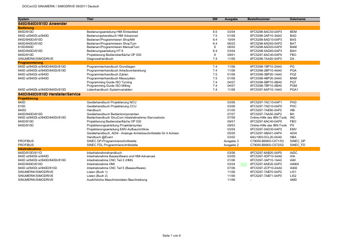
System Titel SW Ausgabe Bestellnummer Dateiname 840D/840Di/810D AnwenderBedienung840D/810D Bedienungsanleitung HMI Embedded 6.503/046FC5298-6AC00-0AP3BEM840D sl/840Di sl/840D Bedienungshandbuch HMI Advanced 7.501/086FC5398-2AP10-3AA0BAD840D/840Di/810D Bedienen/Programmieren ShopMill 6.410/046FC5298-6AD10-0AP3BAS840D/840Di/810D Bedienen/Programmieren ShopTurn 6.406/036FC5298-6AD50-0AP2BAT810D/840D Bedienen/Programmieren ManualTurn608/026FC5298-6AD00-0AP0BAM840D/840Di/810D Bedienungsanleitung HT 6 6.403/046FC5298-0AD60-0AP3BAH840D/810D Projektierung Bedienoberfläche OP 030609/016FC5297-6AC40-0AP0FBO SINUMERIK/SIMODRIVE Diagnosehandbuch7.411/066FC5298-7AA20-0AP3DA Programmierung840D sl/840Di sl/840D/840Di/810D Programmierhandbuch Grundlagen 7.411/066FC5398-1BP10-2AA0PG840D sl/840Di sl/840D/840Di/810D Programmierhandbuch Arbeitsvorbereitung 7.411/066FC5398-2BP10-4AA0PGA840D sl/840Di sl/840D Programmierhandbuch Zyklen 7.501/086FC5398-3BP20-1AA0PGZ840D sl/840Di sl/840D Programmierhandbuch Messzyklen7.501/086FC5398-4BP20-2AA0BNMProgramming Guide ISO Turning7.404/076FC5398-5BP10-0BA0PGTProgramming Guide ISO Milling7.404/076FC5398-7BP10-0BA0PGM840D sl/840Di sl/840D/840Di/810D Listenhandbuch Systemvariablen 7.411/066FC5397-6AP10-1AA0PGA1 840D/840Di/810D Hersteller/ServiceProjektierung840D Gerätehandbuch Projektierung NCU 03/066FC5297-7AC10-0AP1PHD810D Gerätehandbuch Projektierung CCU03/066FC5297-7AD10-0AP0PHC840Di Handbuch01/056FC5297-7AE60-0AP2HBi840D/840Di/810D Gerätehandbuch Bedienkomponenten07/076FC5297-7AA50-0AP2BH840D sl/840Di sl/840D/840Di/810D Bedienhandbuch SinuCom Inbetriebnahme-/Servicetools07/08Online-Hilfe des IBN-Tools INC840D/810D Projektierung Bedienoberfläche OP 03009/016FC5297-6AC40-0AP0FBO840D/810D Projektierungsanleitung Projektiersyntax09/03Online-Hilfe des IBN-Tools PSProjektierungsanleitung EMV-Aufbaurichtlinie03/046FC5297-0AD30-0AP2EMVGerätehandbuch, ADI4 - Analoge Antriebsschnittstelle für 4 Achsen05/056FC5297-0BA01-0AP4ADI4Handbuch @Event03/026AU1900-0CL20-0AA0HBA PROFIBUS SINEC DP-Programmierschnittstelle Ausgabe 3C79000-B8900-C071/03SINEC_DP PROFIBUS SINEC FDL Programmierschnittstelle Ausgabe 2C79000-B8900-C072/02SINEC_FD Inbetriebnahme840D/810D/611D Inbetriebnahmehandbuch03/066FC5297-6AB20-0AP0IADC840D sl/840Di sl/840D Inbetriebnahme Basesoftware und HMI-Advanced03/096FC5397-0DP10-3AA0IHA840D sl/840Di sl/840D/840Di/810D Inbetriebnahme CNC Teil 2 (HMI)01/066FC5397-3AP10-1AA0IAM840D/840Di/810D Inbetriebnahme HMI03/046FC5297-6AE20-0AP3IAM04840D sl/840Di sl/840D/810D Inbetriebnahme CNC Teil 5 (Basesoftware)07/066FC5397-2CP10-2AA0IAM2 SINUMERIK/SIMODRIVE Listen (Buch 1)11/066FC5297-7AB70-0AP2LIS1 SINUMERIK/SIMODRIVE Listen (Buch 2)11/066FC5297-7AB71-0AP0LIS2 SINUMERIK/SIMODRIVE Ausführliche Maschinendaten Beschreibung11/06-AMDFunktionen840D sl/840Di sl/840D/840Di/810D Funktionshandbuch Grundfunktionen11/066FC5397-0BP10-2AA0FB1840D sl/840Di sl/840D/840Di/810D Funktionshandbuch Erweiterungsfunktionen11/066FC5397-1BP10-2AA0FB2840D sl/840Di sl/840D/840Di/810D Funktionshandbuch Sonderfunktionen11/066FC5397-2BP10-2AA0FB3611D/840D/810D Funktionshandbuch Antriebsfunktionen05/106SN1197-0AA80-2AP1FBA840D/840Di/810D Funktionsbeschreibung Werkzeugverwaltung09/056FC5297-6AC60-0AP1FBW802D sl/840D/840D sl/840Di/840Di sl/810D Funktionshandbuch ISO-Dialekte für SINUMERIK03/076FC5297-7BP10-0AA0FBFA840D/611D Funktionshanduch HLA-Modul 03/066SN1197-0AB60-0AP4FBHLA840D/611D Funktionsbeschreibung ANA-MODUL02/006SN1197-0AB80-0AP0FBAN840D/611D Funktionsbeschreibung Safety Integrated03/066FC5297-7AB80-0AP1FBSI840D sl/840Di sl/840D/840Di/810D Funktionsbeschreibung Synchronaktionen11/066FC5397-5BP10-2AA0FBSY840D Funktionsbeschreibung Digitalisieren 07/996FC5297-4AC50-0AP0FBD840D/840Di/810D Funktionsbeschreibung Ferndiagnose03/046FC5297-0AF00-0AP3FBFE840D Funktionsbeschreibung C-PLC-Programmierung03/966FC5297-3AB60-0AP0FBP840D/840Di/810D Funktionsbeschreibung ShopMill 02/056FC5297-6AD80-0AP3FBSP840D/840Di/810D Funktionsbeschreibung ShopTurn03/046FC5297-6AD70-0AP2FBT840D/810D Funktionsbeschreibung ManualTurn08/026FC5297-6AD50-0AP0FBMA840D/810D Funktionsbeschreibung ManualTurn, Ergänzende Informationen07/04-FBMAx802D/802D base lineAnwender802D base line Bedienen und Programmieren, Drehen208/056FC5698-2AA00-1AP4802D_BPD802D Kurzanleitung Drehen111/006FC5698-1AA30-0AP0802DBNKD802D Kurzanleitung ISO-Dialekt Drehen109/016FC5698-1AA60-0AP0802D_ISD802D Bedienen und Programmieren, Fräsen208/056FC5698-2AA10-1AP5802D_BPF802D Kurzanleitung Fräsen111/006FC5298-1AA40-0AP0802DBNKF802D Kurzanleitung ISO-Dialekt Fräsen 109/016FC5698-1AA50-0AP0802D_ISF802D Diagnoseanleitung110/026FC5698-2AA20-0AP1802D_DIA Hersteller/Service802D base line Funktionsbeschreibung11/036FC5697-2AA10-0AP2802D_fb802D base line Inbetriebnahmehandbuch08/056FC5697-2AA00-1AP5802D_IBNGerätehandbuch, ADI4 - Analoge Antriebsschnittstelle für 4 Achsen05/056FC5297-0BA01-0AP4ADI4802S/802C base lineAnwender802S/ 802C base line Bedienen und Programmieren, Drehen408/036FC5598-4AA01-0AP0802SC_BPD 802S/ 802C base line Bedienen und Programmieren, Fräsen408/036FC5598-4AA11-0AP0802SC_BPF802S/ 802C base line Diagnoseanleitung408/036FC5598-4AA21-0AP0802SC_DIA Hersteller/Service802S/802C base line Funktionsbeschreibung08/036FC5597-4AA11-0AP0802SC_FB802C base line Inbetriebnahmeanleitung08/036FC5597-4AA21-0AP0802C_IBN802S base line Inbetriebnahmeanleitung08/036FC5597-4AA01-0AP0802S_IBN SIMODRIVE base line A Start-Up09/046SN1197-0AB21-0BP1802C_IBN_SBLASIMODRIVE611 digital Projektierungshandbuch Umrichter05/086SN1197-0AA00-1AP1PJU611 universal Funktionshandbuch06/116SN1197-0AB20-2AP3FBU611 universal Tausch Ersatzteil07/05A5E00150834FBU_TE611 universal Tausch Ersatzteil HR/HRS12/05A5E00423710FBU_TEH611 analog Inbetriebnahmeanleitung10/006SN1197-0AA60-0AP6IAA611 analog Beschreibung10/006SN1197-0AA30-0AP1BSFunktionsbeschreibung FM-STEPDRIVE/SIMOSTEP02/056SN1197-0AA70-0YP4FBSTSINAMICS S120/SIMODRIVE Systemhandbuch Schaltschrankintegration09/076SL3097-0AT00-0AP0SH1 SIMODRIVE SensorBenutzeranleitung Absolutwertgeber mit PROFIBUS-DP07/056SN1197-0AB10-0YP4BHAProjektierungshandbuch Hohlwellenmesssystem SIMAG H201/116SN1197-0AB31-0AP8PMH2Montageanleitung SIMAG H2 an SIMAG H08/05-SIMAGH2_M1Montageanleitung SIMAG H2 an SIZAG 208/05-SIMAGH2_M2Montageanleitung Zahnradgeber SIZAG 205/086SN1197-0AB00-0YP3SIZAG2_MBetriebsanleitung Gebersysteme ERN 1381.00106/03610.41 334.02ERN1381_BEBetriebsanleitung Gebersysteme ERN 1387 … / S21 / EQN 1325 …01/05610.41 304.02ERN1387_BEBeiblatt Anschlusshaube Hohlwellengeber PROFIBUS DP06/05-SSB_DPHBeiblatt Anschlusshaube Vollwellengeber PROFIBUS DP05/04-SSB_DPVBeiblatt Geberstecker SSI - EnDat06/08-SSB_SSIBeiblatt Geberstecker TTL - HTL- 1Vpp07/04-SSB_TTL Synchronmotoren1FK6Projektierungsanleitung Drehstrom-Servomotoren05/036SN1197-0AD05-0AP0PFK61FK7Projektierungshandbuch Synchromotoren10/056SN1197-0AD06-0AP1PFK71FK7Betriebsanleitung Drehstrom-Servomotoren 1FK7 02. - 1FK7 10. 03/11610.40700.01c1FK7_BE1FK7Betriebsanleitung Getriebemotoren03/05610.40 064.011FK7G_BE1FK7/1FT6Betriebsanleitung Getriebemotoren-Planetengetriebe09/05610.40 072.011FK7GP_BE1FT5Projektierungsanleitung Drehstrom-Servomotoren 05/036SN1197-0AD01-0AP0PFT51FT5Betriebsanleitung Drehstrom-Servomotoren 1FT5 02. -1FT5 04.09/93610.42078.21.a1FT502_BE1FT5Betriebsanleitung Drehstrom-Servomotoren 1FT5 06. -1FT5 13.04/93610.41199.21.c1FT506_BE1FT6Projektierungshandbuch Synchronmotoren 1FT610/056SN1197-0AD02-0AP1PFT61FT6Betriebsanleitung Drehstrom-Servomotoren 1FT6 02. -1FT6 10.07/03610.43 410.211FT602_BE1FT6Betriebsanleitung Drehstrom-Servomotoren 1FT6 13. -1FT6 16.03/07610.43 600.211FT613_BE1FT6Instandhaltungsanleitung Drehstrom-Servomotoren 1FT6 03 - 04 / 06 - 1307/96610.43411.02.a1FT6_IA1FT7Projektierungshandbuch Synchronmotoren 1FT703/106SN1197-0AC13-0AP3PFT71FT7Betriebsanleitung Synchronmotoren 1FT705/11610.40075.01c1FT7_BE1FE1Projektierungshandbuch Synchron-Einbaumotoren09/086SN1197-0AC00-1AP0PFE11FE1Montagehandbuch Synchron-Einbaumotoren10/10610.43000.011FE1_M1FE1Betriebsanleitung Spannungs-Begrenzungs-Modul VPM20008/09A5E00302261B1FE1_VPM200_BE 1FE1Betriebsanleitung Spannungs-Begrenzungs-Modul VPM200 DYNAMIK08/09A5E00777655A1FE1_VPM200D_BE 1FE1Betriebsanleitung Spannungs-Begrenzungs-Modul VPM12008/09A5E00302281B1FE1_VPM120_BE 1PH8Betriebsanleitung Synchron-/Asynchronmotoren 1PH813 und 1PH81605/10610.48006.011PH813_BE1PH8Betriebsanleitung/Montageanleitung Drehstrom-Synchronmotoren 1PH818, 1PH82207/10A5E03029571B AA1PH818S_BE1PH8Betriebsanleitung Drehstrom-Synchronmotoren 1PH818, 1PH82209/09A5E02446774B AB1PH818S_BE0909 2SP1Projektierungshandbuch ECS-Motorspindel11/086SN1197-0AD04-0AP5PMS2SP1Betriebsanleitung ECS-Motorspindel02/116SN1197-0AD14-0AP12SP1_BEAsynchronmotoren1PH2Projektierungsanleitung Asynchronmotoren 10/036SN1197-0AC63-0AP0APH21PH2Betriebsanleitung Drehstrom-Einbaumotoren 04/96610.43 414.021PH2_BE1PH4Projektierungshandbuch Asynchronmotoren04/066SN1197-0AC64-0AP1APH41PH4Betriebsanleitung Asynchronmotoren 1PH405/10610.43093.01e1PH4_BE1PH7Projektierungsanleitung Asynchronmotoren05/046SN1197-0AC65-0AP1APH71PH7Betriebsanleitung Fremdbelüftete Drehstrommotoren 1PH7 10-1611/08610.43 429.211PH7_BE1PH7Betriebsanleitung Drehstrom-Asynchronmotor 1PH71802/08A5E00215737A1PH718_BE 1PH7Betriebsanleitung Drehstrom-Asynchronmotor 1PH72203/08A5E00264361A1PH722_BE 1PH7Betriebsanleitung Drehstrom-Asynchronmotor 1PH72803/08A5E00171047A1PH728_BE 1PH8Betriebsanleitung Asynchronmotoren 1PH808 und 1PH81005/10610.48004.011PH808_BE 1PH8Betriebsanleitung Synchron-/Asynchronmotoren 1PH813 und 1PH81605/10610.48006.011PH813_BE 1PH8Betriebsanleitung Drehstrom-Asynchronmotor 1PH818, 1PH822, 1PH82807/09A5E02605207B AA1PH8_BE1PM6/1PM4Projektierungshandbuch Hohlwellenmotoren08/056SN1197-0AD03-0AP1PPM1PM6Betriebsanleitung Hohlwellenmotoren, luftgekühlt12/05610.40 037.311PM6_BE1PM4Betriebsanleitung Hohlwellenmotoren, flüssigkeitsgekühlt12/05610.40 036.311PM4_BE Linear-/Torquemotoren1FN1Projektierungshandbuch Linearmotoren10/066SN1197-0AB72-0AP0PFN11FN3Projektierungshandbuch Dauerlastmotoren03/086SN1197-0AB74-0AP2PFN3DLM1FN3Projektierungshandbuch Spitzenlastmotoren04/086SN1197-0AB73-0AP1PFN3SLM1FW6Projektierungshandbuch Einbau-Torquemotoren05/096SN1197-0AD00-0AP7PJTM1FW6Betriebsanleitung Einbau-Torquemotoren 1FW606/116SN1197-0AF00-0AP01FW6_BE1FN1/1FN3/1FW6Gerätehandbuch Sensor Module External SME9x11/076SN1197-0AE10-0AP0GH_SME9x Sicherheitshinweise für Direktantriebe01/10-1FN_FW_SH Dezentrale AntriebstechnikPOSMO A Benutzerhandbuch10/076SN2197-0AA00-1AP1POS1 POSMO A Betriebsanleitung Power Management Modul DC-PMM / 24 V04/03-POS1_BE24 POSMO A Betriebsanleitung Power Management Modul DC-PMM / 48 V04/03-POS1_BE48 POSMO A Montageanleitung08/03A5E00158596POS2 POSMO A Montageanleitung "getrennte Variante"12/06A5E00397126Aaf posa_mv POSMO A Montageanleitung Tausch Antriebseinheit 12/01A5E00101611B posa_mta POSMO A/SI Montageanleitung Tausch Getriebe02/04A5E00297127posa_mtg POSMO SI/CD/CA Benutzerhandbuch06/086SN2197-0AA20-1AP4POS3 POSMO SI/CD/CA Montageanleitung Entstörfilter 08/03A5E00245073B-A1poscd_mf POSMO SI/CD/CA Montageanleitung Tausch PROFIBUS–Einheit 07/06A5E00145169 ae poscd_mpe POSMO SI/CD/CA Montage Entstörfilter ECOFAST03/03-poscd_mfe POSMO SI/CD/CA Montageanleitung Tausch PROFIBUS-Einheit ECOFAST07/06A5E00335711 ac poscd_mpee POSMO SI Montageanleitung07/06A5E00282739 ac poss_m POSMO SI Montageanleitung Tausch Lüfter 07/05462 028 0042 00ab poss_mtl POSMO SI Montageanleitung Tausch Antriebseinheit 07/05A5E00145904ac poss_mta POSMO SI Montageanleitung mit PROFIBUS–Einheit ECOFAST07/06A5E00335557 ac poss_mpe POSMO CD/CA Montageanleitung07/06A5E00257954 ad posca_m POSMO CD/CA Montageanleitung mit PROFIBUS–Einheit ECOFAST07/06A5E00335554 ac posca_meMotion Control Information System840D sl/840Di sl/840D/840Di/810D Funktionshandbuch Rechnerkopplung RPC SINUMERIK10/056FC5297-6AD61-0AP1FBR840D sl/840Di sl/840D/840Di/810D Funktionshandbuch NC-Programmmanagement DNC Plant/Cell12/106FC5297-2AE80-0AP3FBDN840D sl/840Di sl/840D/840Di/810D Funktionsbeschreibung NC-Programmmanagement DNC Machine09/036FC5297-1AE81-0AP0FBDM840D sl/840Di sl/840D/840Di/810D Benutzeranleitung Bedienoberfläche "DNC-Machine"07/07-BBDNC 840D sl/840Di sl/840D/840Di/810D Funktionsbeschreibung,Vorbeugende Instandhaltung TPM02/076FC5260-2FX28-0AG3FBTP840D sl/840Di sl/840D/840Di/810D Funktionsbeschreibung TDI Ident Connection06/036FC5297-1AE60-0AP0FBIC840D sl/840Di sl/840D/840Di/810D Bedienungsanleitung Tool Data Information (TDI) 06/076FC5297-6AE01-0AP4BTDI840D sl/840Di sl/840D/840Di/810D Betriebsanleitung ADDM Server Version 6.008/05-BEDMS 840D sl/840Di sl/840D/840Di/810D Betriebsanleitung ADDM Client Version 6.110/07-BEDMC 840D sl/840Di sl/840D/840Di/810D Betriebsanleitung ADDM Agent Version 1.107/05-BEDMA 840D sl/840Di sl/840D/840Di/810D Benutzeranleitung MDA / PDA Maschinenauswertungen08/07-GUIRT 840D sl/840Di sl/840D/840Di/810D Benutzeranleitung MDA Monitor08/07-MonGUI 840D sl/840Di sl/840D/840Di/810D Benutzeranleitung MDA Bedienoberfläche "Projektierung"08/07-PrjGUI840D sl/840Di sl/840D/840Di/810D Benutzeranleitung MDA Werkskalender08/07-WkalGUI 840D sl/840Di sl/840D/840Di/810D Projektierung MDA10/07-PMDA840D sl/840Di sl/840D/840Di/810D Inbetriebnahme MDA Machine10/07-IMDA_M 840D sl/840Di sl/840D/840Di/810D Inbetriebnahme MDA Cell10/07-IMDA_C 840D sl/840Di sl/840D/840Di/810D Inbetriebnahme MDA HMI06/07-IMDA_HMI 840D sl/840Di sl/840D/840Di/810D Inbetriebnahme Datenbankprogramm Oracle für MDA04/05-IMDA_O 840D sl/840Di sl/840D/840Di/810D Funktionsbeschreibung MDA Machine 10/03-FMDA SIMATIC PostionierbaugruppenHandbuch FM 353 für Schrittantrieb08/086ES7353-1AH01-8AG0FM353Handbuch FM 354 für Servoantrieb08/086ES7354-1AH01-8AG0FM354Getting Started Erste Schritte zur Inbetriebnahme FM 354/FM 35304/07-FM354_GSHandbuch FM 357-2 für Servo- bzw. Schrittantrieb01/036ES7357-4AH00-8AG0FM357_2Handbuch FM 453 für Servo- bzw. Schrittantrieb08/086ES7453-3AH00-8AG0FM453Getting Started Erste Schritte zur Inbetriebnahme FM 45304/07-FM453_GS ePS Network Services840D/840Di/810D Installationshandbuch02/08-EPS_IA 840D/840Di/810D Bedienhandbuch11/06-EPS_BH 840D sl/840Di sl/840D/840Di Projektierungshandbuch04/10-EPS_PH 840D sl/840Di sl/840D/840Di Funktionshandbuch12/10-EPS_FH 840D sl/840D Betriebsanleitung eP-Satellite Server12/10-EP_BA 840D/840Di/810D Leistungsbeschreibung ASP Schein01/09-EPS_LB 840D sl/840Di sl/840D/840Di Release Notes12/10-EPS_RNSIMATICSIMATIC S7Getting Started: Erste Schritte und Übungen mit STEP 7 V5.403/06-S7_GS SIMATIC S7Programmieren mit STEP 7 V5.403/06-S7P SIMATIC S7HW konfigurieren und Verbindungen projektieren mit STEP 7 V5.403/06-S7_HW SIMATIC S7-300/400Referenzhandbuch Kontaktplan (KOP)03/06-S7_KOP SIMATIC S7-300/400Referenzhandbuch Funktionsplan (FUP)03/06-S7_FUP SIMATIC S7-300/400Referenzhandbuch Anweisungsliste (AWL)03/06-S7_AWL SIMATIC S7-300/400Referenzhandbuch System- und Standardfunktionen03/06-S7_SFC SIMATIC S7-300Betriebsanleitung CPU 31xC und CPU 31x: Aufbauen06/08-S7_BA31A SIMATIC S7-300Gerätehandbuch CPU 31xC und CPU 31x, Technische Daten06/08-S7_GH31TD SIMATIC S7-300Referenzhandbuch CPU-Daten CPUs 312 IFM bis 318-2 DP10.01-S7300Re2 SIMATIC S7-300Operationsliste CPU Daten: CPUs 312 IFM bis 318-2 DP10.01-S7OP1 SIMATIC S7-300Operationsliste CPU 31xC, CPU 31x06/08-S7OP2 SIMATIC S7-300Technologische Funktionen: CPU 31xC02/07-S7300TF SIMATIC S7-200Systemhandbuch09/07-S7200SH SIMATIC S7-200Systemhandbuch CPU 210Ausgabe 1-S7_C210 SIMATIC Systemhandbuch Kommunikation mit SIMATIC09/06-SSH_Komm SIMATIC HMI Betriebsanleitung Bediengerät Mobile Panel 177 (WinCC flexible)07/05-SBE_MP177 Info/TrainingSystemhandbuch Safety Integrated20056ZB5000-0AA02-0BA1APPL_HBSystemhandbuch Safety Integrated Nachtrag20066ZB5000-0AB01-0BA0APPL_HBNTrainingsunterlage Einfacher fräsen mit ShopMill08/066FC5095-0AA50-0AP2TUSMTrainingsunterlage Einfacher drehen mit ShopTurn04/046FC5095-0AA80-0AP1ST_ein840D/840Di/810D Einsteigeranleitung Fräsen und Drehen 10/036FC5095-0AB00-0AP1SIN_ein840D/840D sl/840Di Handbuch 5 Achs-Bearbeitung05/096FC5095-0AB10-0AP1SIN_WF5 840D/840Di/810D/802D sl Handbuch Werkzeug- und Formenbau (3 Achsen)08/076FC5095-0AB20-0AP0SIN_WF3 SteuerungsübersichtSINUMERIK powerline Funktionsübersichten 2009-BU840D/810D Steuerungsübersicht Fräsen mit ShopMill06/07-SSM840D/810D Steuerungsübersicht Drehen mit ShopTurn04/07-SSTaktualisierte Ausgabeerstmalig auf DOConCD。

生产线的装置和运行流程英文回答:Production Line Setup and Operation.The setup and operation of a production line involves several key steps to ensure efficient and reliable manufacturing processes. Here's an overview of the typical setup and operation flow:1. Design and Planning:Determine the product specifications, production volume, and desired cycle time.Design the production layout, including workstation arrangement, material flow, and equipment selection.2. Equipment Acquisition and Installation:Procure and install the necessary machines, conveyors, and other equipment based on the production design.Calibrate and test the equipment to ensure accuracy, speed, and reliability.3. Material Procurement and Storage:Establish material handling systems to procure and store raw materials, components, and finished goods.Implement inventory management techniques to maintain optimal material levels.4. Workforce Training and Development:Train operators on machine operation, safety procedures, and quality control standards.Provide ongoing training to enhance skills and keep up with technological advancements.5. Process Optimization:Implement continuous improvement practices to optimize production processes.Monitor performance metrics, identify bottlenecks, and implement solutions to improve efficiency.6. Quality Control:Establish quality control measures throughout the production line to ensure product quality and compliance with standards.Conduct regular inspections, tests, and audits to maintain high-quality output.7. Maintenance and Repair:Establish a preventive maintenance schedule to regularly service and repair equipment.Train maintenance personnel on troubleshooting techniques to minimize downtime.8. Monitoring and Control:Implement monitoring systems to track production progress, identify potential issues, and make timely adjustments.Collect data for analysis and use in decision-making processes.中文回答:生产线的装置和运行流程。