XY-Q200换相开关说明书
- 格式:pdf
- 大小:1.13 MB
- 文档页数:20


WiringConnectionConnections should only be made with the power supply turned off.may result due to noise.using a commercially available switch-mode powersupply. When a switch-mode power supply is connected to the product,switching noise will be superimposed and the product specification can nolonger be met. This can be prevented by inserting a noise filter, such as aline noise filter and ferrite core, between the switch-mode power supply andthe product, or by using a series power supply instead of the switch-modepower supply.Set ON and OFF point of the Pressure switch.Operation (Hysteresis mode)When the pressure exceeds the set value, thePressure switch will turn ON.When the pressure falls below the setvalue by the amount of hysteresis ormore, the Pressure switch will turn OFF.The default setting of the output set valueis the central value between theatmospheric pressure and theupper limit of the rated pressurerange. If this condition, shown to the right,is acceptable, then keep these settings.Pressure SettingDigital Pressure SwitchOperation ManualZSE80(F)/ISE80(H)Thank you for purchasing an SMC ZSE80(F)/ISE80(H) Series Digital PressureSwitch.Please read this manual carefully before operating the product and make sure youunderstand its capabilities and limitations.Please keep this manual handy for future reference.To obtain more detailed information about operating this product, pleaserefer to the SMC website (URL ) or contact SMCdirectly.These safety instructions are intended to prevent hazardous situations and/orequipment damage.These instructions indicate the level of potential hazard with the labels of"Caution", "Warning" or "Danger". They are all important notes for safety and mustbe followed in addition to International standards (ISO/IEC) and other safetyregulations.LCD display: Displays the current status of pressure, setting mode, selectedindication unit and error code.Four display modes can be selected: display always in red orgreen, or display changing from green to red, or red to green,according to the output status.button (UP): Selects the mode or increases ON/OFF set value.Press this button to change to the peak display mode.button (DOWN): Selects the mode or decreases ON/OFF set value.Press this button to change to the bottom display mode.button (SET): Press this button to change to another mode and to set a value.InstallationMountingMount the optional bracket and panel mount adapter to the Pressure switch.When the Pressure switch is to be mounted in a place where water and dustsplashes occur, insert a tube (O.D ø4, I.D ø2.5) into the air-relieving port ofthe Pressure switch.OperatorSafety InstructionsNOTE•The direct current power supply to be used should be UL approved as follows:Circuit (of Class2) which is of maximum 30 Vrms (42.4 V peak), with UL1310Class2 power supply unit or UL1585 Class2 transformer.•The product is a approved product only if it has a mark on the body.Other SettingsPeak / Bottom hold displayZero clearKey lockTo set each of these functions, refer to the SMC website(URL ) for more detailed information, or contact SMC.MaintenanceHow to reset the product after a power cut or forcible de-energizingThe setting of the product will be retained as it was before a power cut orde-energizing.The output condition is also basically recovered to that before a power cut orde-energizing, but may change depending on the operating environment.Therefore, check the safety of the whole installation before operating the product. Ifthe installation is using accurate control, wait until the product has warmed up(approximately 10 to 15 minutes).TroubleshootingError IndicationSpecificationsOutline with Dimensions (in mm)contact SMC.Note: Specifications are subject to change without prior notice and any obligation on the part of the manufacturer.© 2011 SMC Corporation All Rights ReservedAkihabara UDX 15F, 4-14-1, Sotokanda, Chiyoda-ku, Tokyo 101-0021, JAPANPhone: +81 3-5207-8249 Fax: +81 3-5298-5362URL Mounting with bracketFix the bracket to the Pressure switch with the set screws M3 x 5 L (2 pcs.) supplied.Apply a tightening torque of 0.98 Nm or less.•Rear piping ...Bracket A (Model: ZS-24-A)Bracket D (Model: ZS-24-D)•Bottom piping ...Bracket B (Model: ZS-35-A)<Rear piping><Bottom piping>Measurement modeThe measurement mode is the condition wherethe pressure is detected and indicated, and theswitch function is operating.This is the basic mode, and the other modesshould be selected for setting changes and otherfunction settings.2. [P_1] or [n_1] and set value aredisplayed in turn.∗: The Pressure switch will also output during setting.button once in measurement mode.Displays in turnSwitch ONAt normal outputSwitch OFFSet valueP_1Time [s]Pressure[Pa]HysteresisH_1button once to increase by oneincreasing the set value.button once to decrease by onedecreasing the set value.The Pressure switch operates within a set pressure range (from P1L to P1H)during window comparator mode. Set P1L (switch lower limit) and P1H (switchupper limit) with the setting procedure above. (When reversed output isselected, [n1L] and [n1H] are displayed.)button to complete the setting.∗button is pressed for 2 seconds or longer, the setting is fixed and measurementFunction SettingFunction selection modebutton[F button for 2 seconds orto measurement mode.∗: Some functions are not available depending on partnumber. All functions are displayed with [F] followed by the function description. If a functionis not available, the function is displayed as [---].Default settingAt the time of shipment, the following settings are provided.If the setting is acceptable, keep it for use.Refer to the SMC website (URL ) for more detailedinformation about setting changes, or contact SMC.[F 0] Unit conversion functionMeasurement modeFunction selection modePress the button for2 s or longer.[F 1] Setting of OUT1[F 2] Setting of OUT2Same setting as [F 1] OUT1.The display colour is linked to the setting of OUT1, and can not be set forOUT2.Refer to the product catalogue or SMC website (URL ) formore information about the product specifications and outline dimensions.Mounting with panel mount adapter•Panel mount adapter (Panel mount adapter A, B and mounting bracket included)Rear piping ...Model: ZS-35-CBottom piping ...Model: ZS-35-B•Panel mount adapter + Front protective coverRear piping ...Model: ZS-35-FBottom piping ...Model: ZS-35-E<Rear piping><Bottom piping>PipingConnection using screw type fittingConnect suitable piping to the port.To connect the hexagon socket head plug or fitting tothe pressure port, hold the hexagon part of thepressure port with a suitable spanner. Apply atightening torque of 13.6 Nm or less.Spanner(17 mm)Tube attachmentWhen the Pressure switch is used in a place where water and dust splashesmay occur, insert a tube into the air-relieving port and route the other end ofthe tube to a safe place away from water and dust. (See the figure below)<Rear piping><Bottom piping>Air-relieving port∗: SMC TU0425 (polyurethane, O.D ø4, I.D ø2.5) is a suitable tubing.Refer to the product catalogue or SMC website (URL )for more information about panel cut-out and mounting hole dimensions.Refer to the SMC website (URL ) for more informationabout troubleshooting.。

一、用途QBZ系列矿用隔爆型真空电磁起动器适用于具有爆炸性危险气体和煤尘的煤矿井下,在交流50Hz、电压至660V 或1140V的电力系统中,作为就地或远距离控制额定电流分别至80A、120A、200A的矿用隔爆型三相鼠笼式异步电动机的起动或停止之用。
并可在被控电动机停止时进行换向,同时对电动机及有关电路进行过载、短路、断相、主电路漏电闭锁和失压保护。
起动器特别适用于频繁操作、重负荷的煤矿机械设备控制。
二、技术参数型号QBZ-80 QBZ-120 QBZ-200 QBZ-80/1140 额定工作电压380V,660V额定工作电流80A 120A 200A 80Aη.cosφ=0.75时控制电机的最大功率380V 40Kw 60Kw 100Kw 115Kw 660V 65Kw 100Kw 170Kw 115Kw控制回路电压36V额定工作电流1600A(3次) 2500A(3次) 4500A(3次) 1600A(3次) 引入电缆外径主回路φ32~40mm φ32~40mm φ42~51mm φ32~40mm控制回路φ12~19mm型号QBZ-80N QBZ-120N QBZ-200N 额定工作电压380V 660V 380V 660V 380V 660V额定工作电流80A 120A 200A矿用隔爆型交流真空软起动器QBZ--200/660(380)一、型号及其含义QBZ □/ □额定工作电压V额定工作电流A矿用隔爆型真空软起动器二用途QBZ系列矿用隔爆型交流真空软起动器,适用于含有甲烷混合气体,具有爆炸危险煤矿井下。
在额定电压至1140V以下,在额定频率50HZ,额定电流400A以下的三相异步电动机的软起动、软停车,可以就地或远距离和联机起动控制的三相异步电动机。
三主要功能本公司生产的系列软起动器采用进口大功率电力电子元件、微处理器技术与现代控制理论设计,适用于煤矿井下重载难起动、常速运行设备电动机的控制,与国内目前大量使用的传统控制方式相比具有以下显著特点:1、消除机械动载冲击,延长电机及相关设备使用寿命;2、电机起动电流小,减小电网冲击,降低电网配电容量;3、独有调频调速控制功能,提升起动力矩,实现重载起动;4、负载自动跟踪技术,双机运行可实现功率平衡;5、控制系统采用微处理器、模糊控制及大电流过零分断技术,具有强的负载适应与电磁兼容能力,性能稳定可靠;6、全数字化控制系统,根据用户需求进行参数配置;7、设有通讯接口,方便实现自动控制;8、具有多种起动模式及保护功能。

QJZ2-2000/1140(660)系列矿用隔爆型兼本质安全型组合开关使用说明书八达电气有限公司QJZ2-2000/1140(660)系列矿用隔爆兼本质安全型组合开关使用说明书1、概述1.1用途及适用范围QJZ2-2000/1140(660)系列矿用隔爆兼本质安全型组合开关(以下简称组合开关)适用于含有爆炸性危险气体和煤尘的矿井中,在交流50Hz、额定电压1140V(660)的线路中,对三相鼠笼型异步电动机的起动、停止进行控制和保护,并可在停止时改变相序。
1.2 型号及意义1.2.1组合开关的型号及其代号含义如下:Q J Z 2—主回路数额定电压(V)总电流(A),按用户需要组合各回路电流真空式隔爆兼本质安全型起动器1.2.2防爆形式和防爆标志防爆形式: 矿用隔爆兼本质安全型防爆标志: Exd(ib)I1.3 使用环境条件1.3.1海拔不超过2000m;1.3.2运行环境温度为-5℃~+40℃;1.3.3周围空气相对湿度不大于95%(+25℃时);1.3.4在有煤尘和爆炸性气体混合物的矿井中;1.3.5与垂直面的安装倾斜度不超过15°;11.3.6在无显著振动和冲击的地方;1.3.7在无破坏绝缘的气体和蒸汽的环境中;1.3.8无滴水的地方;1.3.9污染等级:3级;1.3.10安装类别:Ⅲ类。
1.4用途与特点1.4.1组合开关从4路直到12路组合共用一套PLC控制器和数据采集处理器,使得控制、保护、显示设置相对简单化。
1.4.2主回路的真空接触器、电流互感器、阻容保护装置及二次回路的电流变送器、中间继电器等保护元件,均装在设有滚轮的抽屉小车上,主回路和二次回路都为接插式,方便用户检修与更换。
1.4.3各主回路装设的限流熔断器FU与PLC,对各主回路短路故障进行双重保护,增加了对短路保护的可靠性。
1.4.4组合开关的电缆引入方式,可选用进出线腔压盘式连接,也可选用主回路及控制回路电缆连接器方式连接。
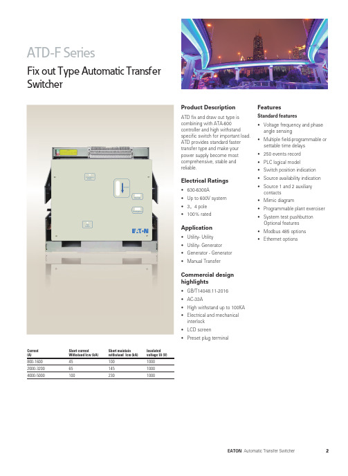
Product DescriptionATD fix and draw out type is combining with ATA-600 controller and high withstand specific switch for important load. ATD provides standard faster transfer type and make your power supply become most comprehensive, stable and reliable.Electrical Ratings• 630-6300A• Up to 600V system• 3,4 pole• 100% ratedApplication• Utility- Utility• Utility- Generator• Generator - Generator• Manual Transfer Commercial design highlights• GB/T14048.11-2016• AC-33A• High withstand up to 100KA• Electrical and mechanicalinterlock• LCD screen• Preset plug terminal FeaturesStandard features• Voltage frequency and phase angle sensing• Multiple field-programmable or settable time delays• 250 events record• PLC logical model• Switch position indication• Source availability indication• Source 1 and 2 auxiliarycontacts• Mimic diagram• Programmable plant exerciser• System test pushbuttonOptional features• Modbus 485 options• Ethernet optionsFix out Type Automatic TransferSwitcherCurrent (A)Short currentWithstand Icw (kA)Short maintainwithstand Icm (kA)Insulatedvoltage Ui (V)800-1600 2000-3200 4000-50004565100100145230100010001000Current (A)Short currentWithstand Icw (kA)Short maintain withstand Icm (kA)Insulated voltage Ui (V)800-16002000-32004000-50004565100100145230100010001000Draw out Type Automatic TransferSwitcherProduct DescriptionATD fix and draw out type is combining with ATA-600 controller and high withstandspecific switch for important load. ATD provides standard faster transfer type and make your power supply become most comprehensive, stable and reliable.Electrical Ratings• 630-6300A • Up to 600V system • 3,4 pole • 100% ratedApplication• Utility- Utility • Utility- Generator • Generator - Generator • Manual TransferCommercial design highlights• GB/T14048.11-2016• AC-33A• High withstand up to 100KA • Electrical and mechanical interlock • LCD screen • Preset plug terminalFeaturesStandard features• Voltage frequency and phase angle sensing • Multiple field-programmable or settable time delays • 250 events record • PLC logical model • Switch position indication • Source availability indication • Source 1 and 2 auxiliary contacts • Mimic diagram• Programmable plant exerciser • System test pushbutton Optional features • Modbus 485 options • Ethernet optionsATD8 SeriesDelay Type Automatic TransferSwitcherProduct DescriptionATD delay type is combining withATA-800 controller and highwithstand specific draw outswitch for important load. ATDdelay type provides a programma-ble delay time in transfer processwhich is required in transfer highrate generator and transformer.On the other hand, delay typetransfer are required in transferUPS or generator to reduce theimpact in the transfer process.Electrical Ratings• 630-6300A• Up to 600V system• 3,4 pole• 100% ratedApplication• Utility- Utility• Utility- Generator• Generator - Generator• Manual TransferCommercial designhighlights• GB/T14048.11-2016• AC-33A• High withstand up to 100KA• Electrical and mechanicalinterlock• LCD screen• Preset plug terminalFeaturesStandard features• Voltage frequency and phaseangle sensing• Multiple field-programmable orsettable time delays• 250 events record• PLC logical model• Switch position indication• Source availability indication• Source 1 and 2 auxiliarycontacts• Mimic diagram• Programmable plant exerciser• System test pushbuttonOptional features• Modbus 485 options• Ethernet optionsCurrent(A)Short currentWithstand Icw (kA)Short maintainwithstand Icm (kA)Insulatedvoltage Ui (V)800-16002000-32004000-50004565100100145230100010001000ATD SeriesFix Demission800-2000A Demission2500-3200A Demission535(4P)420(3P)473NormalEmergencyLocd4784-419.5(3P)(4P)t4-Fix holeFix holeFix holeFix holeFix holeNormalEmergencyLocdATD SeriesFix Demission4000-5000A Demission3P4PNormalEmergencyLocdATD SeriesDraw Demission800-2000A Demission2500-3200A Demission464(4P)349(3P)464(4P)349(3P)(4P)t349(3P)(4P)4-Fix holeFix hole Fix holeFix holeFix holeNormalEmergencyLocdNormalEmergencyLocdATD SeriesDraw Demission4000-6300A Demission3P4PNormalLocdEmergencyProduct guideATD SeriesDemission & Product guideController terminalsDemissionATA 610ATA610 ONLY。
中国驰名商标QJZ系列多回路组合开关使用说明手册QJZ-4×400/1140(660) □QJZ-1600/1140(660)-6 □QJZ-1600/1140(660)-8 □QJZ-2000/1140(660)-9 □QJZ-2000/1140(660)-10 □QJZ-2000/1140(660)-11 □QJZ-2000/1140(660)-12 □中国●电光防爆电气有限公司前言欢迎使用QJZ系列矿用隔爆兼本质安全型组合开关。
本说明书介绍了1140V(660)组合开关的特点和性能,以及应用范围等内容。
组合开关的操作务必在获得了用户主管部门的授权和仔细阅读了本说明书及《使用手册》后方可进行。
本起动器所用保护装置的一些重要操作,如定值修改等,平均设有授权密码,请用户注意,如不按本说明书及使用的要求进行操作,则有可能造成不良后果。
对本说明书如有疑问或有本说明书未涵盖的技术问题,请向厂家咨询。
警告:用户在使用时必须按说明书及使用手册的要求操作严禁带电开盖,严禁损伤防爆面!注意事项★★★★安装使用前,完整阅读使用手册。
★★★★禁止随意插拔光纤线插头,保持光纤线插头、座整洁。
★★★★禁止随意停止所设定的逻辑功能,如需停止只有在所设定的逻辑功能完全启动后才能停止。
★★★★如无特殊情况,请勿带载操作隔离手柄。
★★★★与负载连接时注意相序,避免由于相序错误造成事故。
★★★★首次使用该设备时,断开主回路隔离换向开关用控制回路进行人员培训、和熟悉该设备。
用途此设备只能根据“工作环境”章节的应用说明才能使用。
任何不遵从以上说明的使用都被看作非正确的。
我们声明对非正确使用设备而造成的任何损害不承担任何责任。
特别指出,正确的使用是指遵从所有的操作指导。
在一定期限内要做所有规定的测试和维护工作。
保证和责任对于由以下原因而造成的人身和财产损失,我们不承诺任何保证和承担任何责任。
※没被授权使用※不正确的安装、使用、操作、维护※未经允许擅自改变设备结构※非厂家进行的结构改变※不遵从技术信息※没有经过厂家授权非正确使用及维修备件或附件※不可抗拒力影响※没有完全遵照“安全操作”说明使用※在对设备进行操作时必须遵从使用手册。
天津天高电气有限公司Tianjin Tengoal Electric CO.,LTD.电话:(TEL)022-******** 022-********传真:(FAX)022-******** 022-********邮箱:(E-Mail)*************网址: Http// 邮编:(PC)300240地址:(ADD)天津市东丽区大毕庄工业区Dabizhuang Industry Zone Dongli district Tianjin天 津 天 高 电 气 有 限 公 司Tianjin Tengoal Electric co.,LTD.自动转换开关TBQ使书(路转器 TBQ1/TQB2)1. 概述 .....................................................................01 1.1 产品简介 .........................................................01 1.2 产品型号说明 ...................................................01 1.3 产品主要特点 ...................................................022. 开箱验收注意事项 ...................................................02 3. 常规特性及功能 ......................................................03 3.1 常规特性 .........................................................03 3.2 电气性能及功能 ................................................03 4. 安装使用 ...............................................................05 4.1 介电测试 .........................................................05 4.2 外型及安装尺寸 ................................................05 4.3 用户接线 .........................................................08 4.4 控制器设置及操作 .............................................095. 维护及故障排除 ......................................................12 5.1 维护 ...............................................................12 5.2 常见故障及排除 ................................................12 5.3 售后服务 .........................................................126. 电源自动转换开关次回路用户接线图 ...........................13 6.1 次回路接线图 (13)011、概述1.1 产品简介TBQ系列自动转换开关是我公司利用微机技术研发的新一代路转器自动转换开关。
Vibrating Switches SITRANS LVL200EKONTAKTLOSER SCHALTER操作说明书 • 11/20162*7ML19985KV31*SITRANS LVL200E - 操作说明书33839-ZH-1612053*7ML19985KV31*SITRANS LVL200E - 操作说明书33839-Z H -161205目录1 关于本文献资料1.1 功能 .............................................................................................................................................................................41.2 对象 .............................................................................................................................................................................41.3 使用的标记.................................................................................................................................................................42 为了您的安全2.1 获得授权的人员.........................................................................................................................................................52.2 合规使用 .....................................................................................................................................................................52.3 谨防错误使用.............................................................................................................................................................52.4 一般安全提示.............................................................................................................................................................52.5 仪表上的安全标记 ....................................................................................................................................................52.6 欧盟一致性.................................................................................................................................................................52.7 SIL认证........................................................................................................................................................................52.8 用于防爆区域的安全提示 ........................................................................................................................................53 产品说明3.1 结构 .............................................................................................................................................................................63.2 作业方式 .....................................................................................................................................................................63.3 操作 .............................................................................................................................................................................73.4 仓储和运输.................................................................................................................................................................73.5 配件 .............................................................................................................................................................................84 安装4.1 一般提示 .....................................................................................................................................................................94.2 安装提示 ...................................................................................................................................................................115 与供电装置相连接5.1 准备接线 ...................................................................................................................................................................135.2 接线步骤 ...................................................................................................................................................................135.3 单腔式外壳的接线图 ..............................................................................................................................................146 投入使用6.1 一般性说明...............................................................................................................................................................166.2 调整元件 ...................................................................................................................................................................166.3 功能表 .......................................................................................................................................................................177 仪表维修和故障排除7.1 维护 ...........................................................................................................................................................................187.2 排除故障 ...................................................................................................................................................................187.3 更换电子部件...........................................................................................................................................................187.4 需要维修时的步骤 ..................................................................................................................................................198 拆卸8.1 拆卸步骤 ...................................................................................................................................................................208.2废物清除 ...................................................................................................................................................................209 附件9.1 技术数据 ...................................................................................................................................................................219.2 尺寸 ...........................................................................................................................................................................279.3 商标 ...........................................................................................................................................................................30用于防爆区域的安全提示请在将仪表用于防爆应用领域时遵守专门针对防爆的安全说明。
XY-Q200系列智能换相开关技术使用说明书(V1.06)广西星宇智能电气有限公司GUANGXI XINGYU SMART ELECTRIC CO.,LTD目录第一篇行业背景 (1)1.1 三相不平衡的概念 (1)1.2 三相不平衡的危害 (1)1.3 治理三相不平衡的传统方法 (2)第二篇产品简介 (3)2.1 系统概述 (3)2.2 系统组成 (3)2.3 系统功能 (3)2.4 系统优势 (4)2.5 技术参数 (4)第三篇技术原理 (6)3.1 平衡原理 (6)3.2 不掉电换相原理 (7)第四篇使用说明 (8)4.1 XY-Q210主控开关使用说明 (8)4.2 XY-Q220换相开关使用说明 (10)4.3 手机APP软件 (12)第五篇工程设计说明 (13)5.1 结构与安装方式 (13)5.2 安装方案 (16)5.3 CT技术要求 (16)5.4 系统安装接线图 (16)第一篇行业背景1.1 三相不平衡的概念图1-1 三相负荷分时曲线图1)定义三相不平衡是指在电力系统中三相电流(或电压)幅值不一致,且幅值差超过规定范围。
造成三相不平衡的主要原因是三相负荷不均衡,属于基波负荷配置问题。
2)计算方法和规定《国家电网公司企业标准(Q/GDW519-2010)配电网运行规程》中第8.7.4条规定:不平衡度计算式:(最大电流–最小电流)÷最大电流×100%国网标准:三相负荷不平衡度不应大于15%,只带少量单相负荷的三相变压器,中性线电流不应超过额定电流的25%。
1.2 三相不平衡的危害三相负载不平衡问题对电力系统、用户供电等都带来了严重的危害。
主要表现在以下几个方面:增加变压器损耗增加线路损耗配变出力减小,降低了配变利用率变压器发热,严重时甚至会烧毁变压器容易导致过压、低压,影响用电设备的正常工作我国的低压配电网点多面广、结构复杂,并且随着人们生活水平的不断提高,负荷性质日趋多样化、负荷波动越发显著,使低压台区变三相不平衡问题越发突出。
而另一方面,治理三相不平衡的方法相对欠缺,很难从人力和技术上解决,导致三相负荷不平衡问题非常普遍,尤以农网最为严重。
1.3 治理三相不平衡的传统方法通过人工改线调整负荷这种方法使用率最高,但其人力投入大,需切断用户供电,而且难以长期适应负荷的变化规律。
通过SVG静止同步补偿器补偿SVG静止同步补偿器可以对三相不平衡进行补偿,但这种方法成本高,只能做到变压器低压侧三相电流近似平衡,不是从本质上实现负荷平衡。
通过APF有源滤波器补偿APF有源滤波器除滤除谐波功能外,可对三相不平衡起到一定的补偿作用,但用这种方法成本高昂,同样不是从本质上实现负荷平衡。
综上:传统手段相对欠缺,而且投入大、效率低,不能从根本上解决三相不平衡问题。
第二篇产品简介2.1 系统概述XY-Q200系列智能换相开关是广西星宇智能电气有限公司研发的一套用于治理三相不平衡的产品。
它适用于三相四线制的380V/220V低压配电系统,能够在不中断用户供电的情况下根据不平衡度自动调节三相负载,克服传统依靠人工改线来调节三相不平衡的缺点。
本产品可有效降低由三相负载不平衡所导致的变压器损耗、线路损耗,克服某相过流、末端低压等情况,以及由三相不平衡带来的众多安全隐患。
2.2 系统组成XY-Q200系列智能换相开关包括XY-Q210主控开关和XY-Q220换相开关:XY-Q210主控开关是是集采样、运算、通信、人机交互、智能组网、平衡逻辑算法于一体的智能控制装置。
XY-Q220换相开关是集采样、运算、通信、相序切换功能于一体的智能投切装置。
图2-1 XY-Q210主控开关图2-2 XY-Q220换相开关2.3 系统功能自动平衡三相负载实时监测三相不平衡度,并根据不平衡度自动调节三相负载,换相时间≤20ms,不中断用户供电,不会引起常用电器的复位和重启动,也不会对电器产生损害。
降低变压器损耗使变压器处于对称运行状态,有效降低了变压器损耗。
降低线路损耗有效减小中性线电流,从而减小中性线的损耗及相线的损耗。
解决低压、过压问题解决由三相不平衡所导致的低压、过压的问题,避免因过压烧坏用电设备或因低压影响用电设备的正常运行。
保护低压配网安全运行避免中性线电流长期过大导致的发热和老损,避免变压器等配电设备烧毁的隐患。
2.4 系统优势免维护、免管理系统投运后无需专人维护和管理,节省人力物力,提高效率自动换相,不需中断用户供电1)自动换相,无需人工参与2)换相时间≤20ms,不会导致供电中断可靠的相间防短路技术1)可靠的硬件闭锁技术,防止多个相序同时接通2)多重软件算法,智能预防相间短路开关元件不耗电,装置功耗小1)采用永磁继电器机构,无压运行2)装置运行功耗≤8W2.5 技术参数表2-1 产品技术参数分类参数名称换相开关主控开关电气参数接线方式三相四线制三相四线制额定电压AC380V/220V AC380V/220V 额定电流90A/120A --额定频率50Hz 50Hz额定绝缘电阻>100MΩ>100MΩ额定工频耐受电压 2.5kV 2.5kV额定冲击耐受电压5kV 5kV载波通信频率421kHZ 421kHZ性能指标换相时间≤20ms --机械寿命10万次--电流/电压采样精度0.5级0.5级稳定通信距离≤1500米≤1500米防护等级IP54 IP54 SOE存储容量128条128条录波存储容量-- 64M使用环境使用工况户外户外环境温度-10℃ ~ 55℃-10℃ ~ 55℃海拔≤3000m ≤3000m第三篇技术原理3.1 平衡原理1)原理概述图3-1 系统拓扑图每个支路的始端均安装一台主控开关,负责监测三相不平衡信息,并下发调节命令;支路沿线在用户前端安装换相开关,可监测自身带载回路的负荷信息,并根据主控开关下发的换相命令进行相应换相操作。
2)智能组网XY-Q200系列智能换相开关采用电力载波的方式进行通信,每个主控开关只负责与其同支路的换相开关进行通信,一个支路构成一个子系统,主控开关作为主机,换相开关作为从机。
本系统针对多主控开关共网的模式,开发了独特的智能组网机制——抢占式分时通信机制,该机制避免了不同支路之间的载波通信的冲突和干扰,实现了智能组网功能。
3)算法原理基于数学递归逻辑的平衡算法原理当主控开关监测到自身支路的不平衡度超过设定值时,就会启动平衡逻辑算法。
每个用户的用电负荷都不一样,每个支路的不平衡度也不尽相同,本系统基于数学递归逻辑算法的原理,结合调平衡需求和各换相开关的负载大小,进行逻辑组合运算,求解出最优策略。
基于支路平衡策略的平衡算法原理每个支路中的主控开关运算出最优策略后,会命令该支路中的换相开关进行相应的换相操作,从而实现本支路平衡。
台区内每个分支都达到三相平衡状态,即可实现变压器三相平衡。
3.2 不掉电换相原理不掉电换相的实质就是在极短的时间内完成相序的切换,实现基础如下:1)动作元件XY-Q220换相开关,采用永磁继电器作为动作元件。
永磁继电器具有带载能力强、功耗小、动过速度快、损耗小、运行可靠、成本低等特点。
基于永磁继电器的特性,换相开关实现了不掉电换相的功能,换相过程中不会导致用户供电的中断,保证了供电质量。
通过大量的理论调研和实测验证,30ms的掉电时间不会导致用电设备掉电,而XY-Q220换相开关换相时间≤20ms,完全满足应用需求。
2)过零换相为保证寿命,换相开关采用过零投切技术,以将投切对动作元件的损伤降到最小。
过零投切技术基于“电流过零切除,电压过零投入”的原则,可以达到冲击极小、电弧极小的效果。
第四篇 使用说明4.1 XY-Q210主控开关1)端子定义图4-1 XY-Q210主控开关 表4-1 XY-Q210主控开关端子定义编号 定义 功能描述电流端子1 I A A 相电流互感器输入 额定输入电流5A2 I A ’ A 相电流互感器输出 3I B B 相电流互感器输入4 I B ’ B 相电流互感器输出5 I C C 相电流互感器输入6 I C ’ C 相电流互感器输出 7-12/备用电压端子13 FG 机壳地14-23 / 备用24 U A A相电压额定输入电压AC220V25 / 备用26 U B B相电压27 / 备用28 U C C相电压29 / 备用30 U N零线(N相)2)参数设置说明CT变比设置主菜单>参数设置>变比设置,输入变比参数。
时间设置主菜单>参数设置>时间设置,通过‘♦’、‘◆’选择修改的项目,通过‘☐’、‘❑’修改数据。
地址设置每台换相开关都拥有唯一的逻辑地址,地址码标签粘贴于换相开关外壳上,一个系统中每台换相开关的地址均需要输入到主控开关。
设置方法有以下两种:通过手机APP设置:通过配套的手机APP扫描换相开关上的地址标签条形码,将地址数据录入手机内。
然后手机通过WiFi与主控开关连接,将地址数据传输至主控开关内。
手动设置:主菜单>参数设置>通信设置,按‘❑’键添加地址,输入地址号,然后按‘确认’键,输入密码88完成设置。
3)操作密码操作密码出厂默认值为88。
4)按键功能按键名称功能取消返回上一级菜单或进入装置正常运行状态确认进入下一级菜单或确认操作‘☐’、‘❑’移动光标,修改数据‘♦’、‘◆’移动光标,页面切换5)信号指示灯名称颜色说明运行绿色装置正常运行时闪烁,每秒一次告警红色主控开关故障或者检测到故障时,手动清除6)菜单操作液晶显示器采用160×160点阵式背光液晶显示屏。
装置上电后将进行自检,最后进入初始化界面。
在初始化界面状态下,按‘☐’、‘❑’、‘♦’、‘◆’、‘确认’均可进入主菜单,菜单目录结构如图4-2所示:图4-2主控开关液晶菜单结构图4.2 XY-Q220换相开关1)端子定义图4-3 XY-Q210换相开关端子图表4-2 XY-Q220换相开关端子定义编号定义功能描述输入1 A A相输入端2 B B相输入端3 C C相输入端4 N N相输入端输出 5 L L相输出端(火线)2)初始状态设定现场安装完成后,在系统上电之前,需将初始状态设置旋钮旋转至对应相序(建议与用户原接的相序保持一致)。
注:初始状态设置旋钮只用于上电启动逻辑,系统上电启动完成后,初始状态设置旋钮就会失效。
图4-4初始状态设置旋钮示意图3)信号指示灯名称颜色说明a1 黄色b1 绿色初始相位指示灯,长亮或者长灭c1 红色off 蓝色常亮时表示三相初始状态全部断开A 黄色B 绿色合闸相位指示灯,长亮或者长灭C 红色运行绿色装置正常运行时闪亮,300ms一次告警红色故障告警,手动清除4.3 手机APP软件手机通过WIFI与主控开关连接,对设备进行调试巡检,简化运维。