PL1200配料机英文说明书
- 格式:doc
- 大小:63.00 KB
- 文档页数:9

混凝土配料机的型号和参数一、引言混凝土配料机是一种用于混合水泥、砂、石等材料的机器,通常用于建筑工地、道路建设、桥梁建设以及水利工程等。
本文将介绍混凝土配料机的型号和参数。
二、型号1. JS系列混凝土搅拌机JS系列混凝土搅拌机是一种常见的混凝土配料机,它主要由搅拌桶、搅拌轴、齿轮、电机等组成。
JS系列混凝土搅拌机适用于各种类型的混凝土生产,可以生产高强度混凝土、流动性混凝土、干粒混凝土等。
2. JZC系列移动混凝土搅拌机JZC系列移动混凝土搅拌机是一种便携式混凝土配料机,它主要由搅拌桶、搅拌轴、轮胎、电机等组成。
JZC系列移动混凝土搅拌机适用于小型建筑工地、农村建设以及临时工地等。
3. JZM系列混凝土搅拌机JZM系列混凝土搅拌机是一种滚筒式混凝土配料机,它主要由搅拌筒、搅拌轴、齿轮、电机等组成。
JZM系列混凝土搅拌机适用于各种类型的混凝土生产,可以生产高强度混凝土、流动性混凝土、干粒混凝土等。
4. PL系列混凝土配料机PL系列混凝土配料机是一种连续式混凝土配料机,它主要由料斗、计量系统、输送系统、控制系统等组成。
PL系列混凝土配料机适用于大型建筑工地、水利工程等。
三、参数1. JS系列混凝土搅拌机参数型号:JS500、JS750、JS1000、JS1500、JS2000、JS3000、JS4000搅拌容量:500L、750L、1000L、1500L、2000L、3000L、4000L 生产率:25m³/h、35m³/h、50m³/h、75m³/h、100m³/h、150m³/h、200m³/h配备电机功率:18.5KW、30KW、37KW、2*18.5KW、2*30KW、2*55KW、2*75KW2. JZC系列移动混凝土搅拌机参数型号:JZC350、JZC500、JZC750搅拌容量:350L、500L、750L生产率:10~14m³/h、18~20m³/h、20~22.5m³/h配备电机功率:5.5KW、11KW、15KW3. JZM系列混凝土搅拌机参数型号:JZM350、JZM500、JZM750搅拌容量:350L、500L、750L生产率:10~14m³/h、18~20m³/h、20~22.5m³/h配备电机功率:5.5KW、11KW、15KW4. PL系列混凝土配料机参数型号:PL1200、PL1600、PL2400、PL3200、PL4800生产率:56m³/h、75m³/h、120m³/h、160m³/h、240m³/h计量精度:±2%配备电机功率:4KW、5.5KW、7.5KW、15KW、22KW四、结论混凝土配料机是建筑工地、道路建设、桥梁建设以及水利工程等行业中必不可少的机器设备。
Solutions for Lab oratoriesBig lab automation in a small footprintHORIBA, Ltd. has been providing analytical instrumentation for over 65 years, and is an expert in analysis and measurement technologies covering liquids, gas and solids.The Yumizen C1200 AL is the next generation chemistry system designed to provide high efficiency, and accuracy , and optimal workflow capabilities for laboratories processing 2.0M+ tests annually.With a throughput of 1200 tests/hour, dedicated port for STAT patient samples and a large test menu , the Yumizen C1200 system guarantees the enhanced flexibility and performance laboratories r equir e for everyday use.High speed and micro-volume technology for improvedperformance and cost efficiency Compact footprint andenhanced usability Robust performance with industry standardMTBSF of 2.5 days•231 replaceable reaction wells•T wo mixers help to max imize throughput and reduce reagent carryover••Oil bath provides high resolution for quality results, maintain s reaction temperature, and eliminat es bubbles, bacterial growth and water stains Seven-step wash process ensures thorough cleaning of reaction wellsACCURACY | EFFICIENCY | OPTIMAL WORKFLOWSTAT Mode•A utoloader loading capacity: 65 samples•13 racks; 5 samples per rack•800 samples/hr•Sample tube types: 5, 7 and 10 mL•84 positions for routine sample testing•M icro-volume analysis; sample volume 1-25 µL•A nalyzes serum, plasma, whole blood and urine •Refrigerated area for controls and calibratorsS ample HandlingReaction Tray and WUD StationReagent Handling•External access outside of sample carousel•E asy loading and off-loading•10 pre-defined panels for samples without barcodes •45 refrigerated positions | 100 applications•P rogram 3-reagent assays•Micro-reagent pipetting: 5-300 µL•Open channels for esoteric assaysAutoloader+1(888)903-5001•*******************************•/us/en/med a positive mindset Yumi - Japanese archery term synonymous with precision and flexibilityZen - E vokes relaxation and serenity resulting inSpectrophotometry: colorimetric and turbidimetric assays N a +, K +, Cl -1200 tests/hour During start-up and shutdownTechnical Specifications General DescriptionAnalysis Method TypesIndirect ISEThroughputAutomatic Maintenance Sample Handling 84 samples, continuous loadingLiquid l evel sensing , cap/shock and clot detections Integrated barcode readerSerum, plasma, urine5, 7, 10 mL tubes and sample cups22 μL (serum, urine)1 - 25 μL (0.1 μL increment)1/2 to 1/30061 refrigerated positions for calibrators and controls Dedicated STAT positionSample Tray Sample Probe Sample Identification Sample Types Sample Collection Format ISE Sample Volume Sample Volume Automatic Sample Dilution C al ibrator and Control Tray STAT Sample Handling Reagent Handling 2 trays with 45 reagent positions eachAll reagents refrigerated at 2°- 8° C20 (with adaptors), 40 or 70 mL2 reagents probes, 3-part reagent capability Integrated barcode system5 - 300 μL231 reusable cuvettes80 - 430 μL37° C ± 0.5 with oil bath3, 4, 5, 10, 15 minutes21 or 31 minutes13.5 secondsRotation and repeat left-right movements by stirrers Serum blank, cell blank, measurement point change Reaction Tray Reaction Volume Reaction Temperature Reaction Time Extended Reaction Time Photometer Reaction Cycle Reagent/Sample Mixing Automatic Correction Optical System Halogen lamp with cooling system (coolant circulation) Endpoint, rate reaction, 2 point rate, immunoassay 14 wavelengths (340 - 884 nm), mono- and bichromatic Light Source Measurement Principle Wavelengths Physical Specifications Analyzer Size Analyzer Weight Ambient Temperature Humidity Power Source Water Consumption Water Specifications Autoloader Autoloader Weight122 W x 85 D x 110.8 H cm / 48” W x 33” D x 43” H 450 kg / 992 lbs18° - 30° C40% to 70% with no condensation2.6 kVA, 110 V or 220 V ± 10%, 50/60 Hz20 L/hourConductivity < 1 μs/cm77 W x 118 D x 101 H cm | 46.5″ W x 30.3″ D x 39.8″ H 98 kg / 216 lbsReagent Tray Refrigeration Reagent Cartridge Dispensing System Reagent Identification Reagent Volume Reaction System MED-ADV 10440。
说明书(英文版)Product ManualIntroduction:This product manual provides detailed instructions and guidelines for effective usage of the product. It aims to help users understand the features, functions, and proper handling of the product. Please read the manual carefully before using the product to ensure optimal performance and to prevent any potential risks.1. Product Overview:1.1 Description:The product is a high-quality electronic device designed to simplify daily tasks. It offers a wide range of features, including but not limited to [list key features]. With its user-friendly interface and intuitive controls, it enhances user experience and productivity.1.2 Package Contents:- [List all included items]- [Provide detailed description for each item]2. Safety Instructions:2.1 General Safety Precautions:- Before using the product, carefully read all safety instructions provided in this manual.- Keep the product away from water, fire, and extreme temperatures.- Do not disassemble or attempt to repair the product yourself.2.2 Electrical Safety:- Only use the provided power cord and adapter. Do not use damaged cords or adapters.- Plug the power cord into a grounded outlet to prevent electrical shock.- Unplug the product during thunderstorms or if it will not be used for an extended period.2.3 User Safety:- Follow the recommended weight and size limits when operating or carrying the product.- Do not expose the product to excessive force or impact.3. Product Setup and Configuration:3.1 Installation:- Choose a suitable location for the product, free from obstacles or potential hazards.- Connect the necessary cables as indicated in the manual.- Power on the device and follow the on-screen setup instructions.3.2 Initial Configuration:- Customize the product settings as per your preference.- Calibrate the device if necessary.- Set up user accounts and passwords, if applicable.4. Operating Instructions:4.1 Basic Functions:- Familiarize yourself with the product's basic functions, such as power on/off, volume control, and screen navigation.- Learn how to switch between different modes or applications.4.2 Advanced Features:- Explore the advanced features of the product, such as [list key advanced features].- Follow the provided instructions to utilize these features effectively.5. Maintenance and Care:5.1 Cleaning:- Before cleaning the product, ensure it is turned off and unplugged.- Use a soft, lint-free cloth to gently wipe the product's surface.- Do not use liquid cleaners or abrasive materials that may damage the device.5.2 Battery:- Follow the recommended charging procedures and use only compatible chargers.- Avoid exposing the battery to extreme temperatures.- Dispose of the battery responsibly according to local regulations.6. Troubleshooting:If you encounter any issues while using the product, consult the troubleshooting section of this manual. It provides solutions to common problems and answers to frequently asked questions. If the issue persists, contact our customer support for further assistance.7. Warranty and Support:The product comes with a limited warranty against manufacturing defects. Refer to the warranty card or our website for detailed warranty terms and conditions. For any inquiries or product support, please reach out to our customer service team via the provided contact information.Conclusion:This manual serves as a comprehensive guide for users of the product. By following the instructions and guidelines provided, users can optimize their experience and ensure the safe and effective usage of the product. For any updates or additional information, please visit our website.Note: This is a sample product manual, and the content provided is fictional. Please refer to the actual product manual for accurate instructions and guidelines.。
目录Catalog AI安全注意事项Safety precautions………………………………………II安全操作指导原则Safe operating guide…………………………………III★★★重要说明★★★★★★Important★★★……………………………IV安装须知Installation notice……………………………………V环保须知Environmental notice………………………………VI前言Foreword………………………………………………VII第一次启动前注意事项Notice before the first time starting………………..VIII目录Catalog B………………………………….使用说明书 Operating instructionOperating manual电气说明书 electrical operating instructionElectrical operating manual机械使用说明书Mechanical operating instructionMechanical operating manualI安全注意事项 Safety precautions在安装、运行、编程、维护、检修之前,请务必熟读机械制造商所刊行的规格书、本说明书、相关说明书、附属文件,然后正确使用。
请在熟悉了本装置相关知识、安全信息及注意事项之后再使用。
Before installing, operating, programming, maintaining, and overhauling, please be sure to read up on all related specification, instruction, manual book, and files.Before using this machine, please be familiar with all related knowledge, safety information, and precautions.在本说明书中,将安全注意事项的等级分为“危险”、“警告”、“注意”。
Agilent 1200 系列标准和制备自动进样器用户手册注意©安捷伦科技有限公司, 2008根据美国和国际版权法,未经安捷伦公司书面许可,本书内容不得以任何形式复制(包括电子存储修改或翻译)。
手册部件号G1329-97012版本11/08Germany印刷Agilent TechnologiesHewlett-Packard-Strasse 876337 Waldbronn仅供研究之用。
禁止在诊断过程中使用。
声明本书内容如有改变,恕不另行通知。
安捷伦科技公司对本材料,及由此引出的任何商务和特种用途不承担责任。
安捷伦科技公司对本手册中可能有的错误或与装置、性能及材料使用有关内容而带来的意外伤害和问题不负任何责任。
如果安捷伦与用户对本书中的警告术语有不同的书面协议,这些术语与本书中的警告术语冲突,则以协议中的警告术语为准。
技术许可本书对硬件和/或软件的介绍已获得特许,未经许可,不得使用或复制。
权力限制说明如果软件用于某一美国政府基本合同或次级合同,软件的使用将作为下列情况之一被许可:按照法案DFAR252.227-7014(1995年6月)确定的“商业计算机软件”;或者按照法案FAR 2.101 (a)确定的“商业条款”;或者按照法案FAR 52.227-19(1987年6月)确定的“限制计算机软件”;或者任何相当机构法规或合同条款。
软件的使用,复制或解密受安捷伦科技标准商业许可条款的管理,美国政府的非DOD部门和机构将获得不比法案FAR 52.227-19 (c) (1-2)(1987年6月)大的权利。
美国政府的用户将获得不比法案FAR 52.227-14 (c) (1-2)(1987年6月)或DFAR252.227-7015 (b) (2)(1995年11月)确定的限制权利大的权利,这一原则适用于任何技术数据。
安全警告小心提示表示危险。
提醒您在操作过程中注意,如果执行不当,将影响产品或丢失重要数据。
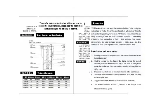
Basic Structure and Specification Technical ParameterDescriptionYXVM series vertical mixer adopt the working principle of spiral mixing;the material get to the top through the spiral axis,then get down as Umbrella state and cycling continuly to mix even.YXVM series vertical mixer has so many advandages,such as Time automatic operation、overloading protection、less occupation of land、large voitage、Low power consumption、less labor and easy operation 、mixing even,etc. it is widely used in the fields of plastic pellet、crushed material、films.Installation and Instruction:1.Properly connected to the power,check if Abnormal debris exsit in thebucket before start.2.Start to operate free to check if the Spiral running the correctdirection; if reserve direction,please adjust The order of three-phase power line; make sure the spiral running correctly, and everything be OK to start.3. Prohibition to put into iron or other hard material in the Cast hopper.4. Stop soon when abnormal noise appears,start again after checkingand solving the error.5. Suggest to install the machine in the independent workplace.6. The material can’t be bucketful , 90%will be the best,or it willinfluence the mixing quality.Thanks for using our product,we will do our best to service for you.Before use,please read the instruction carefully,then you will be easy to operate.电器原理图:Maintenance:1.Suggest that it has Higher ventilation space above themachine ,then the work heat of motor can be sure to emit,it can extend the motor worklife.2.According to the production state, it should timely (30days) add lubricating oil to nozzle tip of the bottombearing.3.Regularly check if the belt is loose. If it is loose, it shouldLoosen the motor mounting bolts,then adjust the motoeout with special tools till the belt tension.4.If the machine is used to mix other color material, it needsto clean the bucket. Please clean with air pressure gunand mop.It can’t rinse water directly,or the chassis will getrusty.5.Please shut off the power when the machine don’t use forlong time.。
Economical Life Extension• Backward compatible with earlier D20 RTUchassis (VME and non-VME), simplifying upgrades and reducing associated time and costs • Modular hardware platform combines functions onto a single board, simplifies ordering, eliminates add-on expansion memory cards and cables, and decreases service time and maintenance effort • Employs super capacitors instead of lithium batteries, extending operation and availability, retaining system clock and eliminating the need to plan for and replace dead batteriesCyber Security and Risk Management• Supports Cyber-Ark functionality for increased security while providing remote access • Supports open standard cyber security features that for NERC CIP interoperability • Syslog integration into enterprise system assists with audit compliance • SSH and SFTP provide secure firmware and configuration file transferFlexible and Reliable• Configurable redundant and dual LAN options with built-in dual Ethernet communication ports • Alias IP address provides simultaneous communications with both redundant and dual LAN devices • Multiple and simultaneous SCADA protocols for communication to multiple masters • Robust, advanced automation applications based on more than two decades of successful experienceSimple to Advanced Substation Automation ControlDistribution and transmission industries are under pressure to ensure that their grids are reliable and to prolong the usability of their assets. Data from these assets can be collected, aggregated and processed, to provide visibility of system conditions. The Multilin TM D20MX Substation Controller is a specialized computing platform designed to execute communications and energy management applications for the monitoring and control of electrical substations. The D20MX is capable of amalgamating data from multiple slave devices and D20 I/O modules connected via communication channels into a single database using various protocols. The D20MX can execute local logic, compile data, process it through one of multiple applications and report the results upstream to master stations through different server protocols. The D20MX represents the next innovation in GE’s cyber secure RTU technology for NERC-CIP environments. The D20MX is built upon the field-proven Multilin D20 technologies and continues the tradition of reliable automation and control through high quality and long term product availability.Key Benefits• Reduces legacy D20 RTU upgrade expenditures by over 50% through backwards compatibility with existing D20 installed accessories, such as chassis, modems and D20 I/O peripheral modules • Minimizes operation and maintenance costs of existing D20-based SCADA infrastructure by leveraging existing designs, processes and infrastructure • Introduces a new and modern network security feature suite that enables effective compliance with NERC ® CIP requirements through the application of native cyber security features built into the D20MX Substation ControllerApplicationsData ConcentratorAutomatically consolidates collected information from intelligent electrical devices (IEDs), such as relays and meters, and communicates to SCADA, EMS, DMS and Data Historian systemsProtocol ConverterTranslates different data message formats between devices to support interoperabilityLocal Automation PlatformImplements popular distribution automation applications such as capacitor bank control, outageprevention programs, feeder resource optimization and control interlocking, inhibition and subgroupingMultilin ™D20MXAdvanced ControllerThe Multilin D20MX Substation Controller collects, filters, and sorts data from a wide range of intelligent devices (RTUs, relays, meters) in the substation. The D20MX preserves original data time stamps for accurate sequence of event (SOE) logs, allowing data from large diverse geographic regions and time zones to be analyzed in extreme detail. Data can be presented simultaneously to multiple SCADA hosts. The D20MX comes with a built-in suite of protocols and security applications to facilitate integration with various substation devices and SCADA hosts.D20MX is the sixth generation of D20 CPUs designed to provide a smooth migration path for D20 users to extend the life of aging D20 systems. It introduces a new and modern network security feature suite that enables effective compliance with NERC-CIP requirements, using open and trusted standards and protocols that allow integration with modern cyber security systems and tools.D20MX Controller Main Connectivity ApplicationsAdvanced Substation Controller ConnectivitySample Enterprise Protocols:• DNP3 serial and Ethernet [TCP/UDP/IP]• Tejas V • HR6000/XA-21• Modbus serial (RTU or ASCII)• IEC 101/104• LG-8979 • PG&ED20MX Media Connectivity:• 7 serial ports (RS232)• Built-in dual Ethernet ports• (10/100/1000 Base TX or 100 Base FX) Dual D.20 communication portsSample Device Protocols:• DNP3 serial and Ethernet[TCP/UDP/IP]• Modbus serial (RTU or ASCII)• IEC 101/104• SEL• IRIG-B supportV1.4B021-0DNP3 DPA •B021-0DNP3 DPA •A068Modbus DPA •A033-5Tejas V DPA •A185-0LG 8979 DPA •A009PG&E DPA•A101-0IEC 60870-5-101/104 DPA •A003Harris 6000/XA-21 DPA •A135-0 Modbus TCP/IP DPA •A023 CDC TYPE I DPA•V1.4B023-0DNP3 DCA •A059Modbus DCA •A078-0SEL DCA•B060-0IEC 60870-5-101/104 DCA •A131-0Modbus TCP/IP DCA•A018Quantum Meter Scanner DCA •A194-0COOPER 2179 DCA •B080-0IEC 60870-5-103 DCA•GE P/N DATA TRANSLATION APPLICATIONS [DTA]V1.1V1.2V1.3V1.4A030Accummulator Freeze DTA •A035Analog Reference DTA •A118Failover DTA•A184-0General Alarm DTA •B009Mailbox DTA•A123-0NGC General DTA•A113Programmable Synchro Check Relay DTA •A036Prologic Executor DTA •A027SOE Logger DTA•A088-0Substation Maintenance DTA •A027-1Communications Watchdog •A083-0Calculator DTA •A195Redundant I/O DTA •B099-0SNTP Client DTA•B082-0LogicLinx Executor DTA•A041-1Proportional Integrator Derivative Control DTA •B148Time Zone and DST Setting DTA •A017DNP V1.00 DATA LINK DTA•A161-0 Secondary Master Trip/Close DTA •A121-0Automatic Frequency Selection DTA •A048Status Combination DTA •A104-0N Alarm Grouping DTA•A193-0Top of the Hour Analog Averaging DTA •A186-0Western Power Distribution (WPD) DTA •B119-1NLAN Redundancy Manager DTA•IEDs/MetersProtection RelaysBay ControllersD20MX Classic and Advanced Automation ApplicationsD20MX CLASSIC APPLICATIONSA009PG&E DPAA033-5Tejas V DPAA036Prologic Executor DTAA113Programmable Synchrocheck Relay DCA A185-08979 DPAA194-0COOPER 2179 DCAA199-0HR6000/XA-21 DPA D20MX CLASSIC APPLICATIONSA041-1Proportional Integrator Derivative Control DTA A018Quantum Meter Scanner DCAA023CDC Type I DPAA017DNP V1.00 Data Link DTAD20MX ADVANCED AUTOMATION APPLICATIONSB082-0Logiclinx Executor DTAUpgrade of Legacy D20 RTUsThe Multilin D20MX is more than an RTU. It’s a commitment to the ongoinglong term availability of GE’s automation products. Utilities have largeinvestments in hardwired automation systems.Like everything else, this industrial equipment has a lifecycle that movesfrom infancy to normal operation, and eventually to the wear out stages. Asa piece of equipment ages it fails more frequently, takes longer to repair, andeventually reaches the end of its life. Re-design and forklift replacementsrequire utilities to re-engineer substation designs, replace field wiring, andretrain staff to manage and maintain the system, which is a costly endeavor.The Multilin D20MX provides a cost-effective alternative to upgrades of legacyD20 RTUs. This means that the investments made in GE’s automation systemskeep paying dividends beyond their originally projected end of life. Simplyreplace the failed or end of life Multilin D20 processor module with a MultilinD20MX and migrate the device configuration to extend the life of the existingD20 Controller. Add cyber security features for integration into NERC-CIPenvironments. As technology changes with market demands, GE continues toinvest in a partnership with their customers through advanced modular designprincipals.Integration of D20 Substation Controllers into NERC-CIP EnvironmentsThe Multilin D20MX supports a comprehensive set of security functions to allow a seamless integration with existing IT department policies. Built-in cyber security features, such as Remote Authentication Dial-In User Service (RADIUS), Role Based Access Control (RBAC), and user activity logging, provide a complete security toolkit required to enable effective compliance with NERC-CIP requirements, using open and trusted standards and protocols, that allow integration with modern cyber security systems and tools. RADIUSRADIUS is a client/server networking protocol that provides centralized authentication, authorization, and accounting (AAA) management for computers to connect and use a network service. With RADIUS each user in your system has their own unique identification login, allowing you to control who gets access to what devices from where. RADIUS provides centralized AAA management for computers to connect to the D20MX.If one of the current users of your D20MX leaves your company, you can lock down access to all the devices in your network from a central location. That user instantly loses access to every D20MX, while other users remain able to do their jobs without any adverse effects and costly password change programs.AAA Network AccessRadius servers use the AAA concept to manage network access by following a few steps referred to as AAA transactions.AuthenticationThe user sends a request to gain access to a particular resource using access credentials, typically, in the form of user name and password.The RADIUS server verifies the user’s credentials and accepts or rejects access. The D20MX supports primary and secondary RADIUS servers. If for any reason the D20MX is not able to authenticate the user against the RADIUS servers, the D20MX verifies the user’s credentials against a local password file.AuthorizationIn a typical centralized user authentication system, access terms are defined on a per user basis. For example, the following authorization attributes may be associated for a specific user:• Specific D20MX IP address to be accessed by the user• Role ID assigned to the user, where role ID defines which commands and displays the user is able to access on the D20MX• Allowed time-of-day during which users can access the network AccountingWhen access is granted to the user, their activity can be registered for security, system integrity monitoring and statistical purposes. For example, the following user’s activity can be recorded:• User information• Login time stamp• Logout time stampThe D20MX provides accounting information by logging the user’s activity to a remote syslog server.RBACRBAC is achieved using RADIUS or the D20MX’s internal database, ensuring only authenticated and authorized users gain access to the system.When you configure the D20MX to use RADIUS, each D20MX user is identified by a role ID, which is an integer number provided by the RADIUS server. The D20MX makes your life easier by including a pre-configured default RBAC model.When using RADIUS, revoking user privileges system-wide is as simple as updating the centralized user database, saving you time and money.Advanced AutomationSince releasing the first generation D20 back in 1988, GE’s automation experts have learned a lot. Through challenging projects and installations across the globe, the D20 has evolved into a leader in substation automation. The culmination of that experience is the sixth generation, the Multilin D20MX. The following are a sample of the advanced automation features available today.Substation MaintenanceIf there is one thing operators hate, it’s false alarms. The D20MX can suppress reporting of input points while they are unavailable during maintenance. This allows users to disable groups of analog and digital input points by ignoring their actual data and quality changes within selected applications. While points are suppressed, a predefined suppression value and the point suppression quality flag are provided instead. This is useful during maintenance operations to prevent spurious OFFLINE alarms and inaccurate readings while devices are powered off or disconnected during the execution of maintenance activities.Centralized Authentication and Authorization1. Login attemptAccumulator FreezeMonitoring constantly incrementing and changing values, such as time of use, and energy consumption across a system, makes accurate comparisons of data a time-consuming effort. GE’s accumulator freeze application simplifies this process automatically by capturing the instantaneous value of accumulator records across the system at the same point in time, giving engineers and operators a clear understanding of the state of their system.A popular example of the use of accumulators is energy metering, where pulse streams from meter pulse generators is proportional to energy flow. This feature allows users to define groups of accumulator points whose values are frozen periodically or on demand.Alarm ManagementThe D20MX manages alarms based on real substation experience. This application allows user-defined logical grouping of individual digital inputs to generate general alarms based on the status of the signals monitored within each group. Alarm groups are user-definable, with up to 32766 groups allowed. Status inputs may belong to as many groups as required.The great flexibility of this application ensures that each group has its own meaningful description and configurable latching or non-latching operation modes. Latching alarms require operator acknowledgement for optimized management of critical conditions in the system.System RedundancyAlthough the D20 family of RTUs is legendary for quality, GE has prepared for those rare cases when a processor is unable to function. Through time tested and utility accepted redundancy mechanisms, the D20MX is designed for high availability requirements. In redundant processor mode, one device stands waiting, ready to take over, should the other unit stop functioning.Dual D20MX units can be deployed, creating a redundant system where accumulators are automatically synchronized between the two systems and configurations are synchronized on demand. Serial communication links are automatically switched between the units based on system health.The D20MX has redundant Ethernet, enabling automatic switchover between two sets of Ethernet switches, ensuring there is no single point of failure in the system.Control LockoutThe control lockout feature ensures that only a single master station can access a group of controls at one time, and can lock out groups of controls to allow for safer local maintenance. Users can create custom control groups. Any digital output can be included in any control group.Analog Inputs MonitoringGE’s analog reference provides enhanced and simplified monitoring of analog input monitoring equipment. Operators define a reference value used to compare against monitored signals. The application reports failures in analog input hardware, allowing effective maintenance of the monitoring devices, reduced downtime and increased reliability of the system.SGConfig Setup SoftwareThe Multilin SGConfig software integrates support for the complete portfolio of GE’s Substation Controllers, including the D20MX series. The SGConfig software introduces an updated graphical user interface while maintaining configuration processes and workflows available in the ConfigPro setup software.Convenient access to product documentation and screencasts is provided directly from the SGConfig software. (Screencasts are short instruction videos on popular setup processes.)Typical Architecture for Redundant D20 Substation Control SystemRS232 CommunicationsD20MXSubstation IEDEthernet Switch BEthernet Switch ALAN A LAN BSubstation IEDD20MXSubstation IEDHardware OverviewFully Equipped Out-of-the BoxPrevious generations of D20 RTUs required add-on system components and software to support Ethernet communications and optional memory expansion. The new D20MX is equipped by default with integrated memory, 10/100/1000BASE-TX or 100BASE-FX IEEE 802.3 compliant communications and a core load firmware with a comprehensive set of key substation automation applications.Backwards CompatibilityThe Multilin D20MX is an embedded single board computer powered by a 667 Mhz power PC CPU pin-for-pin compatible unit with existing D20 VME and non-VME D20 processors and accessories, such as chassis, D20 remoteI/O peripherals, modems.Compatible with classic VME and non-VME D20 chassisPCI mezzanine card site for future expansionSuper capacitor enables maintenance-free, battery-lessoperationBuilt-in 2 x 10/100/1000BaseTX or 2 x 100Base FX Ethernet portsIntegrated CPU, memory, Ethernet and media interface in a single D20MX processorPROCESSOR: 667 MHz embedded PowerQUICC II ProMEMORY• 1024 MB of 266 MHz DDR2 RAM with ECC • 16 MB NVRAM for persistent event storageSTORAGE• 8 MB boot flash• 256 MB firmware flashOPERATING SYSTEM: VxWorks LED INDICATORS System status: Power, Ready Ethernet port status: Link and Activity status per portPower supply: PowerIRIG:Flashes when activeNETWORK CONNECTIONS• Dual redundant Ethernet interface• Twisted Pair• 10/100/1000BaseTX (Isolated RJ-45 connector)• 100BaseFX (Fiber Optic: 1300 nm, 50/125 µm, 62.5/125 µm multi-mode duplex fiber cable, ST connectors)SERIAL COMMUNICATIONS• D.20 Link, 2 channels • Data rate: 250 kbps• Surge protected to ±2000 V peakRS-232, 7 CHANNELS• 5-signal (TXD, RXD, RTS#, CTS#, DCD#) DTE ports • Data rate: independently-selectable; refer to the application configuration guides.MAINTENANCE PORT• RS-232, 1 channel/ 2 ports • 2-signal (TXD, RXD)• Data rate: 19200 (default)ELECTRICALRATED POWER SUPPLIES AC-DC:100 to 240 V AC (±10%) 143 W output maximum Minimum/Maximum AC voltage: 90V AC / 265 V AC100 to 300 V DC (±10%) 143 W output maximum Minimum/Maximum DC voltage: 88 V DC / 330 V DCDC-DC:20 to 55 V DC (±10%) 135 W maximum Minimum/Maximum DC voltage:18 V DC / 60 V DCPEAK INRUSH CURRENT AT 25 °C ON COLD START AC-DC : 50 A, max at 230 V AC DC-DC:50 A, max at 230 V ACRATED FREQUENCY:50/60 Hz nominal (47 to 63 Hz)(AC/DC)PHYSICAL OVERALL HEIGHT: 40.34 mm (1.588 in.)WIDTH : 261.87 mm (10.31 in.)DEPTH: 160 mm (6.3 in.)D20MX WEIGHT: 0.7 kg (1.65 lb.)FIBER CARD WEIGHT :0.2 kg (0.35 lb.)BATTERY SHIPPING RESTRICTIONSThe D20MX does not contain a battery and is therefore not affected by US DOT or ICAO shipping restrictions.MATERIAL/FINISH: G alvannealed steel with black power coatKIT PACKAGE LENGTH: 49.5 cm (19.5 in.) WIDTH: 34.3 cm (13.5 in.) HEIGHT: 15.2 cm (6 in.) WEIGHT:2.54 kg (5.6 lb.)ENVIRONMENTALOPERATING TEMPERATURE: 0°C to +70°CNote: Do not operate the D20MX above 60°C for extendedperiods of time as this will shorten the life of the supercapacitor and reduce the backup time of the real time clock.HUMIDITY RATING:5% to 95% relative humidity, non-condensingENVIRONMENTAL RATINGINGRESS PROTECTION: IP30 (IEC 60529)INSTALLATION/OVERVOLTAGE CATEGORY: CAT II (2)POLLUTION DEGREE: 2USE:Indoor use onlyOPERATING ALTITUDE: M aximum altitude 3000 m [9480feet] above sea level MTBF (MIL-HDBK-217): D20MX Processor Board• Non-VME with 10/100/1000BASE-TX copper: 449,616 hours at 40°C• Non-VME with 100BASE-FX fiber optic: 265,657 hours at 40°CSOFTWARE CONFIGURATION:P erformed using SGConfig 7 and higherTechnical SpecificationsGEA-12711E(E)Ordering CodesMultilin D20MXFuture FeatureUNot requiredUpgrade Kits Order CodesUpgrade kits include the necessary items required to upgrade existing D20 RTUs including:• New D20MX CPU [526-3001 or 526-3003 or 526-3005]• Blank Plates [953-1014]• Multilin Products Documentation CD [581-0002]• Multilin D20MX Documentation CD [588-0075]• Ferrite Core for D20 Power Wiring [460-0073]• 0V Cable [975-1237]• Null Modem Cable [977-0529]IEC is a registered trademark of Commission Electrotechnique Internationale. IEEE is a registered trademark of the Institute of Electrical Electronics Engineers, Inc. Modbus is a registered trademark of Schneider Automation. NERC is a registered trademark of North American Electric Reliability Council. NIST is a registered trademark of the National Institute of Standards and Technology.GE, the GE monogram, Multilin, FlexLogic, EnerVista and CyberSentry are trademarks of General Electric Company .GE reserves the right to make changes to specifications of products described at any time without notice and without obligation to notify any person of such changes.。
Spiral chute1、product descriptionSpiral chute is integrated spiral separator, spiral chute, shaker, centrifugal concentration machine characteristics of the equipment, mining, mineral processing is the best equipment, especially the seaside, riverside, sand beach, the stream of placer mining is more ideal. The product has the advantages of reasonable structure, simple installation, covers an area of small, simple operation, stable ore beneficiation, clear, large processing capacity, high efficiency enrichment ratio high, high recovery rate, reliable operation characteristics. Have weight light, moisture-proof, rust-proof, corrosion resistance, of the feeding quantity and concentration, particle size, quality of volatility adaptability is strong, no noise.2、Separation principleSpiral chute is a membrane flow gravity separation equipment, the selection principle is the use of useful minerals and gangue in proportion, particle size, shape differences, in rotating inclined flow by gravity, centrifugal force, hydrodynamic pressure and friction force with different groove face, realize the useful minerals and gangue stratification, branch tape sorting. Heavy, coarse granularity, fast sedimentation of particles gradually moved towards the spiral groove inner edge, the proportion of small, fine particle size, particle sedimentation slow gradually moved to the spiral groove edge, gradually banding, culminating in the spiral groove end by cutting ore tank is respectively connected out, to realize separation.3、ApplicationThe sorting equipment for grain size 0.3--0.02 mm fine iron ore, titanium ore, chromite, pyrite, zircon, monazite, rutile , phosphorus ore, tungsten, tin, B mine of tantalum niobium ore with the difference of specific gravity, and other non-ferrous metals, rare metals and non-metallic mineral. The sorting process with a stable, easy to control, to allow changes to the mineral concentration range, high enrichment, high recovery rate, small occupation area, little water consumption, simple structure, no need of power, large processing quantity, simple installation, convenient operation, small investment, quick advantages.4、The method of useThe spiral chute is erected, calibrated vertical line, with metal or wood fixed in position, by the sand pump will ore to spiral top two inlet, adding supplemental water, mineral ore concentration regulation paddle, paddle down naturally from high swirl, in rotating inclined flow produces a kind of inertial centrifugal force, with ore proportion, particle size, shape differences, swirl through the action of gravity and centrifugal force, will be mine and sand separating, concentrate into the concentrate pipe connected with a hopper, tailings into tailing bucket a pipeline is connected to a sand pool, then the pump discharge, finished processing the whole process.5、Structure and technical parameterMainly by the ore separator, cross, to mine groove, helical groove, cutting trough, pick ore bucket and slot pillar of seven components. The helical groove is spiral chute of the main components, each spiral chute is 2 -- 4 head spiral groove, each head spiral groove is composed of 5 spiral plates (according to mineral properties and beneficiation process need, after tests also consider 4 circles, in order to reduce the equipment height) spiral plate by bolts are fixed together, spiral sheet is made of glass fiber reinforced plastic (FRP) made, light weight, anti-corrosion, moisture-proof, anti deformation and strength.6、InstallationSpiral chute installation procedures and requirements:1)First check the glass steel spiral slice quality (especially the work surface quality), sizeand shape to meet the requirements for assembly2)Screw plate connecting bolt hole by the general factory in advance with a drill. If themanufacturer has no processing is required, according to the same template drilling, in order to ensure good interchangeability.3)Bolt the five coil sheet are connected into a group of spiral groove, level set, twoadjacent flange connection within the surface smooth transition is connected, special attention should be paid on the surface may not be lower than the corresponding lower sheet surface. Along the diameter direction.(the slot width direction) to edge alignment as the standard, do not allow plate rim inside, so the installation is intended to prevent the occurrence of ore fluid splash. Joint gap, with putty.4)The coupled five of a group of four (or two or three) spiral groove rotating togetherinto a desired shape, distribution.5)The four roots (three) column is respectively arranged in four (or three, two) spiralgroove, bolt the spiral groove and the pillar is fixed, then install the cross (tripod), so that each spiral along the park are cloth, then all bolts. After installation, spiral plate tomaintain the natural shape, with no obvious variant.6)Would give mine groove and product interception groove are respectively arranged inthe spiral groove of the head end and the tail end to ensure that the connection of close water leakage. If there is a gap, by coating sealing. To ensure the smooth transition of groove surface.7)To mine even divider and product assemble bucket and the slot bracket is notconnected, free placed on the bracket, the installation should pay attention to in the chart are position. Each row of tube to distributor are respectively aligned with corresponding to the ore tank.6-S shaking table1、ApplicationThe 6-S shaking table is one of the main equipment of gravity concentration, it is widely used in separating tungsten, tin, tantalum, niobium, gold and other rare metals and precious metal ore. Can be used for roughing, concentration, scavenging different operations, separating coarse sand (2-0.5mm) (0.5-0.074mm), fine sand, clay (- 0.074) of different grain grade It can also be used to separate iron, manganese ore and coal. When processing tungsten, tin ore, the table effective recycling particle size range for the 2-0.22 mm.2、PerformanceThe shaking table is in the beneficiation process is complex a tilt bed plane, ore particle swarm from the bed surface angle to the trough into, at the same time by lateral flushing water supply to the water tank, and the mineral particles in gravity, lateral flow momentum, bed reciprocating asymmetric motion produced by the inertia and friction effects next, according to the proportion and hierarchical granularity, and along the bed surface for longitudinal movement along the inclined bed surface and transverse motion. Therefore, specific gravity and particle size of different mineral particles along the direction of movement of the respective gradually by the A side to side B fan-shaped shed, concentrate and tailings from the end side of the discharging end is divided into different, concentrate, middling and tailings.6-s has a double high rich ore ratio, high separation efficiency, safeguards easily, convenient for adjusting the stroke. In change cross fall and stroke is still maintain the surface of bed movement balance, the spring is placed in the box body, compact structure, and can in turn draw final concentrate and tailings.3、Classification1)According to the different position of ore, shaker can be divided into right and left type cradle type cradle two forms. The right type cradle for the ore location for the rocking mechanism is on the right side, left type cradle to mine is located in the left.2)6-S shaker can be divided into fixed shaking table,channel bar shaking table,big channel steel shaking table.3)According to the concentration particle size, divided into coarse sand table, sand table and slimmer three.4、StructureThis table is mainly composed of a bed head, motor, adjustable slope, the bed surface, mine shafts, sink, and reflex and lubrication system of eight components.The surface of bed longitudinal reciprocating motion through a crank connecting rod type driving mechanism to realize. The electric motor through the belt drive to make the big belt wheel drives the crankshaft to rotate, the rocker made subsequently moves up and down, rocker downwards, elbow board drive rear axle and the reciprocating rod moves backwards, the spring being compressed. The bed surface is through linkage seat and a reciprocating lever connected, so this is also so the bed surface for backward movement, when the rocker upward movement, due to the tension spring drive, the bed surface will move forward.5、Specification6、Installation and cautions1) On the basis of drawing, reserved anchor screw holes or pouring good foundation plate, drilling, hole expansion, the construction of concrete foundation.2) The shaker frame placed on the basis, make each place, calibration and pad frame beam level.3) The Department of anchor screws tightening, the cradle is fixed on the basis of.4) Mounted on the drag device, bed surface, bedside and bed and the bed surface connecting rod, attention should be to the front to bedside flywheel.5) Connect the switch of the motor insurance, check whether the motor leakage, and then good motor wire.6) The bed surface is not strong beat, collision; not in high temperature and heavy pressure; avoid oil pollution and sun and rain, prevent degeneration.7) After the installation, a detailed examination, the confirmation, removal of equipment and surrounding sundries.8)Roller with 10-20 G oil, not to splash as well. The seat sliding rack injection oil to drown the sliding bearing and the lower bearing contact fit; lever type rocking frame bearing has been manufactured with good lithium grease.9)Put the washing water air machine test machine operation, observation and examination: starting and operation, the moving parts are not loose fever or unusual sounds.10)Empty test machine to normal, can load test machine, according to the selected minerals, inspection and adjustment of the stroke, stroke, springs, bed longitudinal slope and transverse slope so as to achieve the optimal separation effect. After normal cleaning, it can be put into production.7、operation and maintenance1)Feeding volume and concentration of proper, if give mine too large volume, concentration, recovery rate. 2)The bed surface transverse slope large, flushing water should be smaller; slope is small, flushing water shall be selected.3) Stroke and frequency of stroke should be adjusted properly. Stroke is too small too big, affected grain stratification. To change the diameter of a motor belt pulley, adjustable stroke Adjusting spindle and the set of eccentric combination, can have different stroke,Permanent magnetic separator1、Range of applicationThe series of magnetic separator for sorting magnetic minerals, non-metallic materials and waste materials deironing. Such as: reduction of titanium magnetite, iron ore smelting in front of the purifying selection, ceramic clay, feldspar, quartz, iron ore, coal and other materials in addition to iron.2、The structure and working principleCT series cylinder type permanent magnetic separator, drum body and a groove near the magnetic system parts are made of non-magnetic material of stainless steel, cylinder end cap cast in aluminum, and other ordinary steel production. Equipment structure is composed of a machine frame, body, a cylinder, a magnetic system, power plant, feed, water, discharging part. The groove body and cylinder distance according to the mineral separation of lifting adjustment, magnetic angle can be adjusted at.(no water supply device of dry type)1)CTC dry magnetic separator: dry aggregate from the hopper into the cylinder directly to the upper or lower portion of the drum, magnetic mineral particles are magnetic in the surface of the drum, winding drum rotates to the edges of the natural unload magnetic system. Non magnetic mineral particles by the action of gravity and centrifugal force and magnetic products into different ore bucket. Magnetic products magnetic products and is arranged in the middle of ore isolation plate, according to the mineral material selected to adjust the situation.2)CTB semi-counter current magnetic separator magnetic lines in the lower part of drum. Pulp from the tank into the lower part of the lower roller, non-magnetic minerals in the direction of movement and the rotation of the drum in the opposite direction, magnetic minerals moving direction and rollers rotate in the same direction. The lower part of the spray pipe body is inserted, is used to adjust the separating operation of slurry concentration, the slurry dispersed into loosely suspended state into the separation space. The magnetic particles in the magnetic system of magnetic field force, is absorbed on the surface of the roller, roller together with the upwardly mobile. In the moving process, because the magnetic lines of alternating polarity, so that the magnetic mineral particles into a chain of turning, in the turning process, the inclusions in the magnetic mineral particles in non magnetic mineral impurities is cleared, so as to effectively improve the purpose of magnetic products. Semi countercurrent magnetic separator for mineral slurry concentration and granularity is sensitive to change, when the concentration is too large or grain through the metropolitan influence index of mineral processing.3)CTS downstream separator: feeding direction and the direction of rotation of the drum or magnetic mineral moving direction. The pulp comprises feeding bucket directly into thecylinder below the magnetic system, non magnetic particle and magnetic weak mineral particles from beneath the tank bottom roller two and the gap between the discharge, magnetic mineral particles are sucked on the surface of the cylinder, with the roller to rotate together to the magnetic system edge discharge, magnetic ore discharging position is provided with a discharging water pipe. Downstream separator on mineral beneficiation of wide adaptability, easy separating space is smooth without obstruction, particularly applicable to contain magnetic minerals a larger proportion of the magnetic separation process.4)CTN upstream separator: feeding direction and drum rotation direction or magnetic material moves in the opposite direction. The pulp comprises feeding bucket directly into the cylinder below the magnetic system, non magnetic particle and magnetic weak mineral particles from tank bottom hole discharging tailings, magnetic mineral particles with the roller against the feed direction to give mine is discharged to the magnetic ore groove, for the reduction of magnetic products with non-magnetic mineral, in magnetic ore unloading mounted before the cleaning water pipe, magnetic ore discharging position is provided with a discharging flushing pipe. Countercurrent separation machine due to the magnetic ore discharge end distance to mine mouth close, magnetic turning effect is poor, so the magnetic ore grade to be slightly lower, but its tailings ore export far away from the mouth, the pulp after longer divided districts, increases the magnetic mineral particles are magnetically attracted to opportunity, all the magnetic separator magnetic product recovery rate is quite high, counter flow type magnetic separator suitable for only require nonmagnetic product precision of various minerals.3、Specification4、Installation and use1) At first machine installed must check the transport loading and unloading is loose, damaged.2) The horizontal position, implement, conventionally grounded.3) Check, adjust the magnetic system to the fixed position processing and working distance.4) Before the first test machine, drum empty running again, water supply, feeding, everything is normal, and then evenly feeding load test machine. According to the material separation requirements for adjusting the output, quality, recovery rate.5、Preventive maintenance1) Removing: drum removable from the frame, standing on a stable level of supporting frame. Have a head driving device placed below.2) When hoisting drum magnetic parts do not close to the strong magnetic tool or magnetic materials.3) Will fixed aluminum cover fastening screw removal. The 4 screw mount aluminum end cover removing hole. Parallel to the rotating 4 pearl will cover up after unloading, and then remove the lower end cover fastening screw, can come up with a stainless steel cylinder. Aluminum cover middle small iron cover for the bearing cover and cover solid screw.4) The assembly must be completely to the magnetic surface and stainless steel inner cylinder of clean.5) Transmission gears, bearings, reducer shall be regularly maintained and filling calciumbase grease lubricating oil.6、Cautions1) Strong magnetic tools, articles shall not be close to the magnetic system.2) Do not beat, collision stainless steel tube.3) Super size mineral, not into the machine, so as not to get stuck or wear of stainless steel copper cylinder.4) Abnormal sound, should be excluded.Ball mill1、Purpose and use scopeBall mill is the material being broken, and then smash the key equipment. Mill widely used in cement, silicate products, new building materials, refractory materials, fertilizer, black and non-ferrous metal processing and glass ceramic production industry, for all kinds of ores and other materials may be grinding of dry or wet grinding.2、Working principleThis machine is a horizontal cylinder rotating device, outer gear transmission, the warehouse has stepped lining board or corrugated liner, built in different specifications of steel balls, the rotation of the cylinder to generate centrifugal force will bring the steel ball to a certain height after the fall, the material produces severe impact and abrasive. Powderthrough the discharge grate discharge, then finish grinding operation.3、StructureThe equipment consists of feeding, discharging part, turning part, a transmission part (reducer, small transmission gear, motors, electrical control) and other major parts. Hollow shaft with steel castings, the liner is detachable, rotary gear hobbing with casting, cylinder liner wear studded body, has good abrasion resistance. The machine running stable, reliable work.4、Specification5、Installation and adjustment1)The basic requirements of installation:A、Bill mill should be installed on a solid concrete foundation;B、Ball mill cylinder should be installed after the ground with sufficient height, so as to facilitate the replacement of cylinder liner and grinding body, and a screw bolt lining board;C、Our generation base map, there are parts of a machine center line and the center line and the installation of anchor bolt anchor bolt size, random supply, base map size only remaining user base design reference, not for construction of.2)General requirements for the installationA、Machine parts are in the transport loading and unloading damage, such as damage should be trimmed.B、Machine parts are in the transport loading and unloading damage, such as damage should be trimmed.C、All the connecting bolts should be uniform, firmly tightened。
CONTENTSCONTENTS (2)BASIC FUNCTION (3)Basic Parameters (3)OPERATION INSTRUCTION (4)How to Use (4)Maintenance (4)SIMPLE MAINTENANCE GUIDE (5)MECHANCIA BLUE PRINT (6)BASIC FUNCTIONT-500 ~ T-1200 Thermocompressors are designed for veneers molding process in the generalplywood production line.It provide a high temperature and high pressure condition so the shapeless veneers can turninto a whole piece and ready for further process.The thermo energy was based on steam power. To make it work, stack the cold-pressedveneers into the machine. Turn on the power and wait for glue’s solidification. Grey board’srequirement is based on the veneers’number. For common usage, 15-20 grey boards aresuggested to process with 16-21 veneers.Basic Parameters*Parameters above based on the metric systemOPERATION INSTRUCTIONHow to UseThis thermocompressor is highly advanced in structure. It is controlled by a PC appliance andcan be operated by single or multi engineers.1.Close the thermo compress plate before turn on the machine.2.Import the hot oil; preheat the plate to the desired temperature.3.Stack the cold-pressed veneers into the right position.4.Set the time limit.5.Press the Rise button to raise the compress plate one by one.6.The job will be done automatically.MaintenanceTo increase machine’s service life, proper maintenance is necessary.1.Check for any leakage point before and after use.2.Check the dynamo and pump valve if they were working properly.3.Check the oil level regularly,fill the tank to standard level if necessary.4.Filter the pump oil periodically.5.Keep the machine and pump station clean.e only certified Antifraying Hydraulic Oil to fill the machine. Use #46 hydraulic oil inwinter and #68 hydraulic oil in summer. Take 70℃as a temperature limit for thehydraulic oil.SIMPLE MAINTENANCE GUIDEMECHANCIA BLUE PRINTLift Cylinder Lowering Valve High Pressure Decompression ValveSlow Down ValvePFVAuto/ManualRise TA1Down TA1Dwell Time UpLow Oil Pressure GaugePressure Relief GaugeHi Oil Pressure Gauge NCStopHi Oil Pressure Gauge NODwell Time UpRoute。
ioLogik R1200SeriesRS-485remote I/OFeatures and Benefits•Dual RS-485remote I/O with built-in repeater•Supports the installation of multidrop communications parameters•Install communications parameters and upgrade firmware via USB•Upgrade firmware through an RS-485connection•Wide operating temperature models available for-40to85°C(-40to185°F)environmentsCertificationsIntroductionThe ioLogik R1200Series RS-485serial remote I/O devices are perfect for establishing a cost-effective,dependable,and easy-to-maintain remote process control I/O system.Remote serial I/O products offer process engineers the benefit of simple wiring,as they only require two wires to communicate with the controller and other RS-485devices while adopting the EIA/TIA RS-485communication protocol to transmit and receive data at high speed over long distances.In addition to communication configuration by software or USB and dual RS-485port design,Moxa’s remote I/O devices eliminate the nightmare of extensive labor associated with the setup and maintenance of data acquisition and automation systems.Moxa also offers different I/O combinations,which provide greater flexibility and are compatible with many different applications.Easy-to-Use Software Interface for Easy MaintenanceWith Moxa’s easy-to-use ioSearch software,you can quickly access all of an ioLogik R1200device’s status information and settings with a user-friendly graphical user interface.Furthermore,ioSearch also provides an easy method for updating firmware for all ioLogik R1200devices over an RS-485network,so you can even update your firmware remotely.The free and easy-to-use ioSearch software reduces the maintenance time and labor required to set up your communication interface.When more than one ioLogik R1200are on the same RS-485network,you no longer need to turn hundreds of dials during setup.Instead,simply configure and duplicate each ioLogik R1200’s baudrate and mode through the graphical user interface.This convenient software feature reduces maintenance engineers'effort,and greatly simplifies upgrading your device's configuration compared with more traditional methods.Innovative Hardware Design Reduces Deployment Effort and Enhances Maintenance EfficiencyWith the industry’s first RS-485serial remote I/O with USB design,Moxa provides an innovative solution for upgrading and configuring RS-485 remote I/O communication devices and firmware.All you need to do is upload the configurations to a USB drive,plug it into the field device,and all the configurations and firmware updates will upload to the field device automatically.Cost-Saving Hardware Design for Backup and RedundancyMoxa’s ioLogik R1200Series provides dual RS-485ports so that when one of your RS-485ports is damaged,you can quickly switch to the other RS-485port for quick testing or repair.RS-485remote I/O devices are already considered a low-cost technology,but with dual RS-485ports,Moxa helps you save a little bit more.With the ioLogik R1200,you can take advantage of our dual RS-485ports to set up wiring,provide computer redundancy,or back up your network using two computer topologies.For wiring redundancy,when your computer detects that one of the RS-485 connections is not responding,it can quickly switch over to the other RS-485line to guarantee continuous communication between field sensors and the central computer.Furthermore,users have the freedom to define the settings.For computer redundancy,the ioLogik R1200provides system operators with a secure backup when one system goes down.SpecificationsInput/Output InterfaceButtons Reset buttonAnalog Input Channels ioLogik R1240Series:8Analog Output Channels ioLogik R1241Series:4Configurable DIO Channels(by software)ioLogik R1212Series:8Digital Input Channels ioLogik R1210Series:16ioLogik R1212Series:8ioLogik R1214Series:6Isolation3k VDC or2k VrmsRelay Channels ioLogik R1214Series:6Digital InputsConnector Screw-fastened Euroblock terminal Counter Frequency 2.5kHzDigital Filtering Time Interval Software configurableDry Contact On:short to GNDOff:openI/O Mode DI or event counterPoints per COM ioLogik R1210/R1212Series:8channelsioLogik R1214Series:6channels Sensor Type Dry contactWet Contact(NPN or PNP)Wet Contact(DI to COM)On:10to30VDCOff:0to3VDCDigital OutputsConnector Screw-fastened Euroblock terminalCurrent Rating200mA per channelI/O Mode DO or pulse outputI/O Type SinkOver-Current Protection0.65A per channel@25°COver-Temperature Shutdown175°C(typical),150°C(min.)Over-Voltage Protection35VDCPulse Output Frequency5kHzRelaysBreakdown Voltage500VACConnector Screw-fastened Euroblock terminalContact Current Rating Resistive load:5A@30VDC,250VAC,110VACContact Resistance100milli-ohms(max.)Electrical Endurance100,000operations@5A resistive loadInitial Insulation Resistance1,000mega-ohms(min.)@500VDCMechanical Endurance5,000,000operationsPulse Output Frequency0.3Hz at rated loadType Form A(N.O.)power relayNote Ambient humidity must be non-condensing and remain between5and95%.The relaysmay malfunction when operating in high condensation environments below0°C. Analog InputsAccuracy ioLogik R1240:±0.1%FSR@25°C±0.3%FSR@-10to60°CioLogik R1240-T:±0.1%FSR@25°C±0.3%FSR@-10to60°C±0.5%FSR@-40to75°CBuilt-in Resistor for Current Input120ohmsConnector Screw-fastened Euroblock terminalI/O Mode Voltage/CurrentI/O Type DifferentialInput Impedance10mega-ohms(min.)Input Range0to10VDC0to20mA4to20mA4to20mA(with burn-out detection)Resolution16bitsSampling Rate All channels:12samples/secPer channel:1.5samples/secOnly one channel enabled:12samples/secAnalog OutputsAccuracy ioLogik R1241:±0.1%FSR@25°C±0.3%FSR@-10to60°CioLogik R1241-T:±0.1%FSR@25°C±0.3%FSR@-40to75°CConnector Screw-fastened Euroblock terminalLoad Resistor Internal register,400ohmsNote:24V of external power required when loading exceeds1,000ohms Output Range0to10VDC0to20mA4to20mAResolution12-bitVoltage Output10mA(max.)LED InterfaceLED Indicators PWR,RDY,P1,P2Serial InterfaceBaudrate1200bps to921.6kbpsConnector Terminal blockNo.of Ports2Parity None,Even,OddPull High/Low Resistor for RS-4851kilo-ohm,150kilo-ohmsSerial Standards RS-485Stop Bits1,2Surge1kVESD15kVData Bits8Serial SignalsRS-485-2w Data+,Data-,GNDSerial Software FeaturesIndustrial Protocols Modbus RTU Server(slave)Power ParametersPower Connector Screw-fastened Euroblock terminalNo.of Power Inputs1Input Voltage12to48VDCPower Consumption ioLogik R1210Series:154mA@24VDCioLogik R1212Series:187mA@24VDCioLogik R1214Series:207mA@24VDCioLogik R1240Series:216mA@24VDCioLogik R1241Series:343mA@24VDC Physical CharacteristicsHousing PlasticDimensions27.8x124x84mm(1.09x4.88x3.31in)Weight200g(0.44lb)Installation DIN-rail mounting,Wall mountingWiring I/O cable,16to26AWGPower cable,12to24AWGEnvironmental LimitsOperating Temperature Standard Models:-10to75°C(14to167°F)Wide Temp.Models:-40to85°C(-40to185°F) Storage Temperature(package included)-40to85°C(-40to185°F)Ambient Relative Humidity5to95%(non-condensing)Altitude2000m1Standards and CertificationsEMC EN55032/24EMI CISPR32,FCC Part15B Class AEMS IEC61000-4-2ESD:Contact:4kV;Air:8kVIEC61000-4-3RS:80MHz to1GHz:3V/mIEC61000-4-4EFT:Power:0.5kVIEC61000-4-5Surge:Power:2kVIEC61000-4-6CS:3VIEC61000-4-8PFMFSafety UL508Shock IEC60068-2-27Vibration IEC60068-2-6DeclarationGreen Product RoHS,CRoHS,WEEEMTBFTime1,239,293hrsStandards Telcordia SR332WarrantyWarranty Period ioLogik R1214:2years2ioLogik R1210/R1212/R1240/R1241Series:5years Details See /warranty1.Please contact Moxa if you require products guaranteed to function properly at higher altitudes.2.Because of the limited lifetime of power relays,products that use this component are covered by a2-year warranty.Package ContentsDevice1x ioLogik R1200Series remote I/OInstallation Kit1x terminal block,12-pin,3.81mm1x terminal block,3-pin,5.00mm1x terminal block,8-pin,3.81mmDocumentation1x quick installation guide1x warranty cardDimensionsOrdering InformationModel Name Input/Output Interface Operating Temp. ioLogik R121016x DI-10to75°C ioLogik R1210-T16x DI-40to85°C ioLogik R12128x DI,8x DIO-10to75°C ioLogik R1212-T8x DI,8x DIO-40to85°C ioLogik R12146x DI,6x Relay-10to75°C ioLogik R1214-T6x DI,6x Relay-40to85°C ioLogik R12408x AI-10to75°C ioLogik R1240-T8x AI-40to85°C ioLogik R12414x AO-10to75°C ioLogik R1241-T4x AO-40to85°CAccessories(sold separately)SoftwareMX-AOPC UA Server OPC UA Server software for converting fieldbus to the OPC UA standard©Moxa Inc.All rights reserved.Updated Nov12,2018.This document and any portion thereof may not be reproduced or used in any manner whatsoever without the express written permission of Moxa Inc.Product specifications subject to change without notice.Visit our website for the most up-to-date product information.。
Gear Reducer Mud AgitatorInstruction Manual1Functions and featuresGear reducer mud agitator is one new-type efficient, energy-saving agitator for drilling mud fluid mixing and other solid-fluid mixing. It has small profile, steady running, easy field installation, efficient mixing, good mixing result and high standby power. So it is suitable for high density mud. Energy can be saved by selecting right power of different agitators according to the mud condition and tank dimensions.2Technical datas:3Installation and Use3.1 Cut a holeφ200mm on vane axle where install the agitator, place agitator and weld 8# channel steel on its base with tank surface, then unscrew the foot screw, lift reducer, and take vane axle from tank, connect vane axlewith reducer output axle with screws, at last connect reducer and base with screws.3.2Add the extreme-pressure gear oil 130-160EP into reducer to thestandard position (oillet).3.3Test running with electricity until getting stable running without noiseand correct rotating direction.4Notes:4.1 Add the extreme-pressure gear oil 130-160EP into reducer to the stated position and lubricate in accordance with dipstick. Replace lube every 8000 hours.4.2The connecting screws should not be loose. Check screws after runningfor certain period and tighten the loose screws.4.3In transport and installation, protect vane axle from affecting use causedby knocking and deforming.4.4The vane axle rotating direction: clockwise from top.4.5The tank surface board should be strong enough to prevent agitator fromeffecting reducer running normally and service life caused by shaking.4.6Uninstall the vane axle or install an auxiliary support of vane axle inmoving agitator and tank as a whole.4.7 Wash the mud accumulation away around vane axle with mud gun to prevent from the motor burn out result from too big start up load before restart agitator.5 Disassemble and maintain reducer (11kw, 15kw)5.1 Wearing parts list and replace date5.2Disassemble and change instruction5.2.1Screw off oil plug of reducer,drain all the lube in the body.5.2.2Unscrew the bolts connecting reducer and motor, and the bolt 33 fixedback cover 9. Then disassemble reducer and its back cover, look at the inside structure and clean the broken asbestos paper.5.2.3Disassemble the output shaft: Unscrew 34, 35 bolts, remove the outputflange 10 and steel cover 32 on the output shaft, and retaining ring 19 and gasket 13. Then fill up the reducer with shaft 7 adown. Fill wood block between the big gear and reducer body, remove the output shaft at steel cover 32, and install new bearing to replace the old one.If only to change the disabled oil seal, do following this: disassemble the output flange, remove the disabled oil seal, and review hole surface there and seal packing of fitting surface. If there is no breakage, fix the output flange to the old place, screw up the bolts after cleaning the glue.If the output shaft at the place of oil seal has scar, make good with fine sand paper to avoid oil leaking. When oil seal is passing the output shaft,fill up plastic underlay to protect the lip. Take out the underlay after oil seal placed. Adjust the seal and flange hole for face to face, knock around it into the hole lightly with a small hammer.5.2.4Disassemble the third class gear shaft: screw off the bolt 36, take downthe second steel cover 14, get the sprag17 for hole and spacer 12, then fill up a wood block, extrude the third class gear shaft with hydraulic machine.5.2.5Disassemble the spiral bevel gear: make the reducer vertical withimport department upwards, put down a mat to avoid breaking the falling bevel gear shaft 3. Take out the sprag16 for shaft and spacer 11, knock it out lightly with a small hammer. Then the disassemble of reducer has finished.。
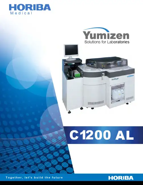
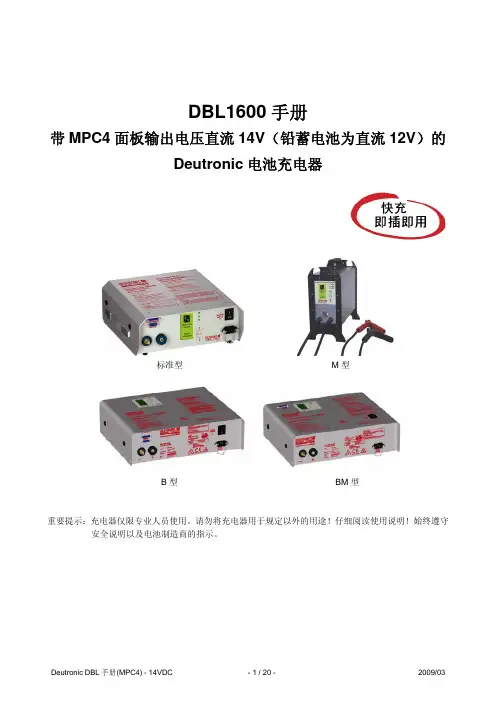
PL1200 Series Concrete BatchingMachineInstruction BookPrefaceProduct instructions as our company delivery to users of an important component of the product, it will be introduced to the characteristics, function, working principle, technical performance, installation and commission , Operation, maintenance, machine fault processing and other aspects, with particular emphasis on the operator about protective measures for safety and environmental protection .To be engaged in the equipment management, operation and repair personnel, this manual is essential read book, it can not only effectively help you to use the equipment and to bring the best economic benefit, But also can avoid the equipment damage and accident.●Please strictly according to the specification of installation and operation!●please be must use our company to provide or recommend equipment parts, to ensure that the the function of the equipment.If the equipment happen series problems, please contact with our company.The instruction with two copies, please be sure to keep a copy , in order to prevent the loss ofaffect your workOur company will be improve the machine step by step,, improve the content without advace notice, please understand this point.Welcome to put forward valuable suggestions, thank you for your cooperation!Contents1.Product Introduction (1)2.Technical Parameter (1)3.Working Principle and Using (1)4. Notice (2)5. Ordering notice (3)6. PL 1200 Series Concrete Batching Machine picture (picture1-picture 13)1 Product IntroductionPL1200 series concrete batching machine is a kind of concrete mixing machinery supporting the use of automatic aggregate batching equipment.The user can use requirements, a reasonable choose its types, specifications, to meet the needs of the construction.The series of ingredients are in accordance with GB / T1017 - 2005"《concrete mixing plant (station )" in batching system technical standard. The machine adopts the electronic balance measurement, and centralized control, digital display, with the measurement high precision speed control performance, ingredients, strong, high reliability.PL1200 series concrete batching machine has many kinds of types are available for users to select: batching machine has two bucket, three buckets and four bucket, a storage hopper capacity is 2. 5m³and 4m³, weigh type divided hopper measurement of belt weigh.2 T technical parameters and Performance Index2.1 Hopper measurement2.2. Belt weighNote: Two-way belt scale batching mixer in batching machine two side, manual reversing ingredients.3 Working Principle and Equipment Using3.1 componentsThe series of ingredients by batching system, measurement system, electric control system is composed of three parts.Batching system consists of a storage hopper, a bracket, the discharge gate, is the completion of the main storage, feeding and frame support ,A large storage hopper hopper for folding, easy to transport to the ground.Measurement system is the equipment key component, by measuring hopper, belt machine and a sensor.Measuring hopper through a pull rod hung on the frame, the total measurement sensor. Through the electric control system of automaticControl of aggregate ( gravel, sand )of aggregate ( gravel, sand) measurement, reaches a set amount, manually or automatically by the weighing hopper bottom and belt conveyer to a lifting hopper mixer.The electric control system is the core part of batching machine, realize the automatic production process, its structure and usingSee " electrical control system installation and operation".The batching machine used ZL30 series loader loading.3.2 Installation of the EquipmentThe operator should first read the instructions carefully, understand the equipment structure and performance, and then to make this machine detailed inspection, operation personnel appropriate training before the operation of induction, a forbidden to operate if not accept the training.After the arrival of the goods at the packing list, inventory parts, technical documentation is complete, check whether the defect.When in installation, Please uses a crane to hoist the entire device to the infrastructure in place, batching machine base adopts embedded steel plate,Batching machine after the adjustment, with the leg plate welding machine with embedded steel plate welding firm. Frame aligning and fixing ,After leaving the metering hopper, hanging, installation of sensors, and is adjusted to the horizontal state, and ensure that the feeding height is appropriate, inspectionCheck all parts are in normal condition.The 3.3 Equipment usingAccording to the" electrical control system installation and operation" requirement, undertake overall debugging, and operation,3.4 Equipment Maintenance3.4.1 Check metering device is in working state before working.3.4.2 Check the screening belt machine is normal, there is no deviation, trauma and foreign body before working.3.4.3 Regularly check all electrical components are firm, grounding is good.3.4.4 Equipment maintenance, should cut off the power, and a hand guard.3.4.5 Periodic lubrication points of each part, regular replacement of gas source two CIS and electric drum gear oil (by gasThe source of the two CIS and electric drum random specification. ).4 Notice:4.1 During the using of the process, you should always pay attention to: whether the deviation of belt machine, such as a deviation, whole road system; whether there is leakage phenomenon, such as leakage, should be repaired in time.4.2 To avoid sand, stone into the belt machine operation of the site.4.3 Please clear the bottom material of Batching machine,and measuring hopper adhesion timely clearance; mixer supporting the use, toThe pit falls the material or product should be the timely removal of material.4.4 Installation of equipment, all piping shall be properly placed, avoid the work being crushed or injury.4.5 batching machine is not a long time, release the sensor rod, so that the sensor is not force, to protect the sensor.4.6 Batching machine transfer site, after loading the sensor bar open, metering bucket is fixed solid can be transported.4.7 Batching machine in the process of use, Please be strictly prohibited in the measuring hopper welding articles, or easy to burn sensor.4.8 After using of Batching machine, please clear the measuring hopper sand, stone unloading hopper, long-term gravity vulnerability will be bad sensor.5 Order Notice:5.1 Please be understand the technical characteristics of equipment and ancillary products.5.2 Please be understand the equipment factory products list.The 5.3 Shipment should be safety first, reliable, the delivery unit should be closed fixed, should not return string.Important NoticePlease read the instructions carefully before use, and strictly follow the instructions about the operation, repair and maintenance, and special attentionTo the following matters:1, Please be strictly implementation of national and local laws and regulations related to safety, Laws, and other.2,Please be regularly add lubrication points of each parts, regular replacement of electric drum gear oil.3, According to the provisions before switching on belt conveyor are examined, with no running partial phenomenon.4, Regularly check the belt wear, if necessary, timely replacement.5 To prevent the occurrence of personal accidents ,prohibited personnel stand machine belt..6 To prevent the occurrence of electrical accident,the electrical equipment should be in strict accordance with the provisions of grounding.。