1500td合成氨工艺粗煤气变换工段第三变换热交换器设计
- 格式:docx
- 大小:4.04 MB
- 文档页数:82
太原理工大学毕业设计(论文)任务书第1页第2页第3页第4页1500t/d合成氨工艺粗煤气变换工段第三变换热交换器设计摘要本次设计在安全前提下,以经济实用为原则,从原始数据开始经工艺计算、机械设计和强度校核三步详尽地阐述了本台换热器的设计过程。
此设计过程有五个部分:绪论,工艺计算,机械设计,强度校核和技术条件的编制。
在绪论中主要叙述了合成氨生产生产中的变换工段在本次这个天脊集团合成氨装置增产节能改造项目中的作用及简单介绍。
控制方案的设计主要是通过对整体设备的综合分析,确定设备的控制方案,达到自动控制目的;工艺计算主要是通过对热量负荷的计算得到换热器的传热面积、初步确定换热器的基本尺寸,为下一步提供依据;机械设计主要任务是在设计条件下,从主体到部件,进行材料和零部件的设计入手,设计合理的结构;强度校核是在满足工艺条件的要求下,对所设计的设备进行强度校核,以便生产可以顺利的进行。
关键词:换热器,工艺计算,机械设计A Design of 1500t / d of crude ammonia process gas shiftconversion section third heat exchangerAbstractThe premise of the design in a safe, economical and practical principle to begin the process calculated from the raw data by the mechanical design and strength check-step detailed exposition of this station heat exchanger design process.This design process has five parts: the preparation of the introduction, process calculations, mechanical design, strength check and technical conditions.Described in the introduction the main role in the production of ammonia production in the second section of this transformation Tianji Group ammonia unit increase in energy-saving projects and brief. Control scheme designed primarily through a comprehensive analysis of the whole device to determine device control solutions, to achieve automatic control purposes; process calculation is mainly through the calculation of the heat load to get the heat exchanger heat transfer area of the heat exchanger initiallyidentified the basic dimensions provide the basis for the next step; mechanical design of the main tasks is under design conditions, from the body to the parts, and materials and components designed to start, well-designed structures; strength check is to meet the requirements under process conditions, equipment designed for the strength check, in order to produce a smooth conduct.Key words: Heat Exchanger;Process calculation;Mechanical Design目录1.绪论彗睬技鹑 (10)1.1变换工段的说明彗睬技鹑 (10)2 工艺设计彗睬技鹑 (12)2.1 确定设计方案彗睬技鹑 (12)2.1.1 选择换热器的类型两流体的温度变化情况 (12)2.1.2 管程安排彗睬技鹑 (12)2.2 确物性数据彗睬技鹑 (12)2.3 估算传热面积彗睬技鹑 (13)2.3.1 热流量(忽略热损失)彗睬技鹑 (13)2.3.2 粗煤气用量(忽略热损失)彗睬技鹑 (13)2.3.3 平均传热温差彗睬技鹑 (13)2.3.4 初算传热面积 (13)2.4 工艺结构尺寸彗睬技鹑 (13)2.4.1 管径和管内流速彗睬技鹑 (13)2.4.2 管程数和传热管数彗睬技鹑 (13)2.4.3 平均传热温差校正及壳程数彗睬技鹑 (13)2.4.4 传热管排列和分程方法彗睬技鹑 (14)2.4.5 壳体直径彗睬技鹑 (14)2.4.6 折流板彗睬技鹑 (14)2.5 换热器核算彗睬技鹑 (15)2.5.1 传热面积校核彗睬技鹑 (15)2.5.2 换热器内内压降核算彗睬技鹑 (17)3 .机械结构设计彗睬技鹑 (19)3.1 设计压力彗睬技鹑 (19)3.2 设计温度彗睬技鹑 (20)3.3 管壁温度彗睬技鹑 (20)3.3.1 符号彗睬技鹑 (20)3.3.2 管程壁温彗睬技鹑 (20)3.3.3 壳程壁温彗睬技鹑 (20)3.4 筒体壁厚彗睬技鹑 (21)3.4.1 筒体选材彗睬技鹑 (21)3.4.2 筒体壁厚计算彗睬技鹑 (21)3.5 管箱厚度彗睬技鹑 (22)3.5.1 管箱选材彗睬技鹑 (22)3.5.2 筒体壁厚计算彗睬技鹑 (22)3.6 管箱法兰彗睬技鹑 (23)3.6.1 材料选择彗睬技鹑 (23)3.6.2 法兰尺寸彗睬技鹑 (23)3.6.3 法兰型式彗睬技鹑 (24)3.6.4 法兰垫片彗睬技鹑 (24)3.7 封头的设计彗睬技鹑 (26)3.7.1 封头选材彗睬技鹑 (26)3.7.2 封头壁厚计算彗睬技鹑 (26)3.7.3 封头尺寸彗睬技鹑 (27)3.8 液压实验彗睬技鹑 (27)3.9 拉杆设计彗睬技鹑 (28)3.9.1 拉杆选材彗睬技鹑 (28)3.9.2 拉杆参数彗睬技鹑 (28)3.9.3 拉杆的布置彗睬技鹑 (28)3.10 管板设计彗睬技鹑 (29)3.10.1 材料的选择彗睬技鹑 (29)3.10.2 管板结构彗睬技鹑 (29)3.10.3 管板布管彗睬技鹑 (29)3.10.4 管孔设计彗睬技鹑 (29)3.10.5 拉杆孔设计彗睬技鹑 (29)3.10.6 管板尺寸彗睬技鹑 (30)3.11 实际布管彗睬技鹑 (31)3.12 换热管设计彗睬技鹑 (31)3.13 接管设计彗睬技鹑 (32)3.13.1 管程接管设计彗睬技鹑 (32)3.13.2 壳程接管设计彗睬技鹑 (32)3.13.3 排气管与降液管设计彗睬技鹑 (33)3.13.4 各接管法兰和垫片的设计彗睬技鹑 (33)3.14 保温层的设计彗睬技鹑 (35)3.15 各接管尺寸设计彗睬技鹑 (35)3.15.1 接管的外伸长度彗睬技鹑 (35)3.15.2壳程接管位置彗睬技鹑 (35)3.15.3管程接管位置彗睬技鹑 (36)3.16 防冲挡板彗睬技鹑 (37)3.16. 1管程彗睬技鹑 (37)3.16.2 壳程彗睬技鹑 (37)3.17折流板与支持板彗睬技鹑 (38)3.17.1材料彗睬技鹑 (38)3.17.2折流板设计彗睬技鹑 (38)3.17.3折流板和支持板管孔彗睬技鹑 (39)3.17.4 折流板布置彗睬技鹑 (39)3.17.5 折流板重量计算彗睬技鹑 (40)3.18 管箱设计彗睬技鹑 (41)3.18.1 管箱结构形式彗睬技鹑 (42)3.18.2 管箱长度彗睬技鹑 (43)3.19 吊耳与顶丝彗睬技鹑 (43)3.19.1 左管箱质量彗睬技鹑 (43)3.19.3 吊耳彗睬技鹑 (44)3.20 支座设计彗睬技鹑 (44)3.20.1 支座所承受的载荷彗睬技鹑 (44)3.20.2 支座尺寸彗睬技鹑 (45)3.20.3 支座材料彗睬技鹑 (46)3.20.4 支座安装尺寸彗睬技鹑 (46)4.焊缝设计彗睬技鹑 (47)5 强度校核彗睬技鹑 (50)彗睬技鹑 .................................................................................................................... 错误!未定义书签。
6 技术条件编制彗睬技鹑 (77)6.1 技术条件说明彗睬技鹑 (77)6.1.1 钢材彗睬技鹑 (77)6.1.2 冷热加工成型彗睬技鹑 (77)6.1.3 焊接条件彗睬技鹑 (78)6.1.4 热处理彗睬技鹑 (78)6.1.5 无损探伤彗睬技鹑 (78)6.2 装配图的技术条件彗睬技鹑 (78)6.3 零件图的技术条件彗睬技鹑 (78)6.3.1 管箱部件图的技术条件编制彗睬技鹑 (78)6.3.2 管板零件图技术条件彗睬技鹑 (79)6.3.3 折流板技术条件彗睬技鹑 (79)结束语彗睬技鹑 (80)参考文献彗睬技鹑 (81)致谢彗睬技鹑 (82)1.绪论1.1变换工段的说明在合成氨工艺生产过程中,变换工艺是一个重要的净化工序,通过变换工序,不尽能制取氢气为合成氨提供原料,而且还减少了CO对氨合成催化剂的毒害。
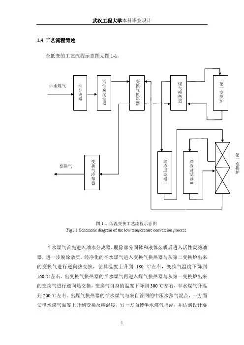
这张工艺物料流程图就是天脊集团合成氨装置增产节能改造项目,针对粗煤气中的CO含量高、水碳比低的特点,对CO变换工艺进行设计与优化。
天脊煤化工集团有限责任公司是我过于20世纪80年代初从国外成套引进技术和设备而兴建的,以煤为原料生产生产硝酸磷复合肥的大型煤化工基地。
其年产30万吨合成氨装置采用MARK-ⅠV型鲁奇加压气化炉气化制成的粗煤气,在一氧化碳变换工序中经过两段钴钼系耐硫催化剂床层进一步提高H2含量,冷却后的变换气进入低温甲醇洗工序除去变换气中的CO2、H2S,除去CO2、H2S的合成气再进入液氮洗工序,脱除CO的同时将N2和H2配比成适当的比例经过合成气压缩机提压后送入托普索100型合成塔进行氨合成。