伊顿电气IZM91_VU断路器型脱扣器说明书
- 格式:pdf
- 大小:3.86 MB
- 文档页数:51
-1-安注意事项:1. 安按产品说明书要求,包括安方式、进线方式、使用条件、铜导线(铜排)截面积(参考值见表11)、使用原厂随机附件等。
2. 额定值是否符合使用要求,包括额定电压、额定电流、额定短路分断能力等等,上下级保护选择要合理。
3. 断路器应清洁,产品上端应无导电物质或其它非导电物质遗落。
4. 断路器安装场所应无爆炸危险、无腐蚀性气体,并应注意防潮、防尘、防震动和避免日晒。
5. 板前接线的断路器可以安装在金属骨架或绝缘板上,板后接线的断路器应安装在绝缘板上。
6. 所有电气联接是否紧固可靠,紧固件联接应根据表14扭矩要求核对。
7. 断路器进行动作特性试验时,应使用经国家有关部门检测合格的专用测试仪器,严禁利用相线直接触碰接地装置的试验方法。
装装装敬告:1. 安装断路器时应按要求,在电弧喷出方向有足够的飞弧距离,并确保相间隔弧板或护罩安装到位,进线端铜排进行了绝缘处理,以防止电弧短路。
2. 安装后应检查断路器与安装板的绝缘电阻。
如有必要对产品进行绝缘测试时,请按以下要求操作:1)用DC 500V兆欧表;2)在断路器处于闭合状态时,对断路器各极分别对地(安装箱金属外壳)间绝缘电阻进行测试;在断路器处于断开状态时,对连接在一起的电源端子与连接在一起的负载端子之间和连接在一起的所有各极带电部件与外壳之间(外壳用金属箔覆盖)分别进行测试;3)绝缘电阻应不小于10M Ω。
3. 因线路短路引起断路器动作后,应更换新的断路器且排除故障后方可投入运行。
4.在使用断路器的情况下,也应保证电气系统接地保护应完好可靠,并且装有剩余电流保护装置。
运行维护:1. 严禁湿手操作断路器,否则可能发生电击事故。
2. 断路器投入运行后,使用单位应作运行记录,并建立相应的管理制度。
3. 断路器因被保护电路发生故障(过载或短路)而分闸时,必须查明原因,排除故障后,才能进行合闸操作。
4. 断路器每六个月进行一次检查,检查时应切断电源,操作手柄使断路器合、分3次,检查机构是否可靠;检查断路器以及断路器与安装板的绝缘电阻,同时清除外壳表面尘-4-注:1. 短路分断能力级别代号:标准型(代号S),较高型(代号H);2. 按操作方式分:手柄直接操作(无代号),电动操作(代号P),转动手柄操作(代号Z);3. 按极数分:三极(代号3),四极(代号4);4. 按用途分:配电保护用(无代号);电机保护用(代号2);5. 四极产品中性极(N)的 型式分为:C型:N极安装过电流脱扣元件,且N极与其它三极一起合分(N极先合 后分);表1 附件名称及代号无附件报警触头分励脱扣器辅助触头欠电压脱扣器分励脱扣器、辅助触头分励脱扣器、欠电压脱扣器二组辅助触头辅助触头、欠电压脱扣器分励脱扣器、报警触头辅助触头、报警触头欠电压脱扣器、报警触头分励脱扣器、辅助触头、报警触头二组辅助触头、报警触头辅助触头、欠电压脱扣器、报警触头300308310320330340350360370318328338348368378附件名称附件代号-5-123456789T 0.3sTR Isd Ii....0.9I R 1.2I RIi (xI n 34681012OFF 2RunOFF0.5 1.0OFFNPTU126080100T (S)9010011012514015016080(A)234568OFF 1.5Isd (xI )2I 4 主要技术参数4.1断路器的额定值见表2。

Eaton SPN84N4WEAXX2HEaton Power Defense SB, Double Narrow, 4000 A, 85 kA, 4-Pole,Drawout, PXR20LSIAM, 84N4WEAXX2HGeneral specificationsEaton Magnum low voltage power circuitbreakerSPN84N4WEAXX2H78668974590516.3 in16.8 in32.4 in177 lbNEMA Compliant CCC Marked SABA ListedCE Marked KEMA CertifiedANSIABS CertifiedLloyd's Register Certified UL ListedCSA CertifiedDNV GL CertifiedProduct Name Catalog NumberUPCProduct Length/Depth Product Height Product Width Product Weight Compliances Certifications4000 AUL 891Double narrow Four-polePower Defense SB UL 891 Double narrow MagnumPXR20DrawoutFour-pole4000 A 600 VAC Drawout 85 kA85 kA 4000 A 4000 A 600 VAC Zone selective interlocking application paperMagnum circuit breakers with Power Xpert Release trip units product aid Selevctive coordination application paper - IA0120000E3Magnum PXR and PD-SB standard and narrow frame UL Certificate of ComplianceMagnum PXR and PD-SB double and double narrow frame UL Certificate of ComplianceAmperage Rating Application FrameNumber of poles Type Application FrameSeriesTrip TypeMounting Method Number of polesRated uninterrupted current (Iu) Voltage rating Mounting Method Interrupt ratingInterrupt ratingAmperage RatingRated uninterrupted current (Iu) Voltage rating Application notes Brochures Catalogs Certification reportsEaton Corporation plc Eaton House30 Pembroke Road Dublin 4, Ireland © 2023 Eaton. All Rights Reserved. Eaton is a registered trademark.All other trademarks areproperty of their respectiveowners./socialmediaMicrosoft Word - Power Xpert Protection Manager Quick Start Guide.docxPower Xpert Release trip unit for Magnum PXR circuit breakers PXR 20/25 user manualMagnum PXR low voltage power circuit breakers user manual Power Xpert Protection Manager x64 22.6 1 Power Xpert Protection Manager x32 22.06 1 Eaton Specification Sheet - SPN84N4WEAXX2H Low voltage circuit breakers guide spec Magnum PXR 20/25 electronic trip units time current curves Safer by design: arc energy reduction techniques Cyber security white paperMolded case and low-voltage power circuit breaker healthManuals and user guidesSoftware, firmware, and applications Specifications and datasheetsTime/current curvesWhite papers。
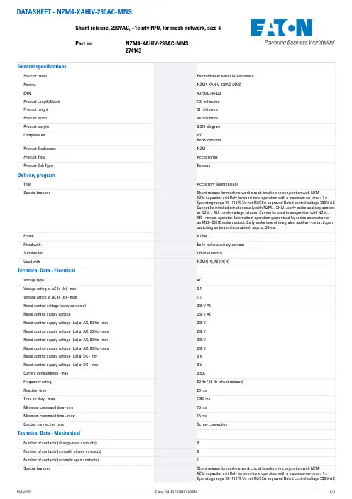
DATASHEET - NZM4-XAHIV-230AC-MNSShunt release, 230VAC, +1early N/O, for mesh network, size 4Part no. NZM4-XAHIV-230AC-MNS 274143
General specifications
Product name Eaton Moeller series NZM releasePart no. NZM4-XAHIV-230AC-MNSEAN 4015082741433Product Length/Depth 107 millimetreProduct height 51 millimetreProduct width 64 millimetreProduct weight 0.218 kilogramCompliances IECRoHS conform
Product Tradename NZMProduct Type AccessoriesProduct Sub Type ReleaseDelivery program
Type Accessory Shunt releaseSpecial features Shunt release for mesh network circuit-breakers in conjunction with NZM-XZM capacitor unit Only for short-time operation with a maximum on-time = 1 sOperating range 10 - 110 % Us not UL/CSA approved Rated control voltage 230 V ACCannot be installed simultaneously with NZM...-XHIV... early-make auxiliary contactor NZM...-XU... undervoltage release. Cannot be used in conjunction with NZM...-XR... remote operator. Intermittent operation guaranteed by series connection ofan M22-(C)K10 make contact. Early-make time of integrated auxiliary contact uponswitching on (manual operation): approx. 90 ms.
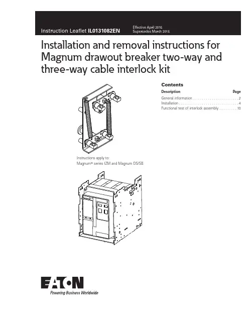
Installation and removal instructions for Magnum drawout breaker two-way and three-way cable interlock kitContentsDescription PageGeneral information . . . . . . . . . . . . . . . . . . . . . . . .2Installation . . . . . . . . . . . . . . . . . . . . . . . . . . . . . . .4Functional test of interlock assembly . . . . . . . . .10Instructions apply to:Magnum T series IZM and Magnum DS/SB2Instruction Leaflet IL0131082ENEffective April 2015Installation and removal instructions for Magnum drawout breaker two-way andthree-way cable interlock kitEATON m WARNING(1) ONLY QUALIFIED ELECTRICAL PERSONNEL SHOULD BE PERMITTED TO WORK ON THE EQUIPMENT.(2) ALWAYS DE-ENERGIZE PRIMARY AND SECONDARY CIRCUITS IF A CIRCUIT BREAKER CANNOT BE REMOVED TO A SAFE WORK LOCATION.(3) DRAWOUT CIRCUIT BREAKERS SHOULD BE LEVERED (RACKED) OUT TO THE DISCONNECT POSITION.(4) ALL CIRCUIT BREAKERS SHOULD BE SWITCHED TO THE OFF POSITION AND MECHANISM SPRINGS DISCHARGED.FAILURE TO FOLLOW THESE WARNINGS FOR ALL PROCEDURESDESCRIBED IN THIS INSTRUCTION LEAFLET COULD RESULT IN DEATH, BODILY INJURY, OR PROPERTY DAMAGE.m WARNINGTHE INSTRUCTIONS CONTAINED IN THIS IL AND ON PRODUCT LABELS HAVE TO BE FOLLOWED. OBSERVE THE FIVE SAFETY RULES: – DISCONNECTING– ENSURE THAT DEVICES CANNOT BE ACCIDENTALLY RESTARTED – VERIFY ISOLATION FROM THE SUPPLY – EARTHING AND SHORT-CIRCUITING– COVERING OR PROVIDING BARRIERS TO ADJACENT LIVE PARTSDISCONNECT THE EQUIPMENT FROM THE SUPPLY. USE ONLY AUTHORIZED SPARE PARTS IN THE REPAIR OF THE EQUIPMENT. THE SPECIFIEDMAINTENANCE INTERVALS AS WELL AS THE INSTRUCTIONS FOR REPAIR AND EXCHANGE MUST BE STRICTLY ADHERED TO PREVENT INJURY TO PERSONNEL AND DAMAGE TO THE SWITCHBOARD.General informationThis information leaflet provides detailed installation instructions for installing and interconnecting one drawout Magnum T breaker to another type of low voltage circuit breaker (LVCB) in any position (see A, B, C in T able 1 and T able 2) for a two-way, three-way Type 31, or three-way Type 33 interlock configuration as shown in Figure 1 . When purchasing kits for a two-way or a three-way interlock configuration setup, additional interlock kits (the types of interlock kits and the other breakers on which they can be installed that are compatible with this kit are listed in T able 3 and T able 4) are required for the other breaker(s) as well as the interconnecting cable kits (one, two, or three are required depending on whether a two-way, three-way Type 31, or three-way Type 33 interlock configuration is desired, respectively) .For two-way and three-way interlock configurations, the mechanical interlock holds one or more of the breakers tripped or open(prevents closure) when some combination of the others are closed . A lever assembly is mounted on each breaker and interfaces with the pole shaft and trip lever . The lever assemblies areinterconnected with cables provided in interconnecting cable kits (listed in T able 5) that are compatible with this interlock kit . Thecable kits, purchased separately, each contain two cables and can be used for any orientation of the breakers according to the installation recommendations in Step 7 .Refer to Figure 2 and Figure 3 for identification of interlock kit and interconnecting cable kit contents, respectively .BC BC ABABCDC DTwo-way cable routingThree-way Type 31cable routingThree-way Type 33cable routingABC DABCDABC DFigure 1. Cable routing for two-way and three-way T ype 31 and T ype 33 interlock configurations T able 1. T wo-way interlock logicBreaker ABreaker BAllowed states or conditions 0010010 = open 1 = closed3Instruction Leaflet IL0131082ENEffective April 2015Installation and removal instructions for Magnum drawout breaker two-way and three-way cable interlock kitEATON T able 2. T wo-way T ype 31 and T ype 33 interlock logicType 33 (six cable)Type 31 (four cable)Breaker Breaker ABCABCAllowed states or conditions 000000100100010101001001———0100 = open 1 = closedT able 3. T wo-way interlock assembly kits for interconnected breakersInterconnected breakerInterlock assembly kit for fixed breakerInterlock assembly kit for drawout breakerNRX Type NF frame IZMX-MIL2C-F16-2IZMX-MIL2C-W16-2NRX Type RF frameIZMX-MIL2C-F40-2IZMX-MIL2C-W40-2Magnum DS T , SB or IZMMCI2W3W3133FX MCI2W3W3133DOT able 4. Three-way interlock assembly kits for interconnected breakersInterconnected breakerInterlock assembly kit for fixed breakerInterlock assembly kit for drawout breakerNRX Type NF frame IZMX-MIL3133C-F16-2IZMX-MIL3133C-W16-2NRX Type RF frame IZMX-MIL3133C-F40-2IZMX-MIL3133C-W40-2Magnum DS, SB or IZM MCI2W3W3133FX MCI2W3W3133DOT able 5. Interconnecting cable kits (two cables per kit) aCable kit lengthCatalogue number1,5 m (5 ft)IZMX-MIL-CAB1520-21,8 m (6 ft)IZMX-MIL-CAB1830-22,4 m (8 ft)IZMX-MIL-CAB2440-23,0 m (10 ft)IZMX-MIL-CAB3050-2a Cable kits are purchased separately as needed.(F)Grease tube3x(B)M6 x 25 mm flathead screw1x(G)Cable bracket1x(H)M6 x 10 mm thread-forming screws2x(E)Interlock assembly1x(D)Drive arm1x(C)Lock washer3x(A)M6 x 12 mm hex bolt 3x Figure 2. Interlock kit part identification, includes parts to install on a single drawout Magnum breaker and cassette (does not include cables)4Instruction Leaflet IL0131082ENEffective April 2015Installation and removal instructions for Magnum drawout breaker two-way andthree-way cable interlock kitEATON Figure 3. Interconnecting cable kit part identification (includes cables)Installation of two-way cable interlockRequired tools• 10 mm hex socket • 10 mm open-end wrench • 11/16-inch open-end wrench • 3/8-inch open-end wrench (2)• 4 mm Allen wrench • Drive extension • Pliers • Ratchet•Measuring instrument, in mmBefore proceeding with the following steps, ensure that all breakers are in the OPEN and DISCHARGED position .Step 1Remove the four hex-head captive bolts (six for 4-pole breaker) holding the cover in place as shown in Figure 4 . Pull down on the charginghandle (approximately 45 degrees) and remove the front cover .Figure 4. Details for Step 1Step 2Remove drive arm window as shown in Figure 5 . Either use a utility knife to cut the window from the cover, or use a punch and a small hammer to carefully punch out the window . Once the window is removed, use a small file to remove any burrs that remain . Make certain that all pieces and/or particles are cleaned up and removed before proceeding .Figure 5. Details for Step 25Instruction Leaflet IL0131082ENEffective April 2015Installation and removal instructions for Magnum drawout breaker two-way and three-way cable interlock kitEATON Step 3Install the drive arm (D) to the end of the pole shaft using an M6 x 25 mm flat-head screw (B) . Apply Loctite T Blue 242 to ensure that the screw cannot loosen during operation . The drive arm should be oriented as shown in Figure 6 . Torque to 7,3–9,6 N∙m (65–85 in-lb) .Pole shaft(B)(D)End of pole shaftFigure 6. Details for Step 3 and 4Step 4Reinstall the front cover using the four hex-head captive bolts (six for 4-pole breaker) removed in Step 1 .Step 5Fasten the interlock assembly (E) to the drawout cassette’s right-side sheet using three M6 x 12 mm hex bolts (A) and three lock washers (C) as shown in Figure 7 . Torque to 4,5–5,6 N∙m (40–50 in-lb) .Cassette right-side sheet(E)(A)(C)Figure 7. Details for Step 5Step 6Fasten cable bracket (G) to the drawout cassette’s right-side sheetjust below the interlock assembly (mounted in Step 5) using two M6 x 10 mm thread-forming screws (H) as shown in Figure 8 . Torque to 7,3–9,6 N∙m (65–85 in-lb) . Ensure the trip paddle is behind (on the same side as the back of the breaker) the trip lever as shown in Figure 9 .(H)(G)Cassette right-side sheetFigure 8. Details for Step 6Trip paddleTrip leverFollower armDrive armFigure 9. Details for Step 66Instruction Leaflet IL0131082ENEffective April 2015Installation and removal instructions for Magnum drawout breaker two-way andthree-way cable interlock kitEATON Step 7This step offers cable routing and installation procedures . Make sure that cables move freely in their cable housings before installation . When attaching cables to swivel fittings, ensure that both ends of the cable are connected to push swivel fittings or both ends of the cable are connected to pull swivel fittings (refer to Figure 11) . For example, a cable connected to the drive lever pull swivel fitting on Breaker A must connect to the driven level pull swivel fitting on Breaker B .ATTENTIONFIGURE 10 SHOWS THE TYPICAL CABLE ROUTING FOR TWO-WAY AND THREE-WAY TYPE 31 AND TYPE 33 INTERLOCK CONFIGURATIONS.NOTICE THAT DEPENDING ON THE POSITION OF THE BREAKER WITHIN THE INTERLOCK CONFIGURATION, THE CABLES WILL BE ATTACHED IN DIFFERENT LOCATIONS. THE CABLE MOUNTING ON BOTH SWIVEL FITTINGS OF THE DRIVE AND DRIVEN LEVERS ARE DESCRIBED BELOW. TABLE 6 SHOWS THE TWO-WAY INTERLOCK LOGIC DEPENDING ON POSITION. TABLE 7 SHOWS THE THREE-WAY TYPE 31 AND TYPE 33 INTERLOCK LOGIC DEPENDING ON POSITION.BC BC ABABC DCDTwo-way cable routingThree-way Type 31cable routingThree-way Type 33cable routingABCDABC DABCDFigure 10. Cable routing for interlock configurationsT able 6. T wo-way interlock logicBreaker ABreaker BAllowed states or conditions 0010010 = open 1 = closedT able 7. Three-way T ype 31 and T ype 33 interlock logicType 33 (six cable)Type 31 (four cable)Breaker Breaker ABCABCAllowed states or conditions 000000100100010101001001———0100 = open 1 = closed7Instruction Leaflet IL0131082ENEffective April 2015Installation and removal instructions for Magnum drawout breaker two-way and three-way cable interlock kitEATON Installation recommendations• 102 mm (4 in) minimum allowable cable housing bend radius •Use plastic wire ties / clamps to attach cable housing to structure after installation and adjustment • Do not compress cable housing •Recheck to ensure cables move freelyDriven lever pull swivel fittingDriven lever push swivel fittingDriven leverDrive lever pull swivel fittingDrive lever push swivel fitting GapDrive lever Figure 11. Push and pull swivel fitting identificationStep 8This step describes how to first attach the drive (short rod) end of a cable to its interlock assembly and cable bracket . See Figure 12 .To attach the drive (short) end of the cable to the drive lever pull swivel fitting (refer to Figure 11), follow the directions below .1. Remove the upper nut, compression spring, and 38,1 mm(1,5 in) tube spacer from end of rod of cable assembly .2. Slide rubber boot toward tip of rod .3. Unthread outer bulkhead nut, and slide nut and lock washertoward tip .4. Insert threaded end of rod into swivel fitting .5. Slide smaller diameter portion of bulkhead fitting into cablebracket slot .6. Raise the cable assembly until threaded portion of bulkheadfitting enters slotted hole in cable bracket (threads show above bracket) .7. Bring bulkhead washer and nut down to threads andhand tighten .8. Adjust two bulkhead nuts to approximately center the bulkheadfitting on the cable mounting bracket . 9. Hand tighten the bulkhead nuts at this time .10. Slide rubber boot back into place over end of bulkhead fitting .11. Replace 38,1 mm (1,5 in) tube spacer, compression spring, andupper nut on end of rod .12. Lower nuts should be shouldered against end of thread andupper nut tightened against tube spacer .13. Hold lower nuts and torque upper nut to 3,3–4,5 N∙m (30–40 in-lb) .To attach the drive (short rod) end of a cable to the drive leverpush swivel fitting of the drive lever (refer to Figure 11), follow the directions below (see Figure 12) .1. Remove upper nut from end of rod of cable assembly .2. Slide rubber boot toward tip of rod .3. Unthread outer bulkhead nut and slide nut and lock washertoward tip .4. Insert threaded end of rod with 38,1 mm (1,5 in) tube spacerinto swivel fitting, ensuring that the compression spring remains between the lower nuts and the swivel .5. Slide smaller diameter portion of bulkhead fitting into cablebracket slot .6. Raise the cable assembly until threaded portion of bulkheadfitting enters slotted hole in cable bracket (threads show above bracket) .7. Bring bulkhead washer and nut down to threads andhand tighten .8. Adjust two bulkhead nuts to approximately center the bulkheadfitting on the cable mounting bracket . 9. Hand tighten the bulkhead nuts at this time .10. Slide rubber boot back into place over end of bulkhead fitting .11. Lower nuts should be shouldered against end of thread andupper nut tightened against tube spacer .12. Hold lower nuts and torque upper nut to 3,3–4,5 N∙m(30–40 in-lb) .8Instruction Leaflet IL0131082ENEffective April 2015Installation and removal instructions for Magnum drawout breaker two-way andthree-way cable interlock kitEATON Figure 12. Details for Step 8: Cable assembly drive (short rod) end mounting component identification, mounting cable assembly in cable bracket, and cable rod attachment to drive arm9Instruction Leaflet IL0131082ENEffective April 2015Installation and removal instructions for Magnum drawout breaker two-way and three-way cable interlock kitEATON Step 9This step describes how to attach the driven (long rod) end of a cable attached to an interlock assembly on another breaker to the cable bracket and interlock assembly on this Magnum breaker . Refer to Figure 10 and Figure 11 for cable routing and correct swivel fittings to which the cables are connected .The driven (long rod) end of the cable is attached to the correspond-ing push or pull swivel fitting on the driven lever on this cable interlock assembly similarly to Step 8 except the driven end does not utilize a compression spring between the swivel and nut .Remove and discard the 22,2 mm (0,875 in) cable tube spacer (K) on the rod end of the cable assembly (I) and replace it with the 38,1 mm (1,5 in) cable tube spacer (J) . Install the cable as shown in Figure 13 and Figure 14 .Upper nuts Swivel fittings 38,1 mm (1,5 in) cable tube spacer Driven end (long end)Lower nuts Rubber bootDriven end cable bracketsOuter bulkhead nutBulkhead nutFigure 13. Details for Step 9Step 10This step describes how to adjust the cables to ensure proper functionality of the cable interlock setup . Cable adjustments are made with the large bulkhead nuts ONL Y and with all breakers OPEN . Nuts on the rod ends should not be moved .Begin by adjusting or verifying that all bulkhead fittings areapproximately centered on the cable mounting brackets (center of threaded section of bulkhead), allowing for room for adjustment in either direction . Hand tighten the nuts at this time .Perform initial adjustments on the driven (long rod) end of cable . There should be a small (0–5 mm) clearance between the upper nut and the face of the driven lever pull swivel on which it pulls and between the lower nuts and the face of the driven lever push swivel on which it pushes as shown in Figure 14 .If there is too much clearance , adjust both bulkhead nuts to retract the cable housing (move threaded portion down) .If there is no clearance , advance the cable housing in the same manner (move threaded portion up) .If additional adjustment length is needed, the bulkhead nuts on the other end of cable can be used .When the proper clearance is attained on the driven end, torque the cable bulkhead nuts on both ends to 11–13 N∙m (100–120 in-lb) without moving the bulkhead fittings .After the driven end has been adjusted and the bulkhead nuts have been tightened, perform adjustments on the drive (short rod) end of the cable . Adjust the bulkhead nuts up (move threaded portion down) such that the gap between the drive lever and the interlock assembly base shown on Figure 11 is less than 4 mm .When the gap is less than 4 mm, torque the cable bulkhead nuts on both ends to 11–13 N∙m (100–120 in-lb) .Between 0 and 5 mm after adjusting cableBetween 0 and 5 mm after adjusting cableTighten these nuts before mounting driven endAdjustment nutsAdjustment nuts Cable bracketLong rodDrive lever Short rod Drive endFigure 14. Details for Steps 9 and 1010Instruction Leaflet IL0131082ENEffective April 2015Installation and removal instructions for Magnum drawout breaker two-way andthree-way cable interlock kitEATON Functional test of interlock assemblyBegin test sequence with all breakers OPEN .T wo-way interlock configuration functional testCheck 1: CHARGE and CLOSE Breaker A• Verify that Breaker A closed using the OPEN/CLOSED indication •Inspect the driven lever on Breaker B . Check that it rotated from its initial position•CHARGE and attempt to CLOSE Breaker B . It should not respond to CLOSE attempt (no noise, spring discharge, or contact motion)•If Breaker B responds to the CLOSE attempt, then additional adjustments may be required at the cable mounting brackets (refer to Steps 8, 9, and 10)Check 2: Open Breaker A• The interlock should release•CLOSE Breaker B (if already CHARGED) . Verify that it closes using the OPEN/CLOSED indication• Breaker A should remain in the OPEN position •OPEN Breaker BRepeat Checks 1 and 2 above on Breaker B , using Breaker B as Breaker A and Breaker A as Breaker B•Verify proper operation on both breakersThe mechanical interlock is now properly installed and adjusted for the two-way interlock configuration . Use a light amount of supplied lubricant (F) if any interlock parts are sticky or do not fully reset . This is only recommended if needed .T ype 31—Four-cable interlock assembly testRefer to T able 2 for logic details .• CHARGE and CLOSE Breaker A•CHARGE and attempt to CLOSE Breaker B . It should not respond to CLOSE attempt (no noise, spring discharge, or contact motion)•CHARGE and CLOSE Breaker C . Verify that Breaker C closes using the OPEN/CLOSED indication and that Breaker A remains CLOSED•CHARGE and attempt to CLOSE Breaker B again . It should still not respond to CLOSE attempt (no noise, spring discharge, or contact motion)•OPEN Breaker A . Verify that Breaker C is still CLOSED . CHARGE and attempt to CLOSE Breaker B . It should still not respond to CLOSE attempt (no noise, spring discharge, or contact motion)• OPEN Breaker C . All breakers should now be OPEN•CHARGE and CLOSE Breaker B . CHARGE and attempt to CLOSE Breakers A and C . Verify that they do not respond to CLOSE attempt (no noise, spring discharge, or contact motion)The mechanical interlock is now properly installed and adjusted for the three-way Type 31 interlock configuration . Use a light amount of supplied lubricant (F) if any interlock parts are sticky or do not fully reset . This is only recommended if needed .T ype 33—Six-cable interlock assembly testRefer to T able 2 for logic details .• CHARGE and CLOSE Breaker A•CHARGE and attempt to CLOSE Breakers B and C . Verify that neither breaker responds to CLOSE attempt (no noise, spring discharge, or contact motion)•OPEN Breaker A . The interlock should release•Repeat above test on Breakers B using B for A , C for B , and A for C and Breaker C using C for A , A for B , and B for CThe mechanical interlock is now properly installed and adjusted for the three-way Type 33 interlock configuration . Use a light amount of supplied lubricant (F) if any interlock parts are sticky or do not fully reset . This is only recommended if needed .Figure 15. Functional test gap checks11Instruction Leaflet IL0131082ENEffective April 2015Installation and removal instructions for Magnum drawout breaker two-way and three-way cable interlock kitEATON Eaton1000 Eaton Boulevard Cleveland, OH 44122 United StatesEaton .com© 2015 EatonAll Rights ReservedPrinted in USAPublication No . IL0131082EN / Z16558 Part Number: IL0131082ENH02April 2015Eaton is a registered trademark.All other trademarks are propertyof their respective owners. Installation and removal instructions for Magnum drawout breaker two-way andthree-way cable interlock kitInstruction Leaflet IL0131082ENEffective April 2015Disclaimer of warranties and limitationof liabilityThe information, recommendations, descriptions, and safety notations in this document are based on Eaton’s experience and judgment, and may not cover all contingencies . If further information is required, an Eaton sales office should be consulted .Sale of the product shown in this literature is subject to the terms and conditions outlined in appropriate Eaton selling policies or other contractual agreement between Eaton and the purchaser .THERE ARE NO UNDERSTANDINGS, AGREEMENTS, WARRANTIES, EXPRESSED OR IMPLIED, INCLUDING WARRANTIES OF FITNESS FOR A PARTICULAR PURPOSE OR MERCHANTABILITY, OTHER THAN THOSE SPECIFICALL Y SET OUT IN ANY EXISTING CONTRACT BETWEEN THE PARTIES . ANY SUCH CONTRACT STATES THE ENTIRE OBLIGATION OF EATON . THE CONTENTS OF THIS DOCUMENT SHALL NOT BECOME PART OF OR MODIFY ANY CONTRACT BETWEEN THE PARTIES .In no event will Eaton be responsible to the purchaser or user in contract, in tort (including negligence), strict liability or otherwisefor any special, indirect, incidental or consequential damage or loss whatsoever, including but not limited to damage or loss of use of equipment, plant or power system, cost of capital, loss of power, additional expenses in the use of existing power facilities, or claims against the purchaser or user by its customers resulting fromthe use of the information, recommendations and description contained herein .The information contained in this manual is subject to change without notice .。
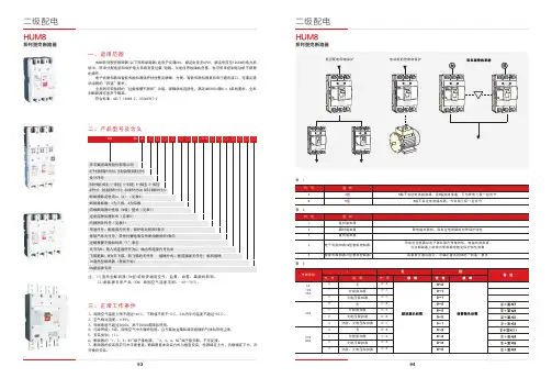
9493表 1表 2表 3二、产品型号及含义系列塑壳断路器1、周围空气温度上限不超过+40℃,下限值不低于-5℃,24h内平均温度不超过+35℃。
2、空气相对湿度:≤95%。
3、海拔高度不超过2000m,高于2000m需降容使用。
4、污染等级:3 级。
周围空气中无爆炸危险、且无腐蚀金属和破坏绝缘的气体和导电尘埃。
5、安装类别:III。
6、断路器的“1,3,5,N1” 端子接电源,“2,4,6,N2” 端子接负载,不可反接。
7、断路器的安装面应与水平面垂直。
断路器基本安装方式为垂直安装,电源端在上方,负载端在下方,亦可横向安装。
H UM8系列塑壳断路器(以下简称断路器)适用于交流 50Hz,额定电压至690V,额定电流至1250A的电力系统中,用来分配电能和保护电力系统免受过载 、短路、欠电压等故障的危害,也可用来控制电动机不频繁的操作。
电子式脱扣器和智能式脱扣器保护特性整定精确、方便。
智能式脱扣器具有串行通讯接口,可满足通讯组网的“四遥”要求。
全系列可带独特的“过载报警不脱扣”功能,保障供电连续性,满足GB 50054第6.3.6条的要求。
全系列断路器可适用于隔离。
符 合标准:GB/T 14048.2、IEC 60947-2注:(1)湿热型断路器(TH型)能耐受潮湿空气、盐雾、油雾、霉菌的影响。
(2)新能源专用产品(EN)周围空气湿度范围:-40~70℃。
系列塑壳断路器一、适用范围三、正常工作条件系列塑壳断路器系列塑壳断路器9695续表 4四、主要技术性能指标8、断路器在不同环境下的降容系数,见下表a 表 (a)()注:以各种环境温度条件下,实测断路器进出线端温度达到110℃为基准。
海拔超过适用工作环境的2000m,断路器的电气性能可参照下表修正,海报降容系数表,见下表(b)表 (b)表 4*飞弧距离为零的需在订货时注明。
10,16,20,25,32,40,50,6316,25,32,40,50,63,80,100100,125,150,160,175,200,225,2504333433310/5-85/85125/12510/5-125/125200/20010/5-85/85125/12510/5-125/125200/2008*飞弧距离为零的需在订货时注明。

断路器瞬时脱扣作业指导书摘要:I.引言A.介绍断路器瞬时脱扣的概念B.提出现场操作的具体流程II.准备工作A.断路器的检查B.工具和材料的准备III.操作步骤A.断路器的开启B.瞬时脱扣的操作C.断路器的关闭IV.安全注意事项A.操作过程中的安全措施B.防止误操作的方法V.总结A.回顾操作流程B.强调安全注意事项正文:I.引言断路器瞬时脱扣是指在电路发生短路或过载时,断路器能够迅速切断电路,保护电器设备和人身安全。
瞬时脱扣操作是电力系统中常见的操作之一,对于电力系统的安全运行至关重要。
本文将详细介绍断路器瞬时脱扣的操作流程。
II.准备工作在进行断路器瞬时脱扣操作前,必须对断路器进行检查,确保其处于正常状态。
同时,需要准备相应的工具和材料,包括操作杆、手套、眼镜等。
III.操作步骤A.断路器的开启首先,需要使用操作杆打开断路器,将其切换到工作状态。
在操作过程中,应注意操作杆的位置和方向,避免误操作。
B.瞬时脱扣的操作在断路器处于工作状态时,需要按下瞬时脱扣按钮。
瞬时脱扣按钮通常位于断路器的操作面板上,操作时应注意不要误触其他按钮。
C.断路器的关闭在完成瞬时脱扣操作后,需要将断路器切换回关闭状态,以确保电路不会误通。
在操作过程中,应注意操作杆的位置和方向,避免误操作。
IV.安全注意事项A.操作过程中的安全措施在进行断路器瞬时脱扣操作时,应佩戴手套和眼镜,避免因电弧和火花造成伤害。
同时,应注意操作杆的位置和方向,避免误操作。
B.防止误操作的方法为了防止误操作,应在操作前仔细阅读操作指导书,了解操作流程和注意事项。
同时,应在操作过程中保持专注,避免分心。
V.总结断路器瞬时脱扣操作是电力系统中常见的操作之一,对于电力系统的安全运行至关重要。
基本分断能力(B)标准分断能力(N)高分断能力(H)额定数据设定范围高分断能力(H)额定电流=额定持续电流过载保护短路保护延时A A A AI n I u I r I sd瞬时I iI IIZM...3-...额定数据设定范围基本分断能力(B)标准分断能力(N)额定数据设定范围基本分断能力(B)标准分断能力(N)高分断能力(H)额定数据设定范围额定电流=额定持续电流过载保护短路保护瞬时延时III n I u I r I sd I iAAA高分断能力(H)4000500063001600-40002000-50002520-63005000-480006250-500007875-500004000500063001600-40002000-50002520-630050000V,选择性保护/电动机保护D,数字型(含图形显示)IZM...3-4...高分断能力(H)基本分断能力(B)标准分断能力(N)D 数字型谐波测量:1) I,U,P,cosφ,ω,峰值等2) 2套独立的波形存储(电流,电压)3) 对29次以下的谐波均可分析如需应用全部功能,则须订购 24 V DC 电源;如无额外电源,则数据不能存储电流和设置参数,在以下条件下才能显示:负载电流>80A (IZM...1...,IZM...2...);负载电流>200A (IZM...3...)tg: 0.1-5s Ig: (IZM...1...,IZM...2...): 100, 300, 600, 900, 1200A Ig: (IZM...3...): 400, 600, 800, 1000, 1200A通讯套件含通讯模块和断路器传感器断路器53断路器断路器断路器断路器断路器断路器断路器型号订货号型号订货号型号订货号型号订货号保护单元功能保护单元功能IZM...1-A...IZM...1-V...IZM...1-U...IZM...1-D...630 800 1000 1250 16005040 6400 8000 10000 1280050 65 50 65 50 65 50 6550 65630 800 1000 1250160012600 16000 20000 25000 3200050 65 50 65 50 6550 6550 6540 52 40 52 40 52 40 52 40 5250 65 50 65 50 65 50 65 50 6540 52 40 52 40 52 40 52 40 5250 65 50 65 50 65 50 6550 65额定电流型号型号选择性保护:带配电保护单元(A)的进线断路器带全能保护单元(U)的进线断路器带数字式保护单元(D)的进线断路器带选择性保护单元(V)的进线断路器额定持续电流选择性保护:短路瞬时保护设置值额定电流额定持续电流短路瞬时保护设置值注T: 完全选择性利用断路器之间的选择性保护功能,可以单独有出线断路器2分闸。

低压配电产品型号说明低压配电产品型号说明目录低压配电与控制产品低压配电产品型号说明产品图配电产品 . . . . . . . . . . . . . . . . . . . . . . . . . . . . . . . . . . . . . . . . . . . . . . . . . . . . . . . . . . . . . . . . . . . . . . .2工控产品 . . . . . . . . . . . . . . . . . . . . . . . . . . . . . . . . . . . . . . . . . . . . . . . . . . . . . . . . . . . . . . . . . . . . . . .2低压配电产品空气断路器 . . . . . . . . . . . . . . . . . . . . . . . . . . . . . . . . . . . . . . . . . . . . . . . . . . . . . . . . . . . . . . . . . . . . .4塑壳断路器 . . . . . . . . . . . . . . . . . . . . . . . . . . . . . . . . . . . . . . . . . . . . . . . . . . . . . . . . . . . . . . . . . . . . .8低压终端配电产品. . . . . . . . . . . . . . . . . . . . . . . . . . . . . . . . . . . . . . . . . . . . . . . . . . . . . . . . . . . . . . .12低压控制产品电动机起动和保护产品 . . . . . . . . . . . . . . . . . . . . . . . . . . . . . . . . . . . . . . . . . . . . . . . . . . . . . . . . . . .26驱动产品 . . . . . . . . . . . . . . . . . . . . . . . . . . . . . . . . . . . . . . . . . . . . . . . . . . . . . . . . . . . . . . . . . . . . . .31主令控制产品 . . . . . . . . . . . . . . . . . . . . . . . . . . . . . . . . . . . . . . . . . . . . . . . . . . . . . . . . . . . . . . . . . .36工业自动化产品 . . . . . . . . . . . . . . . . . . . . . . . . . . . . . . . . . . . . . . . . . . . . . . . . . . . . . . . . . . . . . . . .421低压配电产品型号说明产品图低压配电产品低压工控产品空气断路器IZM9变频器软起动器M22按钮和指示灯空气断路器IZM6控制继电器easyE4SmartWire-DT智能总线系统限位开关LSPower Defense 塑壳断路器Easy安全控制继电器ES4PXC300可编程控制器2低压配电产品型号说明产品图塑壳断路器BZMX触摸屏/触摸屏-PLCXN300远程I/O模块信号塔SL微型断路器Xpole/FAZ电动机保护开关电动机起动和保护产品继电器微型断路器Xpole-xD-Line接触器电动机起动和保护产品双电源自动转换开关脚踏手拍开关FAK凸轮开关T和主令开关P接触器式继电器DIL ET3注:具体技术参数及详细选型请参见低压产品样本。
Eaton MPN6404LEAXX2QEaton Magnum low voltage power circuit breaker, Magnum PXR,Double narrow frame, 4000 A (NNABCABC), 65 kA, Four-pole,Drawout horizontal mounting, PXR25 LSIAM trip unitGeneral specificationsEaton Magnum low voltage power circuitbreakerMPN6404LEAXX2Q78668959941616.3 in16.8 in32.4 in177 lbCE Marked SABA Listed NEMA Compliant CCC Marked KEMA CertifiedCSA CertifiedANSILloyd's Register Certified UL ListedDNV GL CertifiedABS CertifiedProduct Name Catalog NumberUPCProduct Length/Depth Product Height Product Width Product Weight Compliances CertificationsDouble narrow Four-pole Magnum PXRDouble narrow Magnum PXR25 LSI ARMSFour-pole4000 A65 kAIC65 kAIC4000 AZone selective interlocking application paper Magnum circuit breakers with Power Xpert Release trip units product aid Selevctive coordination application paper - IA0120000E3Magnum PXR and PD-SB standard and narrow frame UL Certificate of ComplianceMagnum PXR and PD-SB double and double narrow frame UL Certificate of ComplianceMagnum PXR low voltage power circuit breakers user manual Power Xpert Release trip unit for Magnum PXR circuit breakers PXR 20/25 user manualMicrosoft Word - Power Xpert Protection Manager Quick StartFrame Number of poles TypeFrame Series Trip TypeNumber of poles Rated uninterrupted current (Iu)Interrupt rating Interrupt rating Rated uninterrupted current (Iu)Application notesBrochuresCatalogsCertification reportsManuals and user guidesEaton Corporation plc Eaton House30 Pembroke Road Dublin 4, Ireland © 2023 Eaton. All Rights Reserved. Eaton is a registered trademark.All other trademarks areproperty of their respectiveowners./socialmediaGuide.docxPower Xpert Protection Manager x32 22.06 1 Power Xpert Protection Manager x64 22.6 1 Eaton Specification Sheet - MPN6404LEAXX2Q Low voltage circuit breakers guide spec Magnum PXR 20/25 electronic trip units time current curves Molded case and low-voltage power circuit breaker health Cyber security white paperSafer by design: arc energy reduction techniquesSoftware, firmware, and applications Specifications and datasheetsTime/current curvesWhite papers。
600 A U-OP visible break connector system operation instructionsDISCLAIMER OF WARRANTIES AND LIMITATION OF LIABILITYThe information, recommendations, descriptions and safety notations in this document are based on Eaton Corporation’s (“Eaton”) experience and judgment and may not cover all contingencies. If further information is required, an Eaton sales office should be consulted. Sale of the product shown in this literature is subject to the terms and conditions outlined in appropriate Eaton selling policies or other contractual agreement between Eaton and the purchaser.THERE ARE NO UNDERSTANDINGS, AGREEMENTS, WARRANTIES, EXPRESSED OR IMPLIED, INCLUDING WARRANTIES OF FITNESS FOR A PARTICULAR PURPOSE OR MERCHANTABILITY, OTHER THAN THOSE SPECIFICALLY SET OUT IN ANY EXISTING CONTRACT BETWEEN THE PARTIES. ANY SUCH CONTRACT STATES THE ENTIRE OBLIGATION OF EATON. THE CONTENTS OF THIS DOCUMENT SHALL NOT BECOME PART OF OR MODIFY ANY CONTRACT BETWEEN THE PARTIES. In no event will Eaton be responsible to the purchaser or user in contract, in tort (including negligence), strict liability or other-wise for any special, indirect, incidental or consequential damage or loss whatsoever, including but not limited to damage or loss of use of equipment, plant or power system, cost of capital, loss of power, additional expenses in the use of existing power facilities, or claims against the purchaser or user by its customers resulting from the use of the information, recom-mendations and descriptions contained herein. The information contained in this manual is subject to change without notice.ii600 A U-OP VISIBLE BREAK CONNECTOR SYSTEM OPERATION INSTRUCTIONS MN650022EN March 2016ContentsSAFETY INFORMATIONSafety information (iv)PRODUCT INFORMATIONIntroduction (1)Acceptance and initial inspection (1)Handling and storage (1)Standards (1)Description of operation (1)INSTALLATION PROCEDUREEquipment required (2)Isolating and grounding a cable requiring repair (3)Reconnecting the circuit from the cable to the apparatus bushing (5)iii 600 A U-OP VISIBLE BREAK CONNECTOR SYSTEM OPERATION INSTRUCTIONS MN650022EN March 2016Eaton meets or exceeds all applicable industry standards relating to product safety in its Cooper Power™ series products. We actively promote safe practices in the use and maintenance of our products through our service literature, instructional training programs, and the continuous efforts of all Eaton employees involved in product design, manufacture, marketing, and service.We strongly urge that you always follow all locally approved safety procedures and safety instructions when working around high voltage lines and equipment, and support our “Safety For Life” mission.iv 600 A U-OP VISIBLE BREAK CONNECTOR SYSTEM OPERATION INSTRUCTIONS MN650022EN March 2016S1S2Figure 2. One-line diagram of a three-phase cable connected to a three-phase switch on either end.1600 A U-OP VISIBLE BREAK CONNECTOR SYSTEM OPERATION INSTRUCTIONS MN650022EN March 2016Figure 4. Open switch at both ends of cable.2600 A U-OP VISIBLE BREAK CONNECTOR SYSTEM OPERATION INSTRUCTIONS MN650022EN March 2016Isolating and grounding a cable requiring repair1. De-energize cablesA. Open switches at both ends of cable to be isolated.Refer to Figure 4.B. Determine that there is adequate working roomaround the terminators for parking the groundedstandoff bushings.C. Determine that there is adequate working room forhandling clampstick around apparatus cabinet.D. Place insulating rubber blanket on the grounddirectly in front of terminators.E. Inspect and test all operating equipment forserviceability.F. Connect grounding elbows to system ground.G. Connect ground leads of protective caps to systemground.H. Connect ground leads of grounded standoffbushings to system ground.2. Determine that cables are de-energizedA. Remove 200 A protective cap or arrester fromT-OP II terminators using clampstick and set aside ina clean, protected area.B. Insert test probe into 200 A interfaces usingclampstick.C. Test for voltage by using voltage detector designedfor terminators. Remove probe after testing.3. Provide a visible groundA. Close grounding elbows into T-OP II 200 A interfaceusing a clampstick. Refer to Figure 5.4. Provide a visible breakA. Clean and lubricate grounded standoff bushing.B. Mount grounded standoff bushing in the apparatusparking pocket using a clampstick. Do not tighteneyebolt–leave grounded standoff bushing loose inparking stand. Refer to Figure 6.C. Grasp U-OP operating handle with clampstick, butdo not pull handle completely into clampstick.Figure 6. Mount grounded standoff bushing.High Voltage. Do not proceed until cable is de-energized.Failure to company may result in death, serious personalinjury and equipment damage.High Voltage. Ground all three phases (Steps 2 and3) before proceeding. Failure to comply may result inserouis personal injury and equipment damage.3 600 A U-OP VISIBLE BREAK CONNECTOR SYSTEM OPERATION INSTRUCTIONS MN650022EN March 20168.to Figure 9.J. Attach U-OP protective cap’s drain wire to systemground.Figure 9. Install U-OP protective cap on exposed bushing.Figure 10. Checking if the U connector is fully seated.INDENTATION IN HOLD-DOWN STUDFigure 7. Disengage U-OP operating shaft.Figure 8. Reorient the U connector.4600 A U-OP VISIBLE BREAK CONNECTOR SYSTEM OPERATION INSTRUCTIONS MN650022EN March 2016Figure 13. Install protective cap or arrester.Figure 12. Reorient the U connector.Figure 11. Disengage operating shaft from mating stud.5600 A U-OP VISIBLE BREAK CONNECTOR SYSTEM OPERATION INSTRUCTIONS MN650022EN March 2016This page intentionally left blank.6600 A U-OP VISIBLE BREAK CONNECTOR SYSTEM OPERATION INSTRUCTIONS MN650022EN March 2016This page intentionally left blank.7 600 A U-OP VISIBLE BREAK CONNECTOR SYSTEM OPERATION INSTRUCTIONS MN650022EN March 2016Eaton1000 Eaton Boulevard Cleveland, OH 44122United StatesEaton’s Cooper Power Systems Division2300 Badger Drive Waukesha, WI 53188United States/cooperpowerseries© 2016 EatonAll Rights ReservedPrinted in USAPublication No. MN650022EN Rev 00 (Replaces S600141 Rev. 00)Eaton is a registered trademark.All trademarks are propertyof their respective owners.For Eaton's Cooper Power series productinformation call 1-877-277-4636 or visit:/cooperpowerseries.。