第5章多协议标记交换MPLS
- 格式:ppt
- 大小:375.50 KB
- 文档页数:23


通信网络规划与建设指南 第1章 引言 ..................................................................................................................................... 3 1.1 通信网络概述 ................................................................................................................... 3 1.2 网络规划与建设的重要性 ............................................................................................... 4 1.3 网络规划与建设的基本原则 ........................................................................................... 4 第2章 网络规划基础 ..................................................................................................................... 4 2.1 网络规划的概念与目标 ................................................................................................... 5 2.2 网络规划的主要内容 ....................................................................................................... 5 2.3 网络规划的基本流程 ....................................................................................................... 5 第3章 网络需求分析 ..................................................................................................................... 6 3.1 需求收集与分析方法 ....................................................................................................... 6 3.1.1 需求收集方法 ............................................................................................................... 6 3.1.2 需求分析方法 ............................................................................................................... 6 3.2 业务需求分析 ................................................................................................................... 6 3.2.1 业务类型识别 ............................................................................................................... 6 3.2.2 业务流量预测 ............................................................................................................... 7 3.2.3 业务质量要求 ............................................................................................................... 7 3.3 用户需求分析 ................................................................................................................... 7 3.3.1 用户类型识别 ............................................................................................................... 7 3.3.2 用户需求收集 ............................................................................................................... 7 3.4 网络功能需求分析 ........................................................................................................... 7 3.4.1 带宽需求分析 ............................................................................................................... 7 3.4.2 网络容量分析 ............................................................................................................... 7 3.4.3 网络可靠性分析 ........................................................................................................... 7 3.4.4 网络安全分析 ............................................................................................................... 8 第4章 网络拓扑设计 ..................................................................................................................... 8 4.1 网络拓扑概述 ................................................................................................................... 8 4.2 网络拓扑设计原则 ........................................................................................................... 8 4.3 常见网络拓扑结构 ........................................................................................................... 8 4.4 网络拓扑设计优化 ........................................................................................................... 9 第5章 网络设备选型 ..................................................................................................................... 9 5.1 设备选型的依据与原则 ................................................................................................... 9 5.1.1 遵循国家及行业标准 ................................................................................................... 9 5.1.2 保证网络功能需求 ....................................................................................................... 9 5.1.3 考虑网络可靠性 ........................................................................................................... 9 5.1.4 具备良好的扩展性 ....................................................................................................... 9 5.1.5 综合考虑成本因素 ..................................................................................................... 10 5.2 核心层设备选型 ............................................................................................................. 10 5.2.1 高功能 ......................................................................................................................... 10 5.2.2 高可靠性 ..................................................................................................................... 10 5.2.3 高扩展性 ..................................................................................................................... 10 5.2.4 支持丰富的路由协议 ................................................................................................. 10

MPLS术语汇总1、PVIDPVID为Port-base Vlan ID,也就是端口的虚拟局域网ID号,关系到端口收发数据帧时的VLAN TAG 标记通俗的讲,指的是native Vlan,即不打Vlan标记的Vlan,一般默认为Vlan 1。
去超市买东西有个扫描设备扫描一下商品上的标签,然后价格就会出现商品上的标签就好比一个标记,而扫描器就好比解读这个标记的设备PVID和VID(标记)之间的关系就好比扫描器和商品标记的关系,不同的是PVID不仅用来解析ViD也用来生成VID终端设备比如电脑PC等,自身不具备产生标记的能力,因为数据帧格式是固定的,发送端自身不知道自身是哪个VLAN成员那么他自己当然不可能在帧内标记VLANid了,标记和解标记都是由中间设备来完成的.交换机上的端口分为三种一种是接入层端口直连设备的,叫做Access;一种是交换机和交换机之间的端口负责汇聚的叫做Trunk,还有一种是Access与Trunk混合的模式,叫做Hybrid。
Access端口负责接终端设备,他收到一个帧的时候,如果帧这个没有标记他就用自己的pvid 给他打上标记,他在发出一个帧时如果VID=PVID就去掉标记以保证传送给终端设备的帧没有被变动过,pvid是在划分vlan时候每个端口都有的属性,默认情况下思科交换机中每个端口初始pvid是1,表示他是vlan1的成员们如果你给他划分了其他VLAN那么PVID相应会发生更改ACCESS端口的特点是只允许符合PVID的流量通过。
Trunk的意思是,它是一条中继链路,允许各种VLAN通过。
它的规则和Access差不多,当收到一个没有tag的标记的时候就用自己的pvid给他标记,当发送一个帧时候如果vid=pvid则去掉pvid,与Access不同的是,Trunk有一个属于自己的本征VLAN,用来发送一些cdp,bpdu 等交换机间联系的数据或者管理流量,从交换机自身产生的帧在发出去的时候是不会带标记的,因为VID=pvid所以标记被去掉,而对端接收到没有标记的帧时候就会用自身本征VLAN的信息给他加上标记,然后查看交换表如果发现目的地址是自己则去掉标记,如果发现目的mac地址不是自己则继续转发给其他Trunk同时去掉标记(因为一个交换机只有一个本征VLAN所有pvid=vid去掉标记)Hybrid是Access与Trunk的混合模式,它允许VID=pvid。


GMPLS 通用多协议标签交换张昕【摘要】GMPLS是MPLS向光网络扩展的产物,实现了IP和光网络的融合,能支持分组交换、时分交换、波长交换和光纤交换,很好地满足智能光网络控制面的需要.对GMPLS的标签、层次化LSP、路由与寻址、信令、链路管理以及存在的问题等方面进行了分析.【期刊名称】《现代电子技术》【年(卷),期】2006(029)017【总页数】5页(P59-62,66)【关键词】GMPLS;标签;链路管理;LSP;控制面【作者】张昕【作者单位】西安邮电学院,陕西,西安,710126;西安电子科技大学,陕西,西安,710071【正文语种】中文【中图分类】TN915.71 引言以IP为代表的数据业务的快速增长,导致对网络带宽的需求变得越来越大。
光纤技术的迅猛发展,使得IP和光网络技术的相互融合成为网络发展的必然趋势。
IP over Optical网络结构本质上是由控制平面的组织来规定的,控制平面的引入使得光网络在多厂商环境下可以提供传统网络难以提供的服务。
通用多协议标签交换(GMPLS)是多协议标签交换(MPLS)向光网络中的扩展,由于其设计方面的先导性和灵活性,非常适用于自动交换光网络(ASON)控制平面的具体实现。
2 GMPLS技术为了传输数据业务,传统的传输网络采用4层结构的方式,如图1(a)所示:IP over ATM over SDH over WDM。
其中IP层用于承载业务;ATM层用于集成多种业务,并为每种业务提供相应的服务质量(QoS)保证;SDH层用于细粒度的带宽分配,并为业务的传输提供可靠的保护机制;WDM层用于提供大容量的传输带宽。
多协议标记交换(MPLS)是一种非常适合于在电网络中传输数据业务的技术,他采用基于约束的路由技术可以实现流量工程和快速重新选路,可以满足业务对服务质量的要求。
然而,MPLS毕竟是一种位于OSI七层模型中的第3层和第2层之间的2.5层技术,而光网络中的光层是第一层物理层的技术。
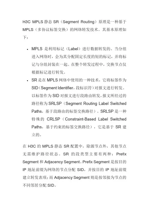
H3C MPLS静态SR(Segment Routing)原理是一种基于MPLS(多协议标签交换)的网络转发技术。
其基本原理如下:
•MPLS是利用标记(Label)进行数据转发的。
当分组进入网络时,会为其分配固定长度的短的标记,并将标记与分组封装在一起。
在整个转发过程中,交换节点仅根据标记进行转发。
•SR是在MPLS网络中使用的一种技术,它将标签作为SID(Segment Identifier,段标识符)对报文进行转发。
以标签作为SID对报文进行段路由转发,报文所经过的路径称为SRLSP(Segment Routing Label Switched Paths,基于段路由的标签交换路径)。
SRLSP是一种特殊的CRLSP(Constraint-Based Label Switched Paths,基于约束的标签交换路径),它是基于SR建立的。
在H3C的MPLS静态SR配置中,除源节点外,其他节点无需维护路径状态。
SR的段类型主要有两种:Prefix Segment和Adjacency Segment。
Prefix Segment是按目的IP地址前缀为网络的节点分配SID,并按目的IP地址前缀建立转发表项;而Adjacency Segment则是按邻接为节点的不同邻居分配SID。
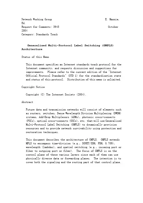
Network Working Group E. Mannie, Ed.Request for Comments: 3945 October 2004Category: Standards TrackGeneralized Multi-Protocol Label Switching (GMPLS) ArchitectureStatus of this MemoThis document specifies an Internet standards track protocol for the Internet community, and requests discussion and suggestions forimprovements. Please refer to the current edition of the "Internet Official Protocol Standards" (STD 1) for the standardization state and status of this protocol. Distribution of this memo is unlimited.Copyright NoticeCopyright (C) The Internet Society (2004).AbstractFuture data and transmission networks will consist of elements such as routers, switches, Dense Wavelength Division Multiplexing (DWDM) systems, Add-Drop Multiplexors (ADMs), photonic cross-connects(PXCs), optical cross-connects (OXCs), etc. that will use Generalized Multi-Protocol Label Switching (GMPLS) to dynamically provisionresources and to provide network survivability using protection and restoration techniques.This document describes the architecture of GMPLS. GMPLS extends MPLS to encompass time-division (e.g., SONET/SDH, PDH, G.709),wavelength (lambdas), and spatial switching (e.g., incoming port or fiber to outgoing port or fiber). The focus of GMPLS is on thecontrol plane of these various layers since each of them can use physically diverse data or forwarding planes. The intention is to cover both the signaling and the routing part of that control plane.Mannie Standards Track [Page 1]RFC 3945 GMPLS Architecture October 2004Table of Contents1. Introduction. . . . . . . . . . . . . . . . . . . . . . . . . 41.1. Acronyms & Abbreviations. . . . . . . . . . . . . . . . 4 1.2. Multiple Types of Switching and Forwarding Hierarchies. 51.3. Extension of the MPLS Control Plane . . . . . . . . . . 71.4. GMPLS Key Extensions to MPLS-TE . . . . . . . . . . . . 102. Routing and Addressing Model. . . . . . . . . . . . . . . . . 112.1. Addressing of PSC and non-PSC layers. . . . . . . . . . 132.2. GMPLS Scalability Enhancements. . . . . . . . . . . . . 132.3. TE Extensions to IP Routing Protocols . . . . . . . . . 143. Unnumbered Links. . . . . . . . . . . . . . . . . . . . . . . 153.1. Unnumbered Forwarding Adjacencies . . . . . . . . . . . 164. Link Bundling . . . . . . . . . . . . . . . . . . . . . . . . 164.1. Restrictions on Bundling. . . . . . . . . . . . . . . . 174.2. Routing Considerations for Bundling . . . . . . . . . . 174.3. Signaling Considerations. . . . . . . . . . . . . . . . 184.3.1. Mechanism 1: Implicit Indication. . . . . . . . 18 4.3.2. Mechanism 2: Explicit Indication by NumberedInterface ID. . . . . . . . . . . . . . . . . . 19 4.3.3. Mechanism 3: Explicit Indication by Unnumbered Interface ID. . . . . . . . . . . . . . . . . . 194.4. Unnumbered Bundled Link . . . . . . . . . . . . . . . . 194.5. Forming Bundled Links . . . . . . . . . . . . . . . . . 205. Relationship with the UNI . . . . . . . . . . . . . . . . . . 205.1. Relationship with the OIF UNI . . . . . . . . . . . . . 215.2. Reachability across the UNI . . . . . . . . . . . . . . 216. Link Management . . . . . . . . . . . . . . . . . . . . . . . 226.1. Control Channel and Control Channel Management. . . . . 236.2. Link Property Correlation . . . . . . . . . . . . . . . 246.3. Link Connectivity Verification. . . . . . . . . . . . . 246.4. Fault Management. . . . . . . . . . . . . . . . . . . . 256.5. LMP for DWDM Optical Line Systems (OLSs). . . . . . . . 267. Generalized Signaling . . . . . . . . . . . . . . . . . . . . 277.1. Overview: How to Request an LSP . . . . . . . . . . . . 297.2. Generalized Label Request . . . . . . . . . . . . . . . 307.3. SONET/SDH Traffic Parameters. . . . . . . . . . . . . . 317.4. G.709 Traffic Parameters. . . . . . . . . . . . . . . . 327.5. Bandwidth Encoding. . . . . . . . . . . . . . . . . . . 337.6. Generalized Label . . . . . . . . . . . . . . . . . . . 347.7. Waveband Switching. . . . . . . . . . . . . . . . . . . 347.8. Label Suggestion by the Upstream. . . . . . . . . . . . 357.9. Label Restriction by the Upstream . . . . . . . . . . . 357.10. Bi-directional LSP. . . . . . . . . . . . . . . . . . . 367.11. Bi-directional LSP Contention Resolution. . . . . . . . 377.12. Rapid Notification of Failure . . . . . . . . . . . . . 377.13. Link Protection . . . . . . . . . . . . . . . . . . . . 387.14. Explicit Routing and Explicit Label Control . . . . . . 39Mannie Standards Track [Page 2]RFC 3945 GMPLS Architecture October 20047.15. Route Recording . . . . . . . . . . . . . . . . . . . . 407.16. LSP Modification and LSP Re-routing . . . . . . . . . . 407.17. LSP Administrative Status Handling. . . . . . . . . . . 417.18. Control Channel Separation. . . . . . . . . . . . . . . 428. Forwarding Adjacencies (FA) . . . . . . . . . . . . . . . . . 438.1. Routing and Forwarding Adjacencies. . . . . . . . . . . 438.2. Signaling Aspects . . . . . . . . . . . . . . . . . . . 448.3. Cascading of Forwarding Adjacencies . . . . . . . . . . 449. Routing and Signaling Adjacencies . . . . . . . . . . . . . . 4510. Control Plane Fault Handling. . . . . . . . . . . . . . . . . 4611. LSP Protection and Restoration. . . . . . . . . . . . . . . . 4711.1. Protection Escalation across Domains and Layers . . . . 4811.2. Mapping of Services to P&R Resources. . . . . . . . . . 4911.3. Classification of P&R Mechanism Characteristics . . . . 4911.4. Different Stages in P&R . . . . . . . . . . . . . . . . 5011.5. Recovery Strategies . . . . . . . . . . . . . . . . . . 5011.6. Recovery mechanisms: Protection schemes . . . . . . . . 5111.7. Recovery mechanisms: Restoration schemes. . . . . . . . 5211.8. Schema Selection Criteria . . . . . . . . . . . . . . . 5312. Network Management. . . . . . . . . . . . . . . . . . . . . . 5412.1. Network Management Systems (NMS). . . . . . . . . . . . 5512.2. Management Information Base (MIB) . . . . . . . . . . . 5512.3. Tools . . . . . . . . . . . . . . . . . . . . . . . . . 5612.4. Fault Correlation Between Multiple Layers . . . . . . . 5613. Security Considerations . . . . . . . . . . . . . . . . . . . 5714. Acknowledgements. . . . . . . . . . . . . . . . . . . . . . . 5815. References. . . . . . . . . . . . . . . . . . . . . . . . . . 5815.1. Normative References. . . . . . . . . . . . . . . . . . 5815.2. Informative References. . . . . . . . . . . . . . . . . 5916. Contributors. . . . . . . . . . . . . . . . . . . . . . . . . 6317. Author's Address. . . . . . . . . . . . . . . . . . . . . . . 68 Full Copyright Statement. . . . . . . . . . . . . . . . . . . 69Mannie Standards Track [Page 3]RFC 3945 GMPLS Architecture October 20041. IntroductionThe architecture described in this document covers the main building blocks needed to build a consistent control plane for multipleswitching layers. It does not restrict the way that these layers work together. Different models can be applied, e.g., overlay,augmented or integrated. Moreover, each pair of contiguous layers may collaborate in different ways, resulting in a number of possible combinations, at the discretion of manufacturers and operators.This architecture clearly separates the control plane and theforwarding plane. In addition, it also clearly separates the control plane in two parts, the signaling plane containing the signaling protocols and the routing plane containing the routing protocols.This document is a generalization of the Multi-Protocol LabelSwitching (MPLS) architecture [RFC3031], and in some cases may differ slightly from that architecture since non packet-based forwarding planes are now considered. It is not the intention of this document to describe concepts already described in the current MPLSarchitecture. The goal is to describe specific concepts ofGeneralized MPLS (GMPLS).However, some of the concepts explained hereafter are not part of the current MPLS architecture and are applicable to both MPLS and GMPLS (i.e., link bundling, unnumbered links, and LSP hierarchy). Since these concepts were introduced together with GMPLS and since they are of paramount importance for an operational GMPLS network, they will be discussed here.The organization of the remainder of this document is as follows. We begin with an introduction of GMPLS. We then present the specific GMPLS building blocks and explain how they can be combined together to build an operational GMPLS network. Specific details of theseparate building blocks can be found in the corresponding documents.1.1. Acronyms & AbbreviationsAS Autonomous SystemBGP Border Gateway ProtocolCR-LDP Constraint-based Routing LDPCSPF Constraint-based Shortest Path FirstDWDM Dense Wavelength Division MultiplexingFA Forwarding AdjacencyGMPLS Generalized Multi-Protocol Label SwitchingIGP Interior Gateway ProtocolLDP Label Distribution ProtocolLMP Link Management ProtocolMannie Standards Track [Page 4]RFC 3945 GMPLS Architecture October 2004LSA Link State AdvertisementLSR Label Switching RouterLSP Label Switched PathMIB Management Information BaseMPLS Multi-Protocol Label SwitchingNMS Network Management SystemOXC Optical Cross-ConnectPXC Photonic Cross-ConnectRSVP ReSource reserVation ProtocolSDH Synchronous Digital HierarchySONET Synchronous Optical NetworksSTM(-N) Synchronous Transport Module (-N)STS(-N) Synchronous Transport Signal-Level N (SONET)TDM Time Division MultiplexingTE Traffic Engineering1.2. Multiple Types of Switching and Forwarding HierarchiesGeneralized MPLS (GMPLS) differs from traditional MPLS in that it supports multiple types of switching, i.e., the addition of support for TDM, lambda, and fiber (port) switching. The support for the additional types of switching has driven GMPLS to extend certain base functions of traditional MPLS and, in some cases, to addfunctionality. These changes and additions impact basic LSPproperties: how labels are requested and communicated, theunidirectional nature of LSPs, how errors are propagated, andinformation provided for synchronizing the ingress and egress LSRs. The MPLS architecture [RFC3031] was defined to support the forwardingof data based on a label. In this architecture, Label Switching Routers (LSRs) were assumed to have a forwarding plane that iscapable of (a) recognizing either packet or cell boundaries, and (b) being able to process either packet headers (for LSRs capable of recognizing packet boundaries) or cell headers (for LSRs capable of recognizing cell boundaries).The original MPLS architecture is here being extended to include LSRs whose forwarding plane recognizes neither packet, nor cellboundaries, and therefore, cannot forward data based on theinformation carried in either packet or cell headers. Specifically, such LSRs include devices where the switching decision is based on time slots, wavelengths, or physical ports. So, the new set of LSRs, or more precisely interfaces on these LSRs, can be subdivided into the following classes:Mannie Standards Track [Page 5]RFC 3945 GMPLS Architecture October 20041. Packet Switch Capable (PSC) interfaces:Interfaces that recognize packet boundaries and can forward data based on the content of the packet header. Examples includeinterfaces on routers that forward data based on the content of the IP header and interfaces on routers that switch data based on the content of the MPLS "shim" header.2. Layer-2 Switch Capable (L2SC) interfaces:Interfaces that recognize frame/cell boundaries and can switch data based on the content of the frame/cell header. Examples include interfaces on Ethernet bridges that switch data based on the content of the MAC header and interfaces on ATM-LSRs that forward data based on the ATM VPI/VCI.3. Time-Division Multiplex Capable (TDM) interfaces:Interfaces that switch data based on the data's time slot in a repeating cycle. An example of such an interface is that of a SONET/SDH Cross-Connect (XC), Terminal Multiplexer (TM), or Add- Drop Multiplexer (ADM). Other examples include interfacesproviding G.709 TDM capabilities (the "digital wrapper") and PDH interfaces.4. Lambda Switch Capable (LSC) interfaces:Interfaces that switch data based on the wavelength on which the data is received. An example of such an interface is that of a Photonic Cross-Connect (PXC) or Optical Cross-Connect (OXC) that can operate at the level of an individual wavelength. Additional examples include PXC interfaces that can operate at the level of agroup of wavelengths, i.e., a waveband and G.709 interfacesproviding optical capabilities.5. Fiber-Switch Capable (FSC) interfaces:Interfaces that switch data based on a position of the data in the (real world) physical spaces. An example of such an interface is that of a PXC or OXC that can operate at the level of a single or multiple fibers.A circuit can be established only between, or through, interfaces of the same type. Depending on the particular technology being used for each interface, different circuit names can be used, e.g., SDHcircuit, optical trail, light-path, etc. In the context of GMPLS, all these circuits are referenced by a common name: Label Switched Path (LSP).Mannie Standards Track [Page 6]RFC 3945 GMPLS Architecture October 2004The concept of nested LSP (LSP within LSP), already available in the traditional MPLS, facilitates building a forwarding hierarchy, i.e., a hierarchy of LSPs. This hierarchy of LSPs can occur on the same interface, or between different interfaces.For example, a hierarchy can be built if an interface is capable of multiplexing several LSPs from the same technology (layer), e.g., a lower order SONET/SDH LSP (e.g., VT2/VC-12) nested in a higher order SONET/SDH LSP (e.g., STS-3c/VC-4). Several levels of signal (LSP) nesting are defined in the SONET/SDH multiplexing hierarchy.The nesting can also occur between interface types. At the top of the hierarchy are FSC interfaces, followed by LSC interfaces,followed by TDM interfaces, followed by L2SC, and followed by PSC interfaces. This way, an LSP that starts and ends on a PSC interface can be nested (together with other LSPs) into an LSP that starts and ends on a L2SC interface. This LSP, in turn, can be nested (together with other LSPs) into an LSP that starts and ends on a TDM interface. In turn, this LSP can be nested (together with other LSPs) into an LSP that starts and ends on a LSC interface, which in turn can be nested (together with other LSPs) into an LSP that starts and ends on a FSC interface.1.3. Extension of the MPLS Control PlaneThe establishment of LSPs that span only Packet Switch Capable (PSC) or Layer-2 Switch Capable (L2SC) interfaces is defined for theoriginal MPLS and/or MPLS-TE control planes. GMPLS extends these control planes to support each of the five classes of interfaces (i.e., layers) defined in the previous section.Note that the GMPLS control plane supports an overlay model, anaugmented model, and a peer (integrated) model. In the near term, GMPLS appears to be very suitable for controlling each layerindependently. This elegant approach will facilitate the future deployment of other models.The GMPLS control plane is made of several building blocks asdescribed in more details in the following sections. These building blocks are based on well-known signaling and routing protocols that have been extended and/or modified to support GMPLS. They use IPv4 and/or IPv6 addresses. Only one new specialized protocol is required to support the operations of GMPLS, a signaling protocol for link management [LMP].GMPLS is indeed based on the Traffic Engineering (TE) extensions to MPLS, a.k.a. MPLS-TE [RFC2702]. This, because most of thetechnologies that can be used below the PSC level requires someMannie Standards Track [Page 7]RFC 3945 GMPLS Architecture October 2004traffic engineering. The placement of LSPs at these levels needs in general to consider several constraints (such as framing, bandwidth, protection capability, etc) and to bypass the legacy Shortest-Path First (SPF) algorithm. Note, however, that this is not mandatory and that in some cases SPF routing can be applied.In order to facilitate constrained-based SPF routing of LSPs, nodes that perform LSP establishment need more information about the links in the network than standard intra-domain routing protocols provide. These TE attributes are distributed using the transport mechanisms already available in IGPs (e.g., flooding) and taken intoconsideration by the LSP routing algorithm. Optimization of the LSP routes may also require some external simulations using heuristics that serve as input for the actual path calculation and LSPestablishment process.By definition, a TE link is a representation in the IS-IS/OSPF Link State advertisements and in the link state database of certainphysical resources, and their properties, between two GMPLS nodes. TE Links are used by the GMPLS control plane (routing and signaling) for establishing LSPs.Extensions to traditional routing protocols and algorithms are needed to uniformly encode and carry TE link information, and explicitroutes (e.g., source routes) are required in the signaling. Inaddition, the signaling must now be capable of transporting therequired circuit (LSP) parameters such as the bandwidth, the type of signal, the desired protection and/or restoration, the position in a particular multiplex, etc. Most of these extensions have already been defined for PSC and L2SC traffic engineering with MPLS. GMPLSprimarily defines additional extensions for TDM, LSC, and FSC traffic engineering. A very few elements are technology specific.Thus, GMPLS extends the two signaling protocols defined for MPLS-TE signaling, i.e., RSVP-TE [RFC3209] and CR-LDP [RFC3212]. However, GMPLS does not specify which one of these two signaling protocols must be used. It is the role of manufacturers and operators toevaluate the two possible solutions for their own interest.Since GMPLS signaling is based on RSVP-TE and CR-LDP, it mandates a downstream-on-demand label allocation and distribution, with ingress initiated ordered control. Liberal label retention is normally used, but conservative label retention mode could also be used.Mannie Standards Track [Page 8]RFC 3945 GMPLS Architecture October 2004Furthermore, there is no restriction on the label allocationstrategy, it can be request/signaling driven (obvious for circuit switching technologies), traffic/data driven, or even topologydriven. There is also no restriction on the route selection;explicit routing is normally used (strict or loose) but hop-by-hop routing could be used as well.GMPLS also extends two traditional intra-domain link-state routing protocols already extended for TE purposes, i.e., OSPF-TE [OSPF-TE] and IS-IS-TE [ISIS-TE]. However, if explicit (source) routing is used, the routing algorithms used by these protocols no longer need to be standardized. Extensions for inter-domain routing (e.g., BGP) are for further study.The use of technologies like DWDM (Dense Wavelength DivisionMultiplexing) implies that we can now have a very large number ofparallel links between two directly adjacent nodes (hundreds ofwavelengths, or even thousands of wavelengths if multiple fibers are used). Such a large number of links was not originally considered for an IP or MPLS control plane, although it could be done. Some slight adaptations of that control plane are thus required if we want to better reuse it in the GMPLS context.For instance, the traditional IP routing model assumes theestablishment of a routing adjacency over each link connecting two adjacent nodes. Having such a large number of adjacencies does not scale well. Each node needs to maintain each of its adjacencies one by one, and link state routing information must be flooded throughout the network.To solve this issue the concept of link bundling was introduced. Moreover, the manual configuration and control of these links, even if they are unnumbered, becomes impractical. The Link Management Protocol (LMP) was specified to solve these issues.LMP runs between data plane adjacent nodes and is used to manage TE links. Specifically, LMP provides mechanisms to maintain control channel connectivity (IP Control Channel Maintenance), verify the physical connectivity of the data-bearing links (Link Verification), correlate the link property information (Link Property Correlation), and manage link failures (Fault Localization and Fault Notification).A unique feature of LMP is that it is able to localize faults in both opaque and transparent networks (i.e., independent of the encoding scheme and bit rate used for the data).LMP is defined in the context of GMPLS, but is specifiedindependently of the GMPLS signaling specification since it is a local protocol running between data-plane adjacent nodes.Mannie Standards Track [Page 9]RFC 3945 GMPLS Architecture October 2004Consequently, LMP can be used in other contexts with non-GMPLSsignaling protocols.MPLS signaling and routing protocols require at least one bi-directional control channel to communicate even if two adjacent nodes are connected by unidirectional links. Several control channels can be used. LMP can be used to establish, maintain and manage these control channels.GMPLS does not specify how these control channels must beimplemented, but GMPLS requires IP to transport the signaling and routing protocols over them. Control channels can be either in-band or out-of-band, and several solutions can be used to carry IP. Note also that one type of LMP message (the Test message) is used in-band in the data plane and may not be transported over IP, but this is a particular case, needed to verify connectivity in the data plane.1.4. GMPLS Key Extensions to MPLS-TESome key extensions brought by GMPLS to MPLS-TE are highlighted in the following. Some of them are key advantages of GMPLS to control TDM, LSC and FSC layers.- In MPLS-TE, links traversed by an LSP can include an intermix of links with heterogeneous label encoding (e.g., links betweenrouters, links between routers and ATM-LSRs, and links between ATM-LSRs. GMPLS extends this by including links where the label is encoded as a time slot, or a wavelength, or a position in the (real world) physical space.- In MPLS-TE, an LSP that carries IP has to start and end on arouter. GMPLS extends this by requiring an LSP to start and end on similar type of interfaces.- The type of a payload that can be carried in GMPLS by an LSP is extended to allow such payloads as SONET/SDH, G.709, 1Gb or 10Gb Ethernet, etc.- The use of Forwarding Adjacencies (FA) provides a mechanism that can improve bandwidth utilization, when bandwidth allocation can be performed only in discrete units. It offers also a mechanism to aggregate forwarding state, thus allowing the number ofrequired labels to be reduced.Mannie Standards Track [Page 10]RFC 3945 GMPLS Architecture October 2004- GMPLS allows suggesting a label by an upstream node to reduce the setup latency. This suggestion may be overridden by a downstream node but in some cases, at the cost of higher LSP setup time.- GMPLS extends on the notion of restricting the range of labels that may be selected by a downstream node. In GMPLS, an upstream node may restrict the labels for an LSP along either a single hop or the entire LSP path. This feature is useful in photonicnetworks where wavelength conversion may not be available.- While traditional TE-based (and even LDP-based) LSPs areunidirectional, GMPLS supports the establishment of bi-directional LSPs.- GMPLS supports the termination of an LSP on a specific egress port, i.e., the port selection at the destination side.- GMPLS with RSVP-TE supports an RSVP specific mechanism for rapid failure notification.Note also some other key differences between MPLS-TE and GMPLS:- For TDM, LSC and FSC interfaces, bandwidth allocation for an LSP can be performed only in discrete units.- It is expected to have (much) fewer labels on TDM, LSC or FSC links than on PSC or L2SC links, because the former are physical labels instead of logical labels.2. Routing and Addressing ModelGMPLS is based on the IP routing and addressing models. This assumesthat IPv4 and/or IPv6 addresses are used to identify interfaces but also that traditional (distributed) IP routing protocols are reused. Indeed, the discovery of the topology and the resource state of all links in a routing domain is achieved via these routing protocols.Since control and data planes are de-coupled in GMPLS, control-plane neighbors (i.e., IGP-learnt neighbors) may not be data-planeneighbors. Hence, mechanisms like LMP are needed to associate TE links with neighboring nodes.IP addresses are not used only to identify interfaces of IP hosts and routers, but more generally to identify any PSC and non-PSCinterfaces. Similarly, IP routing protocols are used to find routes for IP datagrams with a SPF algorithm; they are also used to find routes for non-PSC circuits by using a CSPF algorithm.Mannie Standards Track [Page 11]RFC 3945 GMPLS Architecture October 2004However, some additional mechanisms are needed to increase thescalability of these models and to deal with specific trafficengineering requirements of non-PSC layers. These mechanisms will be introduced in the following.Re-using existing IP routing protocols allows for non-PSC layers taking advantage of all the valuable developments that took place since years for IP routing, in particular, in the context of intra- domain routing (link-state routing) and inter-domain routing (policy routing).In an overlay model, each particular non-PSC layer can be seen as a set of Autonomous Systems (ASs) interconnected in an arbitrary way. Similarly to the traditional IP routing, each AS is managed by a single administrative authority. For instance, an AS can be anSONET/SDH network operated by a given carrier. The set ofinterconnected ASs can be viewed as SONET/SDH internetworks.Exchange of routing information between ASs can be done via aninter-domain routing protocol like BGP-4. There is obviously a huge value of re-using well-known policy routing facilities provided by BGP in a non-PSC context. Extensions for BGP traffic engineering (BGP-TE) in the context of non-PSC layers are left for further study.Each AS can be sub-divided in different routing domains, and each can run a different intra-domain routing protocol. In turn, eachrouting-domain can be divided in areas.A routing domain is made of GMPLS enabled nodes (i.e., a network device including a GMPLS entity). These nodes can be either edge nodes (i.e., hosts, ingress LSRs or egress LSRs), or internal LSRs. An example of non-PSC host is an SONET/SDH Terminal Multiplexer (TM). Another example is an SONET/SDH interface card within an IP router or ATM switch.Note that traffic engineering in the intra-domain requires the use of link-state routing protocols like OSPF or IS-IS.GMPLS defines extensions to these protocols. These extensions are needed to disseminate specific TDM, LSC and FSC static and dynamic characteristics related to nodes and links. The current focus is onMannie Standards Track [Page 12]RFC 3945 GMPLS Architecture October 2004intra-area traffic engineering. However, inter-area trafficengineering is also under investigation.2.1. Addressing of PSC and non-PSC Layers。

VPN的典型隧道协议隧道技术是一种通过使用互联网络的基础设施在网络之间传递数据的方式。
使用隧道传递的数据(或负载)可以是不同协议的数据桢(此字不正确)或包。
隧道协议将这些其它协议的数据桢或包重新封装在新的包头中发送。
新的包头提供了路由信息,从而使封装的负载数据能够通过互联网络传递.被封装的数据包在隧道的两个端点之间通过公共互联网络进行路由.被封装的数据包在公共互联网络上传递时所经过的逻辑路径称为隧道。
一旦到达网络终点,数据将被解包并转发到最终目的地。
注意隧道技术是指包括数据封装,传输和解包在内的全过程。
1、点对点隧道协议(PPTP)点对点隧道协议(PPTP,Point-to-point Tunneling Protocol)是一种用于让远程用户拨号连接到本地ISP,通过因特网安全远程访问公司网络资源的新型技术.PPTP对PPP协议本身并没有做任何修改,只是使用PPP拨号连接,然后获取这些PPP包,并把它们封装进GRE头中。
PPTP使用PPP协议的PAP或CHAP(MS-CHAP)进行认证,另外也支持Microsoft公司的点到点加密技术(MPPE)。
PPTP支持的是一种客户-LAN型隧道的VPN实现。
传统网络接入服务器(NAS)执行以下功能:它是PSTN或ISDN的本地接口,控制着外部的MODEM或终端适配器:它是PPP链路控制协议会话的逻辑终点;它是PPP认证协议的执行者;它为PPP多链路由协议进行信道汇聚管理;它是各种PPP网络控制协议的逻辑终点。
PPTP协议将上述功能分解成由两部分即PAC(PPTP接入集中器)和PNS(PPTP 网络服务器)来分别执行。
这样一来,拨号PPP链路的终点就延伸至PNS。
PPTP协议正是利用了“NAS功能的分解”这样的机制支持在因特网上的VPN实现。
ISP的NAS将执行PPTP协议中指定的PAC的功能。
而企业VPN中心服务器将执行PNS的功能,通过PPTP,远程拥护首先拨号到本地ISP的NAS,访问企业的网络和应用,而不再需要直接拨号至企业的网络,这样,由GRE将PPP报文封装成IP报文就可以在PAC-PNS 之间经由因特网传递,即在PAC和PNS之间为用户的PPP会话建立一条PPTP隧道。
交换机术语1、5-4-3规则:在连接过程中最多可以使用四个中继器连接最多五个以太网段3 表示高密度以太网网段的最大数量。
2、BRI:基本速率接口。
ISDN接口由用于话音、视频和数据屯路交换通信的两个B信道和一个D信道组成。
3、COS名:是一种支持时间敏感型应用的技术指标,它通过优先权数据队列机制,保证重要数据(如时间敏感型数据、实时数据)比次要数据获得更高的传输优先权。
是目前新型高档交换机的一项技术指标。
4、MPLS:MPLS(MultiProtocol Label Switching,多协议标记交换)是IETF制定的第三层交换规范。
MPLS类似Cisco的标记交换,也使用包含转发信息的标记,标记被位于网络边缘的路由器(称为标记边缘路由器,LER)附加到IP信息包。
位于网络核心的路由器(称为标记交换路由器,LSR)查验标记,其查验速度比查找路由选择表中的目的地址快。
如果在Internet上充分采用MPLS,MPLS有望提供充分支持实时音视频所需的服务质量(QoS)和保证带宽的服务级协议。
5、NAT:网络地址变换。
减少对全球唯一的IP地址需求的机制。
NAT允许一个组织使用非全球唯一的地址连入Internet,但这要通过变换将这些地址变换到全球的可供路由的地址空间。
也称作网络地址翻译器。
6、PBX:专用小交换机。
它位于用户住地的数字或模拟电话交换机,用来连接专用电话网和公共电话网。
7、SNMP:(简单网络管理协议),TCP/IP协议组中的一个协议,用于TCP/IP网络的管理,采用代理和工作站的管理方式。
8、VLAN:用户依靠自己的逻辑设定将局域网划分成的多个虚拟网段,各虚拟网段间不能自由通讯(可通过路由器的路由来实现数据交流),这样做的好处是提高虚网内数据传递的效率,并隔离广播,提高安全性。
9、W AN:广域网。
指的是能在很宽的地理区域内为用户服务的数据通信网络,此网络通常便用由公共设备商提供的传输设备。
第1章交换概论1.2 通信网中用户线上传输的是什么信号?中继(E1)线上是什么信号?数据传输速率?答:模拟信号。
数字信号。
2.048Mbps.1.3 说明目前常用的交换方式有哪几种?各有什么特点及应用场合?答:电路交换,多速率电路交换.快速电路交换,分组交换, 帧交换, 帧中继、ATM交换, IP交换, 多协议标记交换(MPLS), 光交换, 软交换.。
电路交换:①信息传送的最小单位是时隙②同步时分复用(固定分配带宽) ③面向物理连接的工作方式④信息具有透明性⑤信息传送无差错控制⑥基于呼叫损失制的流量控制多速率电路交换:本质上还是电路交换,具有电路交换的主要特点。
不同的是:电路交换方式只提供64kbps的单一速率,多速率电路交换方式可以为用户提供多种速率。
即多速率电路交换,有一个固定的基本信道速率,如64kbps、2Mbps等,几个这样的基本信道捆绑起来构成一个速率更高的信道,实现多速率交换。
这个更高的速率一定是基本信道速率的整数倍。
窄带综合业务数字网(N-ISDN)中,可视电话业务采用的就是多速率电路交换方式。
快速电路交换:动态分配带宽和网络资源,用户不传输数据时,不建立传输通道和物理连接,当有信息传送时才快速建立通道。
适应突发业务。
分组交换:1.报文交换的特征是交换机要对用户的信息进行存储和处理,即信息是不透明传输。
数据通信——非话业务。
2分组交换:①信息传送的最小单位是分组。
②面向逻辑连接和无连接两种工作方式③统计时分复用(按需分配带宽) 基本原理是把时间划分为不等长的时间片,长短不同的时间片就是传送不同长度分组所需要的时间,每路通信按需分配时间片,当通信需要传送的分组多时,所占用时间片的个数就多,反之,所占用时间片的个数就少,不传输信息时不分配带宽。
由此可见,统计时分复用是按需分配带宽(动态分配带宽)的。
④标志化信道:在统计时分复用中,靠分组头中的标志来区分不同的通信分组。
具有相同标志的分组属于同一个通信,也就构成了一个子信道,识别这个子信道的标志也叫做信道标志,该子信道被称为标志化信道。