毕业论文外文翻译-冲压模具技术
- 格式:doc
- 大小:67.00 KB
- 文档页数:16

冲压工艺与外文翻译文档1. The mold designing and manufacturingThe mold is the manufacturing industry important craft foundation, in our country, the mold manufacture belongs to the special purpose equipment manufacturing industry. China although very already starts to make the mold and the use mold, but long-term has not formed the industry. Straight stabs 0 centuries 80's later periods, the Chinese mold industry only then drives into the development speedway. Recent years, not only the state-owned mold enterprise had the very big development, the three investments enterprise, the villages and towns (individual) the mold enterprise's development also rapid quietly.Although the Chinese mold industrial development rapid, but compares with the demand, obviously falls short of demand, its main gap concentrates precisely to, large-scale, is complex, the long life mold domain. As a result of in aspect and so on mold precision, life, manufacture cycle and productivity, China and the international average horizontal and the developed country still had a bigger disparity, therefore, needed massively to import the mold every year .The Chinese mold industry must continue to sharpen the productivity, from now on will have emphatically to the profession internal structure adjustment and the state-of-art enhancement. The structure adjustment aspect, mainly is the enterprise structure to the specialized adjustment, the product structure to center the upscale mold development, to the import and export structure improvement, center the upscale automobile cover mold forming analysis and the structure improvement, the multi-purpose compound mold and the compound processing and the laser technology in the mold design manufacture application, the high-speed cutting, the super finishing and polished the technology, the information direction develops . The recent years, the mold profession structure adjustment and the organizational reform step enlarges, mainly displayed in, large-scale, precise, was complex, the long life, center the upscale mold and the mold standard letter development speed is higher than the common mold product; The plastic mold and the compression casting mold proportion increases; Specialized mold factory quantity and its productivity increase; “The three investments" and the private enterprise developsrapidly; The joint stock system transformation step speedsup and so on. Distributes from the area looked, take Zhejiang Delta and Yangtze River delta as central southeast coastal area development quickly to mid-west area, south development quickly to north. At present develops quickest, the mold produces the most centralized province is Guangdong and Zhejiang, places such as Jiangsu, Shanghai, Anhui and Shandong also has a bigger development in recent years.2. Mold Present Status of TechnologyTechni cal level of China’s mold industry currently uneven, with wide disparities generally speaking, with the developed industrial countries, Hong Kong and Taiwan advanced level, there is a large gap.The use of CAD / CAM / CAE / CAPP and other technical design and manufacture molds, either wide application, or technical level, there is a big gap between both. In the application of CAD technology design molds, only about 10% of the mold used in the design of CAD, aside from drawing board still has a long way to go; in the application of CAE design and analysis of mold calculation, it was just started, most of the game is still in trial stages and animation; in the application of CAM technology manufacturing molds, first, the lack of advanced manufacturingequipment, and second, the existing process equipment (including the last 10 years the introduction of advanced equipment) or computer standard (IBM PC and compatibles, HP workstations, etc.) different, or because of differences in bytes, processing speed differences, differences in resistance to electromagnetic interference, networking is low, only about 5% of the mold manufacturing equipment of recent work in this task; in the application process planning CAPP technology, basically a blank state, based on the need for a lot of standardization work; in the mold common technology, such as mold rapid prototyping technology, polishing, electroforming technologies, surface treatment technology aspects of CAD / CAM technology in China has just started. Computer-aided technology, software development, is still at low level, the accumulation of knowledge and experience required. Most of our mold factory, mold processing equipment shop old, long in the length of civilian service, accuracy, low efficiency, still use theordinary forging, turning, milling, planning, drilling, grinding and processing equipment, mold, heat treatment is still in use salt bath, box-type furnace, operating with the experience of workers, poorly equipped, high energy consumption. Renewal ofequipment is slow, technological innovation; technological progress is not much intensity. Although in recent years introduced many advanced mold processing equipment, but are too scattered, or not complete, only about 25% utilization, equipment, some of the advanced functions are not given full play.3. Die trend(1) Mold software features integratedDie software features of integrated software modules required relatively complete, while the function module using the same data model, in order to achieve Syndicated news management and sharing of information to support the mold design, manufacture, assembly, inspection, testing and production management of the entire process to achieve optimal benefits. Series such as the UK Delcam's software will include a surface / solid geometric modeling, engineering drawing complex geometry, advanced rendering industrial design, plastic mold design expert system, complex physical CAM, artistic design and sculpture automatic programming system, reverse engineering and complex systems physical line measurement systems. A higher degree of integration of the software includes:Pro / __R, UG and CATIA, etc.. Shanghai Jiao tong University, China with finite element analysis of metal plastic forming systems and Die CAD / CAM systems; Beijing Bei hang Haier Software Ltd. CAXA Series software; Jilin Gold Grid Engineering Research Center of the stamping die mold CAD / CAE / CAM systems.(2) Mold design, analysis and manufacture of three-dimensionalTwo-dimensional mold of traditional structural design can no longer meet modern technical requirements of production and integration. Mold design, analysis, manufacturing three-dimensional technology, paperless software required to mold a new generation of three-dimensional, intuitive sense to design the mold, using three-dimensional digital model can be easily used in the product structure of CAE analysis, tooling manufacturability evaluation and CNC machining, forming processsimulation and information management and sharing. Such as Pro / E, UG and CATIA software such as with parametric, feature-based, all relevant characteristics, so that mold concurrent engineering possible. In addition, Cimarron company Mold expert, Delcam's Ps-mold and Hitachi Shipbuilding ofSpace-E/mold are professional injection mold 3D design software, interactive 3D cavity, core design, mold base design configuration and typical structure . Australian company Mold flow realistic three-dimensional flow simulation software MoldflowAdvisers been widely praised by users and applications. China Huazhong University of Science has developed similar software HSC3D4.5F and Zhengzhou University, Z-mold software. For manufacturing, knowledge-based intelligent software function is a measure of die important sign of advanced and practical one. Such as injection molding experts Cimarron’s software can automatically generate parting direction based parting line and parting surface, generate products corresponding to the core and cavity, implementation of all relevant parts mold, and for automatically generated BOM Form NC drilling process, and can intelligently process parameter setting, calibration and other processing results.(3) Mold software applications, networking trendWith the mold in the enterprise competition, cooperation, production and management, globalization, internationalization, and the rapid development of computer hardware and software technology, the Internet has made in the mold industry, virtualdesign, and agile manufacturing technology both necessary and possible.4. Heat Treatment of DieTraditional die and mould design, mainly by experience or semi―experience,is isolated from manufacturing process. Before the design is finalized,the scheme of die and mould is usually modified time and again,thus some disadvantages come into being, such as long development period, high cost and uncertain practical effect. Due to strong desires for precision, service life, development period and cost, modern die and mould should be designed and manufactured perfectly. Therefore more and more advanced technologies and innovations have been applied, for example, concurrentengineering, agile manufacturing virtual manufacturing, collaborative design, etc. Heat treatment of die and mould is as important as design, manufacture and assembly because it has a vital effect on manufacture,assembly and service life.Design and manufacture of die and mould have progressed rapidly,but heat treatment lagged seriously behind them.As die and mould industry develops,heat treatment must ensure die and mould there are good state of manufacture,assembly andwear―resistant properties by request. Impertinent heat treatment can influence die and mould manufacturing such as over―hard and―soft and assembly.Traditionally the heat treatment process was made out according to the methods and properties brought forward by designer.This could make the designers of die and mould and heat treatment diverge from each other,for the designers of die and mould could not fully realize heat treatment process and materials properties,and contrarily the designers rarely understood the service environment and designing thought. These divergences will impact the progress of die and mould to a great extent. Accordingly,if the process design of heat treatment is considered in the early designing stage,the aims of shortening development period,reducing cost and stabilizing quality will be achieved and the sublimation of development pattern from serial to concurrent will be realized.Concurrent engineering takes computer integration system as a carrier, at the very start subsequent each stage and factors have been considered such as manufacturing,heat treating,properties and so forth in order to avoid the error.The concurrent pattern has dismissed the defect of serial pattern, which bringabout a revolution against serial pattern.In the present work.the heat treatment was integrated into the concurrent circumstance of the die and mould development,and the systemic and profound research was performed.5. SummaryThe 21st century, in the new situation of economic globalization, with capital, technology and labor market re-integration of equipment manufacturing in China after joining the WTO will become the world's equipment manufacturing base. In the modern manufacturing industry, no matter which industry, engineering equipment, are increasingly used to provide the products from the mold industry. In order to meet the user's high-precision mold manufacturing, short delivery time, the urgent demand low-cost, mold industry is extensive application of modern advanced manufacturing technology to speed up the mold industry, technological progress, to meet the basic sectors of the mold process equipment urgent needs.。

Injection MoldingThe basic concept of injection molding revolves around the ability of a thermoplastic material to be softened by heat and to harden when cooled .In most operations ,granular material (the plastic resin) is fed into one end of the cylinder (usually through a feeding device known as a hopper ),heated, and softened(plasticized or plasticized),forced out the other end of the cylinder, while it is still in the form of a melt, through a nozzle into a relatively cool mold held closed under pressure.Here,the melt cools and hardens until fully set-up. The mold is then opened, the piece ejected, and the sequence repeated.Thus, the significant elements of an injection molding machine become: 1) the way in which the melt is plasticized (softened) and forced into the mold (called the injection unit);2) the system for opening the mold and closing it under pressure (called the clamping unit);3) the type of mold used;4) the machine controls.The part of an injection-molding machine, which converts a plastic material from a sold phase to homogeneous seni-liguid phase by raising its temperature .This unit maintains the material at a present temperature and force it through the injection unit nozzle into a mold .The plunger is a combination of the injection and plasticizing device in which a heating chamber is mounted between the plunger and mold. This chamber heats the plastic material by conduction .The plunger, on each stroke; pushes unbelted plastic material into the chamber, which in turn forces plastic melt at the front of the chamber out through the nozzleThe part of an injection molding machine in which the mold is mounted, and which provides the motion and force to open and close the mold and to hold the mold close with force during injection .This unit can also provide other features necessary for the effective functioning of the molding operation .Movingplate is the member of the clamping unit, which is moved toward a stationary member. the moving section of the mold is bolted to this moving plate .This member usually includes the ejector holes and mold mounting pattern of blot holes or “T” slots .Stationary plate is the fixed member of the clamping unit on which the stationary section of the mold is bolted .This member usually includes a mold-mounting pattern of boles or “T” slots. Tie rods are member of the clamping force actuating mechanism that serve as the tension member of the clamp when it is holding the mold closed. They also serve as a gutted member for the movable plate .Ejector is a provision in the clamping unit that actuates a mechanism within the mold to eject the molded part(s) from the mold .The ejection actuating force may be applied hydraulically or pneumatically by a cylinder(s) attached to the moving plate, or mechanically by the opening stroke of the moving plate.Methods of melting and injecting the plastic differ from one machine to another and are constantly being implored .conventional machines use a cylinder and piston to do both jobs .This method simplifies machine construction but makes control of injection temperatures and pressures an inherently difficult problem .Other machines use a plasticizing extruder to melt the plastic and piston to inject it while some hare been designed to use a screw for both jobs :Nowadays, sixty percent of the machines use a reciprocating screw,35% a plunger (concentrated in the smaller machine size),and 5%a screw pot.Many of the problems connected with in ejection molding arise because the densities of polymers change so markedly with temperature and pressure. thigh temperatures, the density of a polymer is considerably cower than at room temperature, provided the pressure is the same.Therefore,if molds were filled at atmospheric pressure, “shrinkage” would make the molding deviate form the shape of the mold.To compensate for this poor effect, molds are filled at high pressure. The pressure compresses the polymer and allows more materials to flow into the mold, shrinkage is reduced and better quality moldings are produced.Cludes a mold-mounting pattern of bolt holes or “T” slots. Tie rods are members of the clamping force actuating mechanism that serve as the tension members of clamp when it is holding the mold closed. Ejector is a provision in the calming unit that actuates a mechanism within the mold to eject the molded part(s) form the mold. The ejection actuating force may be applied hydraulically or pneumatically by a cylinder(s) attached to the moving plate, or mechanically by the opening stroke of the moving plate.The function of a mold is twofold: imparting the desired shape to the plasticized polymer and cooling the injection molded part. It is basically made up of two sets of components: the cavities and cores and the base in which the cavities and cores are mounted. The mold ,which contains one or more cavities, consists of two basic parts :(1) a stationary molds half one the side where the plastic is injected,(2)Moving half on the closing or ejector side of the machine. The separation between the two mold halves is called the parting line. In some cases the cavity is partly in the stationary and partly in the moving section. The size and weight of the molded parts limit the number of cavities in the mold and also determine the machinery capacity required. The mold components and their functions are as following:(1)Mold Base-Hold cavity (cavities) in fixed, correctposition relative to machine nozzle.(2)Guide Pins-Maintain Proper alignment of entry into moldinterior.(3)Spree Bushing (spree)-Provide means of entry into moldinterior.(4)Runners-Conroy molten plastic from spree to cavities.(5)Gates-Control flow into cavities.(6)Cavity (female) and Force (male)-Control the size,shape and surface of mold article.(7)Water Channels-Control the temperature of mold surfacesto chill plastic to rigid state.(8)Side (actuated by came, gears or hydrauliccylinders)-Form side holes, slots, undercuts and threaded sections.(9)Vent-Allow the escape of trapped air and gas.(10)Ejector Mechanism (pins, blades, stripper plate)-Ejectrigid molded article form cavity or force.(11)Ejector Return Pins-Return ejector pins to retractedposition as mold closes for next cycle.The distance between the outer cavities and the primary spree must not be so long that the molten plastic loses too much heat in the runner to fill the outer cavities properly. The cavities should be so arranged around the primary spree that each receives its full and equal share of the total pressure available, through its own runner system (or the so-called balanced runner system).The requires the shortest possible distance between cavities and primary sprue, equal runner and gate dimension, and uniform culling.注射成型注射成型的基本概念是使热塑性材料在受热时熔融,冷却时硬化,在大部分加工中,粒状材料(即塑料树脂)从料筒的一端(通常通过一个叫做“料斗”的进料装置)送进,受热并熔融(即塑化或增塑),然后当材料还是溶体时,通过一个喷嘴从料筒的另一端挤到一个相对较冷的压和封闭的模子里。

模具设计与制造专业外文翻译--冲压成形与板材冲压外文原文Characteristics and Sheet Metal Forming1.The article overviewStamping is a kind of plastic forming process in which a part is produced by means of the plastic forming the material under the action of a die. Stamping is usually carried out under cold state, so it is also called stamping. Heat stamping is used only when the blank thickness is greater than 8-100mm. The blank material for stamping is usually in the form of sheet or strip, and therefore it is also called sheet metal forming. Some non-metal sheets (such as plywood, mica sheet, asbestos, leather)can also be formed by stamping.Stamping is widely used in various fields of the metalworking industry, and it plays a crucial role in the industries for manufacturing automobiles, instruments, military parts and household electrical appliances, etc.The process, equipment and die are the three foundational problems that needed to be studied in stamping.The characteristics of the sheet metal forming are as follows:(1) High material utilization(2) Capacity to produce thin-walled parts of complex shape.(3) Good interchangeability between stamping parts due to precision in shape and dimension.(4) Parts with lightweight, high-strength and fine rigidity can be obtained. (5) High productivity, easy to operate and to realize mechanization and automatization.The manufacture of the stamping die is costly, and therefore it only fits to mass production. For the manufacture of products in small batch and rich variety, the simple stamping die and the new equipment such as a stamping machining center, are usually adopted to meet the market demands.The materials for sheet metal stamping include mild steel, copper, aluminum, magnesium alloy and high-plasticity alloy-steel, etc.Stamping equipment includes plate shear punching press. The former shears plate into strips with a definite width, which would be pressed later. The later can be used both in shearing and forming.2(Characteristics of stamping formingThere are various processes of stamping forming with different working patterns and names. But these processes are similar to each other in plastic deformation. There are following conspicuous characteristics in stamping:,1,(The force per unit area perpendicular to the blank surface isnot large but is enough to cause the material plastic deformation. It is much less than the inner stresses on the plate plane directions. In most cases stamping forming can be treated approximately as that of the plane stress state to simplify vastly the theoretical analysis and the calculation of the process parameters.,2,(Due to the small relative thickness, the anti-instability capability of the blank is weak under compressive stress. As a result, the stamping process is difficult to proceed successfully without using the anti-instability device (such as blank holder). Therefore the varieties of the stamping processes dominated by tensile stress are more than dominated by compressive stress.,3,(During stamping forming, the inner stress of the blank is equal to or sometimes less than the yield stress of the material. In this point, the stamping is different from the bulk forming. During stamping forming, the influence of the hydrostatic pressure of the stress statein the deformation zone to the forming limit and the deformation resistance is not so important as to the bulk forming. In some circumstances, such influence may be neglected. Even in the case when this influence should be considered, the treating method is also different from that of bulk forming. ,4,(In stamping forming, the restrain action of the die to the blank is not severs as in the case of the bulk forming (such as die forging). In bulk forming, the constraint forming is proceeded by the die with exactly the same shape of the part. Whereas in stamping, in most cases, the blank has a certain degree of freedom, only one surface of the blank contacts with the die. In some extra cases, such as the forming of the blank on the deforming zone contact with the die. The deformation in these regions are caused and controlled by the die applying an external force to its adjacent area. Due to the characteristics of stamping deformation and mechanicsmentioned above, the stamping technique is different form the bulk metal forming:,1,(The importance or the strength and rigidity of the die in stamping forming is less than that in bulk forming because the blank can be formed without applying large pressure per unit area on its surface. Instead, the techniques of the simple die and the pneumatic and hydraulic forming are developed.2,2,(Due to the plane stress or simple strain state in comparisonwith bulk forming, more research on deformation or force and power parameters has been done. Stamping forming can be performed by more reasonable scientific methods. Based on the real time measurement and analysis on the sheet metal properties and stamping parameters, by means of computer and some modern testing apparatus, research on the intellectualized control of stamping process is also inproceeding. ,3,(It is shown that there is a close relationship between stamping forming and raw material. The research on the properties of the stamping forming, that is, forming ability and shape stability, has become a key point in stamping technology development, but also enhances the manufacturing technique of iron and steel industry, and provides a reliable foundation for increasing sheet metal quality. 3(Categories of stamping formingMany deformation processes can be done by stamping, the basic processes of the stamping can be divided into two kinds: cutting and forming.Cutting is a shearing process that one part of the blank is cut from the other. It mainly includes blanking, punching, trimming, parting and shaving, where punching and blanking are the most widely used. Forming is a process that one part of the blank has some displacement from the other. It mainly includes deep drawing, bending, local forming, bulging, flanging, necking, sizing and spinning.In substance, stamping forming is such that the plastic deformation occurs in the deformation zone of the stamping blank caused by the external force. The stress state and deformation characteristic of the deformation zone are the basic factors to decide the properties of the stamping forming. Based on the stress state and deformation characteristics of the deformation zone, the forming methods can be divided into several categories with the same forming properties and be studied systematically. The deformation zone in almost all types of stamping forming is in the plane stress state. Usually there is no force or only small force applied on the blank surface. When is assumed that the stress perpendicular to the blank surface equals to zero, two principal stresses perpendicular to each other and act on the blank surface produce the plastic deformation of the material. Due to the small thickness of the blank, it is assumed approximately the two principal stresses distribute uniformly along the thickness direction.Based on this analysis, the stress state and the deformation characteristics of the deformation zone in all kinds of stamping forming can bedenoted by the points in the coordinates of the plane principal stresses and the coordinates of the corresponding plane principal strains.4(Raw materials for stamping formingThere are a lot of raw materials used in stamping forming, and the properties of these materials may have large difference. The stamping forming can be succeeded only by determining the stamping method, the forming parameters and the die structures according to the properties and characteristics of the raw materials. The deformation of the blank during stamping forming has been investigated quite thoroughly. The relationships between the material properties decided by the chemistry component and structure of the material and the stamping forming has been established clearly. Not only the proper material can be selected based on the working condition and usage demand, but also the new material can be developed according to the demands of the blank properties during processing the stamping part. This is an important domain in stamping forming research. The research on the material properties for stamping forming is as follows:efinition of the stamping property of the material. ,1,(D,2,(Method to judge the stamping property of the material, find parameters to express the definitely material property of the stampingforming, establish the relationship between the property parameters and the practical stamping forming, and investigate the testing methods of the property parameters.,3,(Establish the relationship among the chemical component, structure, manufacturing process and stamping property.The raw materials for stamping forming mainly include various metals and nonmetal plate. Sheet metal includes both ferrous and nonferrous metals. Although a lot of sheet metals are used in stamping forming, the most widely used materials are steel, stainless steel, aluminum alloy and various composite metal plates. 5(Stamping forming property of sheet metal and its assessing method The stamping forming property of the sheet metal is the adaptation capability of the sheet metal to stamping forming. It has crucial meaning to the investigation of the stamping forming property of the sheet metal. In order to produce stamping forming parts with most scientific, economic and rational stamping forming process and forming parameters, it is necessary to understand clearly the properties of the sheet metal, so as to utilize thepotential of the sheet metal fully in the production. On the other hand, to select plate material accurately and rationally in accordance with the 4characteristics of the shape and dimension of the stamping forming part and its forming technique is also necessary so that a scientific understanding and accurate judgment to the stamping forming propertiesof the sheet metal may be achieved. There are direct and indirecttesting methods to assess the stamping property of the sheet metal.Practicality stamping test is the most direct method to assess stamping forming property of the sheet metal. This test is done exactly in the same condition as actual production by using the practical equipment and dies. Surely, this test result is most reliable. But this kind of assessing method is not comprehensively applicable, and cannotbe shared as a commonly used standard between factories.The simulation test is a kind of assessing method that after simplifying and summing up actual stamping forming methods, as well as eliminating many trivial factors, the stamping properties of the sheet metal are assessed, based on simplified axial-symmetric forming method under the same deformation and stress states between the testing plate and the actual forming states. In order to guarantee the reliability and generality of simulation results, a lot of factors are regulated in detail, such as the shape and dimension of tools for test, blank dimension and testing conditions(stamping velocity, lubrication method and blank holding force, etc). Indirect testing method is also called basic testing method its characteristic is to connect analysis and research on fundamental property and principle of the sheet metal during plastic deformation, and with the plastic deformation parameters of the sheet metal in actual stamping forming, and then to establish the relationship between the indirect testing results(indirect testing value) and the actual stamping forming property (forming parameters). Becausethe shape and dimension of the specimen and the loading pattern of the indirect testing are different from the actual stamping forming, the deformation characteristics and stress states of the indirect test are different from those of the actual one. So, the results obtained form the indirect test are not the stamping forming parameters, but are the fundamental parameters that can be used to represent the stamping forming property of the sheet metal.rdHans Gastrow Molds 130 Proven Designs . 3 edition . Munich : Hanser Publisher ,2002 .300-307 .中文译文冲压成形与板材冲压1(概述通过模具使板材产生塑性变形而获得成品零件的一次成形工艺方法叫做冲压。
General all-steel punching die’s punching accuracy Accuracy of panel punching part is display the press accuracy of the die exactly. But the accuracy of any punching parts’ linear dimension and positional accuracy almost depend on the blanking and blanking accuracy,. So that the compound mould of compound punching’s accuracy, is typicalness and representation in the majority. Analyse of the die’s accuracyFor the analyse of pracyicable inaccuracy during production of dies to inactivation, we could get the tendency when it is augmentation in most time. From this we could analyse the elements. When the new punch dies pt into production to the first cutter grinding, the inaccuracy produced called initial error; if the die grinding more than twenty times, until it’s discard, the inaccuracy called conventional error; and before the dies discard, the largest error of the last batch permit, called limiting error. at job site, the evidence to confirm life of sharpening is the higher of the blanking, punched hole or punched parts. Because all finished parts had been blanked ,so it is especially for the compound dies. Therefore, the analyse of burr and measurement is especially important when do them as enterprise standardization or checked with <<the height of punching part>>.The initial error usually is the minimal through the whole life of die. Its magnitude depend on the accuracy of manufacture, quality, measure of the punching part, thickness of panel, magnitude of gap and degree of homogeneity. The accuracy of manufacture depend on the manufacture process. For the 1 mm thicked compound punching part made in medium steel, the experimental result and productive practice all prove that the burr of dies which produced by spark cutting are higher 25%~~30% than produced by grinder ,NC or CNC. The reason is that not only the latter have more exact machining accuracy but also the value of roughness Ra is less one order than the formmer, it can be reached 0.025μm. Therefore, the die’s initial blanked accuracy depends on the accuracy of manufacture, quality and so on.The normal error of the punch die is the practicable error when the fist cutter grinding and the last cutter grinding before the die produce the last qualified product. As the increase of cutter grinding, caused the measure the nature wear of the dies are gradual increasing, the error of punching part increase also, so the parts are blew proof. And the die will be unused. The hole on the part and inner because the measure of wear will be small and small gradually, and its outside form will be lager in the same reason. Therefore, the hole and inner form in the part will be made mould according to one-way positive deviation or nearly equal to the limit max measure. In like manner, the punching part’s appearance will be made mould according to one-way negative deviation or nearly equal to limit mini measure. For this will be broaden the normal error, and the cutter grinding times will be increased, the life will be long.The limit error in punching parts are the max dimension error which practicable allowed in the parts with limit error. This kind of parts usually are the last qualified products before the die discard.For the all classes of dies, if we analyse the fluctuate, tendency of increase and decrease and law which appeared in the die’s whole life, we will find that the masterof the error are changeless; the error that because the abrade of the cutter and impression will be as the cutter grinding times increased at the same time. And that will cause the error oversize gradually; and also have another part error are unconventional , unforeseen. Therefore, every die’ s error are composed of fixed er ror, system error, accident error and so on.1. fixed errorAt the whole process when the New punching die between just input production to discard, the changeless master error that in qualified part are called fixed error. It’s magnitude is the deviation when the die production qualified products before the first cutter grinding. Also is the initial error, but the die have initial punching accuracy at this time. Because of the abrade of parts, the die after grinding will be change the dimension error. And the increment of deviation will oversize as the times of cutter grinding. So the punching accuracy after cutter grinding also called “grinding accuracy” and lower tan initial accuracy. The fixed error depend on the elements factor as followed :(1) the material , sorts, structure, (form) dimension, and thick of panelthe magnitude of punching gap and degree of homogeneity are have a important effect for the dimension accuracy. Different punching process, material, thick of panel, have completely different gap and punching accuracy. A gear H62 which made in yellow brass with the same mode number m=0.34, 2mm thick and had a center hole, when the gap get C=0.5%t (single edge) , and punched with compound punching die, and the dimension accuracy reached IT7, the part have a flat surface ,the verticality of tangent plane reached 89.5°, its roughness Ra magnitude are 12.5μm, height of burr are 0.10mm; and the punching part are punched with progressive die, the gap C=7%t (single edge) , initial accuracy are IT11, and have an more rough surface, even can see the gap with eyes. In the usual situation, flushes a material and its thickness t is theselection punching gap main basis. Once the designation gap haddetermined flushes the plane size the fixed error main body; Flushesthe structure rigidity and the three-dimensional shape affects itsshape position precision.(2) punching craft and molder structure typeUses the different ramming craft, flushes a precision and the fixederror difference is really big. Except that the above piece gearexample showed, the essence flushes the craft and ordinary punching flushes a precision and the fixed error differs outside a magnitude,even if in ordinary punching center, uses the different gap punching, thefixed error difference very is also big. For example material thickt=1.5mm H62 brass punching, selects C <= the 40%t unilateral I kind ofsmall gap punching compared to select C <= 8%t (unilaterally) III kindof big gap punching, will flush a fixed error to enlarge 40% ~ 60%, theprecision at least will fall a level. Side in addition, whether thereis picks builds a row of type side, flushes a error to have far to bebigger than has builds a row of type to flush. Side not builds a rowof type to flush. Side not builds a row of type to flush a precisionto be lower than the IT12 level side, but most has builds a row oftype to flush a precision in IT11 between ~ IT9 level, material thickt > 4mm flushes, the size precision can lower some. Different die’s structure type, because is suitable the rammingmaterial to be thick and themanufacture precision difference, causesto flush a fixed error to have leaves. Compound die center, multi-locations continuous type compound die because flushes continuously toduplicate the localization to add on the pattern making error to bebigger, therefore it flushes a fixed error compound punching die to wantcompared to the single location Big 1 ~ 2 levels(3) the craft of punching die’s manufacturethe main work of punching die namely are raised, the concave moldprocessing procedure, to operates on the specification not to behigh, can time form a more complex cavity. But its processing surfaceapproximately is thick > 0.03 ~ 0.05mm is the high temperatureablation remaining furcated austenite organization, degree ofhardness may reach as high as HRC67 ~ 70, has the micro crack, easilywhen punching appears broke the cutter or flaking. The Italian CorradaCorporation''s related memoir called "the line cut the processing contruction to have the disadvantageous influence to the superficialgold, in fact already changed the gold contruction. We must use theJin''gang stone powder to grind or the numerical control continual pathcoordinates rub truncate (cut to line) to make the precision work ". In recent years country and so on Switzerland and Japan, has conductedthe thorough research to the electrical finishing equipment and abigger improvement, makes function complete high accuracy NC and theCNC line cutter, the processing precision may reach ±0.005 ~ 0.001mm,even is smaller. The processing surface roughness Ra value can achieve0.4 mu m. According to the recent years to the domestic 12 productionlines cutter factory investigation and study, the domesticallyproduced line cutter processing precision different factory differentmodel line cutter might reach ±0.008 ~ ±0.005mm, generally all in±0.01mm or bigger somewhat, was individual also can achieve±0.005mm, the processing surface roughness Ra value was bigger than1.6μm. However, the electrical finishing ablation metal surface thus the change and the damage machined surface mental structure character can not change, only if with rubs truncates or other ways removes this harmful level. Therefore, merely uses electricity machining, including the spark cutting and the electricity perforation, achieves with difficulty punching, especially high accuracy, high life punching die to size precision and work components surface roughness Ra value request.With precisely rubs truncates the law manufacture punching die, specially makes the high accuracy, the high life punching die, such as: Thin material small gap compound punching die, multi- locations continuous type compound die and so on, has the size precision high, the work component smachined surface roughness Ra value is small, the mold life higher characteristic. Its processing craft at present changed the electrical fire by the past ordinary engine bed rough machining spark cutting or the electricity puncher rough machining, finally precisely rubs truncates, also from takes shape rubs, optics curve rubs, the manual grid reference rubs gradually filters the continual path grid reference to rub and NC and the CNC continual path grid reference rubs, Processing coarseness may reach ±0.001 ~ 0.0005mm, the processing surface roughness Ra value may reach 0.1 ~ 0.025 mu m. Therefore, with this craft manufacture the die , regardless of the size precision, the work components surfaceroughness, all can satisfy die, each kind of compound request, the die is especially higher than the electrical finishing craft manufacture scale.(4) gap size and degree of homogeneitythe flange and other sheet forming sgene rally all must first punching (fall material) the plate to launch the semi finished materials, after also has the forming to fall the material, the incision obtains the single end product to flush. Therefore punching the work, including is commonly used punching hole, the margin, cut side and so on, regarding each kind of sheet pressing partall is necessary. Therefore punching the gap to flushes a out form in chprecision to have the decisive influence. punching the gap small and is even, may cause punching the size gain high accuracy. Regarding drawability, is curving and so on mould, the gap greatly will decide increases flushes the oral area size error and the snapping back. The gapnon-uniformity can cause to flush a burr enlarges and incurs cutting edge the non-uniform attrition.(5) ramming equipment elastic deformation In the ramming processAfter the punch press load bearing can have the certain elastic deformation. Although this kind of distortion quantity according to flushes the pressure the size to change also to have the obvious directivity, but on the pressing part, mainly is to has the volume ramming archery target stamping, embosses, the equalization, the pressure is raised, the wave, flushes crowds, the shape, the flange, hits flatly, thinly changes draw ability and so on the craft work punching forming flushes, has the significant influence to its ramming aspect size precision普通全钢冲模的冲压精度分析板料冲压件的精度准确显示出其冲模的冲压精度。

附录1Categories of stamping formingMany deformation processes can be done by stamping, the basic processes of the stamping can be divided into two kinds: cutting and forming.Cutting is a shearing process that one part of the blank is cut form the other .It mainly includes blanking, punching, trimming, parting and shaving, where punching and blanking are the most widely used. Forming is a process that one part of the blank has some displacement form the other. It mainly includes deep drawing, bending, local forming, bulging, flanging, necking, sizing and spinning.In substance, stamping forming is such that the plastic deformation occurs in the deformation zone of the stamping blank caused by the external force. The stress state and deformation characteristic of the deformation zone are the basic factors to decide the properties of the stamping forming. Based on the stress state and deformation characteristics of the deformation zone, the forming methods can be divided into several categories with the same forming properties and to be studied systematically.The deformation zone in almost all types of stamping forming is in the plane stress state. Usually there is no force or only small force applied on the blank surface. When it is assumed that the stress perpendicular to the blank surface equal to zero, two principal stresses perpendicular to each other and act on the blank surface produce the plastic deformation of the material. Due to the small thickness of the blank, it is assumed approximately that the two principal stresses distribute uniformly along the thickness direction. Based on this analysis, the stress state and the deformation characteristics of the deformation zone in all kind of stamping forming can be denoted by the point in the coordinates of the plane principal stress(diagram of the stamping stress) and the coordinates of the corresponding plane principal stains (diagram of the stamping strain). The different points in the figures of the stamping stress and strain possess different stress state and deformation characteristics.When the deformation zone of the stamping blank is subjected toplanetensile stresses, it can be divided into two cases, that is σγ>σθ>0,σt=0andσθ>σγ>0,σt=0.Inboth cases, the stress with the maximum absolute value is always a tensile stress. These two cases are analyzed respectively as follows.2)In the case that σγ>σθ>0andσt=0, according to the integral theory, the relationships between stresses and strains are:εγ/(σγ-σm)=εθ/(σθ-σm)=εt/(σt -σm)=k (1.1)where, εγ,εθ,εt are the principal strains of the radial, tangential and thickness directions of the axial symmetrical stamping forming; σγ,σθand σt are the principal stresses of the radial, tangential and thickness directions of the axial symmetrical stamp ing forming;σm is the average stress,σm=(σγ+σθ+σt)/3; k is a constant.In plane stress state, Equation 1.13εγ/(2σγ-σθ)=3εθ/(2σθ-σt)=3εt/[-(σt+σθ)]=k (1.2)Since σγ>σθ>0,so 2σγ-σθ>0 and εθ>0.It indicates that in plane stress state with two axial tensile stresses, if the tensile stress with the maximum absolute value is σγ, the principal strain in this direction must be positive, that is, the deformation belongs to tensile forming.In addition, because σγ>σθ>0,therefore -(σt+σθ)<0 and εt<0. The strain in the thickness direction of the blankεt is negative, that is, the deformation belongs to compressive forming, and the thickness decreases.The deformation condition in the tangential direction depends on the values ofσγand σθ. When σγ=2σθ,εθ=0;when σγ>2σθ,εθ<0;and when σγ<2σθ,εθ>0.The range of σθis σγ>=σθ>=0 . In the equibiaxial tensile stress state σγ=σθ,according to Equation 1.2,εγ=εθ>0 and εt <0 . In the uniaxial tensile stress stateσθ=0,according to Equation 1.2 εθ=-εγ/2.According to above analysis, it is known that this kind of deformation condition is in the region AON of the diagram of the diagram of the stamping strain (see Fig .1.1), and in the region GOH of the diagram of the stamping stress (see Fig.1.2).2)When σθ>σγ >0 and σt=0, according to Equation 1.2 , 2σθ>σγ>0 and εθ>0,This result shows that for the plane stress state with two tensile stresses, when the absoluste value of σθ is the strain in this direction must be positive, that is, it must be in the state of tensile forming.Also becauseσγ>σθ>0,therefore -(σt+σθ)<0 and εt<0. The strain in the thickness direction of the blankεt is negative, or in the state of compressive forming, and the thickness decreases.The deformation condition in the radial direction depends on t he values ofσγ and σθ. When σθ=2σγ,εγ0;when σθ>σγ,εγ<0;and when σθ<2σγ,εγ>0.The range of σγis σθ>= σγ>=0 .When σγ=σθ,εγ=εθ>0, that is, in equibiaxial tensile stress state, the tensile deformation with the same values occurs in the two tensile stress dire ctions; when σγ=0, εγ=-εθ/2, that is, in uniaxial tensile stress state, the deformation characteristic in this case is the same as that of the ordinary uniaxial tensile.This kind of deformation is in the region AON of the diagram of the stamping strain (see Fig.1.1), and in the region GOH of the diagram of the stamping stress (see Fig.1.2).Between above two cases of stamping deformation, the properties ofσθandσγ, and the deformation caused by them are the same, only the direction of the maximum stress is different. These two deformations are same for isotropic homogeneous material.(1)When the deformation zone of stamping blank is subjected to two compressive stressesσγandσθ(σt=0), it can also be divided into two cases, which are σγ<σθ<0,σt=0 and σθ<σγ<0,σt=0.1)When σγ<σθ<0 and σt=0, according to Equation 1.2, 2σγ-σθ<0与εγ=0.This result shows that in the plane stress state with two compressive stresses, if the stress with the maximum absolute value is σγ<0, the strain in this direction must be negative, that is, in the state of compressive forming.Also because σγ<σθ<0, therefore -(σt+σθ)>0 and εt>0.The strain in the thickness direction of the blankεt is positive, and the thickness increases.The deformation condition in the tangential direction depen ds on the values ofσγand σθ.When σγ=2σθ,εθ=0;when σγ>2σθ,εθ<0;and when σγ<2σθ,εθ>0.The range of σθis σγ<σθ<0.When σγ=σθ,it is in equibiaxial tensile stress state, henceεγ=εθ<0; when σθ=0,it is in uniaxial tensile stress state, hence εθ=-εγ/2.This kindof deformation condition is in the region EOG of the diagram of the stamping strain (see Fig.1.1), and in the region COD of the diagram of the stamping stress (see Fig.1.2).2)When σθ<σγ<0and σt=0, according to Equation 1.2,2σθ-σγ<0 and εθ<0. This result shows that in the plane stress state with two compressive stresses, if the stress with the maximum absolute value is σθ, the strain in this direction must be negative, that is, in the state of compressive forming.Also becauseσθ<σγ<0 , therefore -(σt+σθ)>0 and εt>0.The strain in the thickness direction of the blankεt is positive, and the thickness increases.The deformation condition in the radial direction depends on the values ofσγ and σθ. When σθ=2σγ, εγ=0; when σθ>2σγ,εγ<0; and when σθ<2σγ,εγ>0.The range of σγis σθ<= σγ<=0 . When σγ=σθ , it is in equibiaxial tensile stress state, hence εγ=εθ<0; when σγ=0, it is in uniaxial tensile stress state, hence εγ=-εθ/2>0.This kind of deformation is in the region GOL of the diagram of the stamping strain (see Fig.1.1), and in the region DOE of the diagram of the stamping stress (see Fig.1.2).The deformation zone of the stamping blank is subjected to two stresses with opposite signs, and the absolute value of the tensile stress is larger than that of the compressive stress. There exist two cases to be analyzed as follow:1)When σγ>0, σθ<0 and |σγ|>|σθ|, according to Equation 1.2, 2σγ-σθ>0 and εγ>0.This result shows that in the plane stress state with opposite signs, if the stress with the maximum absolute value is tensile, the strain in the maximum stress direction is positive, that is, in the state of tensile forming.Also because σγ>0, σθ<0 and |σγ|>|σθ|, therefore εθ<0. The strain in the compressive stress direction is negative, that is, in the state of compressive forming.The range of σθis 0>=σθ>=-σγ. When σθ=-σγ, then εγ>0,εθ<0 , and |εγ|=|εθ|;when σθ=0, then εγ>0,εθ<0, and εθ=-εγ/2, it is the uniaxial tensile stress state. This kind of deformation condition is in the region MON of the diagram of the stamping strain (see Fig.1.1), and in the region FOG of the diagram of the stamping stress (see Fig.1.2).2)When σθ>0, σγ<0,σt=0 and |σθ|>|σγ|, according to Equation 1.2, bymeans of the same analysis mentioned above, εθ>0, that is, the deformation zone is in the plane stress state with opposite signs. If the stress with the maximum absolute value is tensile stress σθ, the strain in this direction is positive, that is, in the state of tensile forming. The strain in the radial direction is negative (εγ<=0), that is, in the state of compressive forming.The range of σγis 0>=σγ>=-σθ. When σγ=-σθ, then εθ>0,εγ<0 and |εγ|=|εθ|; when σγ=0, then εθ>0,εγ<0, andεγ=-εθ /2. This kind of deformation condition is in the region COD of the diagram of the stamping strain (see Fig.1.1), and in the region AOB of the diagram of the stamping stress (see Fig.1.2).Although the expressions of these two cases are different, their deformation essences are the same.The deformation zone of the stamping blank is subjected to two stresses with opposite signs, and the absolute value of the compressive stress is larger than that of the tensile stress. There exist two cases to be analyzed as follows:1)When σγ>0,σθ<0 and |σθ|>|σγ|, according to Equation 1.2, 2σθ- σγ<0 and εθ<0.This result shows that in plane stress state with opposite signs, if the stress with the maximum absolute value is compressive stress σθ, the strain in this direction is negative, or in the state of compressive forming.Also because σγ>0 and σθ<0, therefore 2σγ- σθ<0 and εγ>0. The strain in the tensile stress direction is positive, or in the state of tensile forming.The range of σγis 0>=σγ>=-σθ.When σγ=-σθ, then εγ>0,εθ<0, and εγ=-εθ;when σγ=0, then εγ>0,εθ<0, and εγ=-εθ/2. This kind of deformation is in the region LOM of the diagram of the stamping strain (see Fig.1.1), and in the region EOF of the diagram of the stamping stress (see Fig.1.2).2)When σθ>0, σγ<0 and |σγ|>|σθ|, according to Equation 1.2 and by means of the same analysis mentioned above,εγ< 0.This result shows that in plane stress state with opposite signs, if the stress with the maximum absolute value is compressive stress σγ,the strain in this direction is negative, or in the state of compressive forming, The strain in the tensile stress direction is positive, or in the state of tensile forming.The range of σθis 0>=σθ>=-σγ.When σθ=-σγ, then εθ>0,εγ<0, and εθ=-εγ;whenσθ=0, then εθ>0,εγ<0, and εθ=-εγ/2. Such deformation is in the region DOF of the diagram of the stamping strain (see Fig.1.1), and in the region BOC of the diagram of the stamping stress (see Fig.1.2).The four deformation conditions are related to the corresponding stamping forming methods. Their relationships are labeled with letters in Fig.1.1 and Fig.1.2.The four deformation conditions analyzed above are applicable to all kinds of plane stress states, that is, the four deformation conditions can sum up all kinds of stamping forming in to two types, tensile and compressive. When the stress with the maximum absolute value in the deformation zone of the stamping blank is tensile, the deformation along this stress direction must be tensile. Such stamping deformation is called tensile forming. Based on above analysis, the tensile forming occupies five regions MON, AON, AOB, BOC and COD in the diagram of the stamping stain; and four regions FOG, GOH, AOH and AOB in the diagram of the stamping stress.When the stress with the maximum absolute value in the deformation zone of the stamping blank is compressive, the deformation along this stress direction must be compressive. Such stamping deformation is called compressive forming. Based on above analysis, the compressive forming occupies five regions LOM, HOL, GOH, FOG and DOF in the diagram of the stamping strain; and four regions EOF, DOE, COD and BOC in the diagram of the stamping stress.MD and FB are the boundaries of the two types of forming in the diagrams of the stamping strain and stress respectively. The tensile forming is located in the top right of the boundary, and the compressive forming is located in the bottom left of the boundary.analysis mentioned above,εγ< 0.This result shows that in plane stress state with opposite signs, if the stress with the maximum absolute value is compressive stress σγ,the strain in this direction is negative, or in the state of compressive forming, The strain in the tensile stress direction is positive, or in the state of tensile forming.The range of σθis 0>=σθ>=-σγ.When σθ=-σγ, then εθ>0,εγ<0, and εθ=-εγ;when σθ=0, then εθ>0,εγ<0, and εθ=-εγ/2. Such deformation is in the region DOF of the diagram of the stamping strain (see Fig.1.1), and in the region BOC of the diagram ofthe stamping stress (see Fig.1.2).The four deformation conditions are related to the corresponding stamping forming methods. Their relationships are labeled with letters in Fig.1.1 and Fig.1.2.The four deformation conditions analyzed above are applicable to all kinds of plane stress states, that is, the four deformation conditions can sum up all kinds of stamping forming in to two types, tensile and compressive. When the stress with the maximum absolute value in the deformation zone of the stamping blank is tensile, the deformation along this stress direction must be tensile. Such stamping deformation is called tensile forming. Based on above analysis, the tensile forming occupies five regions MON, AON, AOB, BOC and COD in the diagram of the stamping stain; and four regions FOG, GOH, AOH and AOB in the diagram of the stamping stress.When the stress with the maximum absolute value in the deformation zone of the stamping blank is compressive, the deformation along this stress direction must be compressive. Such stamping deformation is called compressive forming. Based on above analysis, the compressive forming occupies five regions LOM, HOL, GOH, FOG and DOF in the diagram of the stamping strain; and four regions EOF, DOE, COD and BOC in the diagram of the stamping stress.MD and FB are the boundaries of the two types of forming in the diagrams of the stamping strain and stress respectively. The tensile forming is located in the top right of the boundary, and the compressive forming is located in the bottom left of the boundary.Because the stress produced by the plastic deformation of the material is related to the strain caused by the stress, there also exist certain relationships between the diagrams of the stamping stress and strain. There are corresponding locations in the diagrams of the stamping stress and strain for every stamping deformation. According to the state of stress or strain in the deformation zone of the forming blank, and using the boundary line in the diagram of the stamping stress MD or the boundary line in the diagram of the stamping strain FB, it is easy to know the properties and characteristics of the stamping forming.The locations in the diagrams of the stamping stress and strain for various stressstates and the corresponding relationships of the two diagrams are listed in Table 1.1.It shows that the geometrical location for every region are different in the diagrams of the stamping stress and strain, but their sequences in the two diagrams are the same. One key point is that the boundary line between the tensile and the compressive forming is an inclined line at 45°to the coordinate axis. The characteristics of the stamping technique for tensile and compressive forming are listed in Table 1.2.Table 1.2 clearly shows that in the deformation zone of the blank, the characteristics of the force and deformation, and the patterns relevant to the deformation for each stamping method are the same. Therefore, in addition to the research on the detail stamping method, it is feasible to study stamping systematically and comprehensively. The characteristic of the systematic research is to study the common principle of all different types of stamping methods. The results of the systematic research are applicable to all stamping methods. The research on the properties and limit of the sheet metal stamping has been carried out in certain extent. The contents of the research on the stamping forming limit by using systematic method are shown in Fig.1.附录2冲压变形冲压变形工艺可完成多种工序,其基本工序可分为分离工序和变形工序两大类。
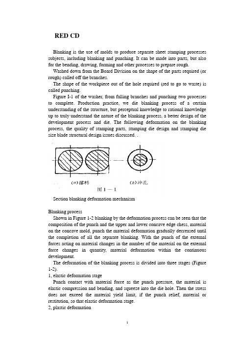
RED CDBlanking is the use of molds to produce separate sheet stamping processes subjects, including blanking and punching. It can be made into parts, but also for the bending, drawing, forming and other processes to prepare rough. Washed down from the Board Division on the shape of the parts required (or rough) called off the branches.The shape of the workpiece out of the hole required (red to go to waste) is called punching.Figure I-1 of the washer, from falling branches and punching two processes to complete. Production practice, we die blanking process of a certain understanding of the structure, but perceptual knowledge to rational knowledge up to truly understand the nature of the blanking process, a better design of the development process and die. The following deformation on the blanking process, the quality of stamping parts, stamping die design and stamping die size blade structural design issues discussed. .Section blanking deformation mechanismBlanking processShown in Figure 1-2 blanking by the deformation process can be seen that the composition of the punch and the upper and lower concave edge chess, material on the concave mold, punch the material deformation gradually decreased until the completion of all the separate blanking. With the punch of the external forces acting on material changes in the number of the material on the external force changes in quantity, material deformation within the continuous development.The deformation of the blanking process is divided into three stages (Figure 1-2).1, elastic deformation stagePunch contact with material force as the punch pressure, the material is elastic compression and bending, and squeeze into the die hole. Then the stress does not exceed the material yield limit, if the punch relief, material or restitution, so that elastic deformation stage.2, plastic deformationPunch to pressure, the stress reaches the yield limit of material, some metal is squeezed into the die hole, producing plastic shear deformation, are shining maggot cut surface. For convex, concave feel there is room between the depression, it is the plastic shear deformation is also accompanied by the bending and stretching.3, fault isolation stageMaterials continue to increase external and internal stress increasing, convex, because the incision die stress concentration, shear strength over the first internal stress, micro-crack appears. Mold continuing under pressure, convex, concave mold cavities of the micro-crack edge to the material constantly within the share capital, then pulled off material separation. Such as convex, concave die gap was reasonable, the upper and lower crack coincide with each other. ' Stress and strainFurther analysis of blanking time of stress and strain state of deformation zone and help to the understanding of the blanking process. Die and punch in the edge of the joint line to take 'cell body, "whose stress-strain diagram shown in Figure 1-3. Can be seen from the figure, it seemsMetal fracture line AB that is cutting edge on-line) at 45 degrees. The main uranium direction I was pulling stress and tensile deformation, tensile stress the goldIs a fiber elongation; its vertical axis 2 is the compression stress direction and compressive deformation, the fiber extrusion pressure; in the tangential direction of the stress and strain is very small, negligible; and principal stress direction at 45. Direction to the direction of maximum shear stress between the punch and die clearance, elongation and tear off the metal, resulting in broken fracture surface roughness, and with a burr.The process can also blanking blanking force deformation curves of the figure is confirmed. Figure 2-9 (materials), is punching a 3 mm thick material punching power and punch of the curve. Can be seen from the diagram:In the process of blanking blanking force size is constantly changing. AB section of the equivalent of punching the elastic deformation stage, BC Section for the plastic deformation stage. When the material internal stress to shear strength began to crack when the material, CD segment for the crack propagation until the material isolated rupture in order teams, DE Dan launch materials introduced die mouth piece.Cut section ofSee Figure 2-10The deformation process of blanking the red plant parts are not smooth vertical section, the section has three areas, namely, with rounded corners, bright band and the fault zone.Rounded band is in the process of blanking the beginning of plastic deformation. Since the bending and stretching metal fibers formed, soft material than hard Branch rounded large.Light zone is the second phase of deformation produced plastic shear deformation of metal forming, has a smooth vertical surface, bright band of the entire cross section of 1 / 2 to 1 / 3 of the light bandwidth of soft materials, hard materials with a narrow bright . With the mechanical properties of materials, space, mold structural changes.Fault is equivalent to the third stage of the blanking process, mainly due to the role of tensile stress, the continuous expansion of China cracks down payments second fiber extension, so a very rough surface is not smooth, and there Liaoduo. In the section on the same punch with these characteristics, but the distribution of the three regions opposite position and blanking.Blanking addition to drag a section of rough dimensions, there are points dome curved, not flat, face a burr, so blanking requirements apply only to an Blanking.Section Drawing gapBlanking time requires not only the shape of call times out of line drawing parts, there should be a certain quality requirements, quality of stamping pieces is cut surface quality, dimensional accuracy and form error. Cut surface should be flat, smooth, no crack and tear, mezzanine and other defects, glitches small parts, the surface should be flat as possible, that is a small vaulted arch, size, degree of precision required to ensure the drawings do not exceed the tolerance range.Factors that affect the quality of stamping pieces range from the actual production that, convex, concave die gap size and power uniformity, pattern edge state, the mold structure and manufacturing precision, quality materials, and so on all affect Na blanking. However, we must find out which plays a decisive role in the quality of the blanking factor. Gap is a.Section 1 on the quality of blankingComparison of straight, smooth, and no burr. In this case, the quality of parts that is a good cross section.When the gap is too hours of up and down the crack does not coincide with each other. . . .When the gap is too large cracks do not overlap. . . . (See 2-11)If the gap uneven distribution of local spikes. . . Uneven wear, increased, so clearance is not only to use reasonable and die on the manufacture and adjustment of space even when the guarantee.2. Gap on the Dimensional AccuracyBlanking Stamping dimensional accuracy refers to the actual size and nominal size of the margin, the difference is smaller the higher the precision.difference between living in two areas packet error, one blanking punch or die with the size of the deviation, one mold itself create bias.Blanking and convex, die size deviation was mainly due to:Workpiece (waste) from the concave mold release, as caused by elastic recovery. Deviation may be positive, it could be negative.Factors affecting the value of this deviation are:1, convex, concave mold gap. Big gap. . . Tensile obvious effect, elastic recovery materials and parts to drop less than the die size, punching pieces. . Small gap. . .2, material properties. Material properties and dimensional accuracy of packages since it will then determine the material properties of its material form in the amount of blanking. Outline of the elastic deformation of the soft small amount of elastic recovery after blanking also small, so the workpiece accuracy. Hard steel elastic recovery greater precision on the lower parts.3, workpiece shape and size. Workpiece thickness and shape of post degree only-J also have an impact, thin elastic recovery of material punching shield large,-t pieces of low accuracy. The more complex the shape of the workpiece, die and create and adjust the gap when the more difficult to ensure uniform, so the greater the size of deviations.See Figure 2-134. Blade-like quality video straight to the section noon5. Gap on the impact of blanking forceThe smaller the gap, blanking deformation area of the higher hydrostatic pressure, the greater the material change Kang force. Blanking force, the greater the contrary, when the gap increases, lower resistance, blanking force alsodecreases, but the value is not reduced (see Figure 2-14)Life on the sidelines of the impact of mold (see materials abbreviated talk)Section III to determine clearance punch and dieThus, convex and concave clearance on blanking die quality morning, punching power, tool life has a great impact, so the mold design - will select a reasonable gap to ensure Blanking section of good quality punching required is small, high-die life. But the difference of quality, precision, blanking force requirements in many aspects of cooperation were identified gap is not limited to the same - a value, but close to each other, taking into account the deviationof model county manufacturing and use of wear and tear,Therefore, production is often to select an appropriate range of reasonable space, as long as the gap falls within this range can be out of good parts, the scope of the minimum value, said minimum clearance Zmin reasonably small. Most reasonable position that the biggest gap Zmax. At least a reasonable gap Z Mi n can be with the board perpendicular to the section, without a significant glitch. In the largest gap Zmax "section can still be satisfied with the quality: just not with the board vertical. Taking into account the die wear and tear during use to increase the gap, so when the design and manufacture a new model to use the smallest reasonable space ZminReasonable methods to determine gap calculated with the experience to determine and French.One theory to define the lawTheory to define the main basis for the law is to ensure that cracks coincide in order to get a good cross section. Group 1 began the process of blanking the instantaneous crack q triangles from the graph we can find space z AB cType in: A, - convex molded into the depth; β - the maximum shear stress direction and the angle between the vertical;Can be seen from the above formula, gap z and the material thickness t, the relative cut into the depth h. / T and the crack orientation day. Relevant, but to another with the material properties and β is related to the more rigid material, h. / T smaller. Therefore, we can see from the style, the main factors affecting thevalue gap is the material properties and thickness. The more rigid material more thick, the necessary and reasonable value of the larger gap. Table 1-3 for the popular press materials, h. / T and β approximation.A variety of materials h. / T and β value is still no accurate determination of value, and. Production is not convenient to use this method, so widely used empirical formula with the graph method.Second, the experience to determine methodsExperience to determine the nature of law is based on the material and thickness, press-type to determineThe formula: K-factor related with the material properties. t - thickness ofmaterial.Soft materials such as 08, l0, brass, copper Z = (0.08-0.1) tIn hardwood Section: A3, A 4,20,25. Z = (0.1-0.I 2) tHard materials such as A5, 50 ... ... and so Z = (0.1-0.14) tLower limit of thin materials which take.Third, the chart methodIn addition, you can directly determine the space look-up table values (such as teaching materials 2-3,2-4,2-5 table) Table 2-5 is the former Ministry of Machinery Industry, "blanking clearance," Technical Guidance Document (JB/z271-86 ) recommended clearance value.Over the past China's general information on using Soviet gap value, from the use of the experience, the gap value is generally small. One reason for this is the classification space is not used according to the characteristics of production, the other is only as the main basis for precision stamping parts, without considering the King and the chess section with a life of quality and other important factors, so many problems exist in production. For example: Wear + blanking force. . .Therefore, in practice, in addition to special requirements of the workpiece outside the vertical section, as far as possible large gap.In addition, my experience in practice should:(1) z-punching to take the value of bigger than expected drop.(2) red holes get bigger when the z value, to prevent broken punch.(3) Carbide Die z value should be 30% larger than the steel.(4)J die orifice is cone-shaped than straight smaller z value.(5) high-speed stamping dies easily when the heat, f value should get bigger.(6) when the punch and die wall thin. To prevent cracking up, should be enlarged punching z.IV Size Calculation of Cutting EdgeDie edge dimensions and tolerances directly affect the dimensional accuracy of Blanking, also is sufficient to guarantee a reasonable gap. Therefore, the correct calculation of the mold edge mold design dimensions and tolerances are small - the work of great importance.Dimensions and tolerances in calculating the cutting edge should follow the following principles:1. Taking into account the drop size depends on the materials and parts die size, while punching pieces depends on the size of the punch dimensions of the blanking die design should be to die as the base is difficult to stay in the punch on the gap; Design Punching model should be based on the punch as the base, orange on the gap left in the concave. (There is a taper section, and the big end blanking parts die size = size, empty pieces of red punch small end size = size)2. Taking into account the wear and tear will foot a larger die, the punch size decreases, in order to ensure the life of mold, the basic blanking die size should be taken close to or equal to the minimum limit of size of the workpiece; Piercing Punch basic dimensions shall be taken as close to the or equal to the maximum limit of size of workpiece, using the smallest reasonable gap value.3. Sampling edge of manufacturing tolerances, the workpiece should be to ensure the accuracy and timeliness based clearance requirements. At the same time easy to mold manufacturing tolerance is too large, then out of the parts may be disqualified, or one can guarantee a reasonable gap; too small. And to die is difficult to mold manufacturing costs.Accuracy and precision blanking dies relationship tableSpecial Note: If the size of the workpiece is not marked tolerance. I T14 without tolerances according to class to deal with, and die according to I D 11 manufacturing (non-graphic parts). Or by I T 6-7 class manufacturing (for round parts).Mold processing method according to the different calculation methods aredivided into two kinds of edge1. Separate punch and die machiningSeparate processing: refers to the punch and die are processed separately by the respective drawings, mold the size of the gap processed by guarantee. Therefore, to calculate and mark out the punch and die dimensions and tolerances. This method is suitable for round or shape of a simple piece.(1) Blanking Die Blanking piece size based degree d, according to the above principles, first determine the small scale and then reduce the die size in order to ensure a reasonable punch clearance. Knife-edge part of the incidence graph of the size shown.Edge blanking die size is calculated as follows:(2) The punching die set punching size of d. (Standard tolerance) calculated according to the principles of the punch first determine the size. Further increasing the die size in order to ensure a reasonable minimum edge clearance associated with some of the dimensions in Figure 2-13 (b) below.Red edge aperture size is calculated as follows:Symbol meaning:X-tolerance zone offset factor, the purpose is to avoid all bias limit most blanking size (other omitted)Its value and accuracy of the workpiece.Tolerance band offset coefficient of 2-7 x to be investigated, or obtained by the following relationsWorkpiece accuracy of IT10 above: x = 1Workpiece accuracy of IT11 ~ 13: x = 1.75Fine piece head IT14: x = 0.5In order to ensure a reasonable space, mold manufacturing tolerances must meet the following conditionsConvex, concave mold separate processing advantages are: convex, concavemold with interchangeable, easy to mold batch processing.Convex, concave mold separate processing disadvantage: in order to ensure a reasonable gap. Require higher levels of mold manufacturing tolerances, mold making more difficult.(Based on the use of examples to explain -6,2-7 table)2. Punch and die with the processingFor complex shapes or thin material workpiece. In order to facilitate mold, should be used with the process. This method is first processed basis documents (when blanking die, punch when the punch), and then base the actual size of the Huai items to do with the other documents (when blanking punch, punch when punch), and then base the actual size of the Huai items to do with the other documents (when blanking punch, punch die when), in another space on the revised smallest reasonable value. Therefore, when used with the process, simply reference documents marked size and tolerance, another mark only basic dimensions. And marked "punch-foot small scale only by the actual preparation of the die to ensure the single gap" (blanking time); or "die size of the actual size of the preparation by the punch to ensure the side gap.." (When punching ). With the process, the base parts of the manufacturing tolerance 6f (or long) is no longer limited by the gap value, or even appropriate to enlarge manufacturing tolerances, so relatively easy to manufacture molds. Most factories have recently used this combined approach. Benchmark parts manufacturing tolerances generally preferable to A / 4For some the shape of complex stamping parts. For each part of the size of the different nature of the wear law is different, it must be a specific analysis. Calculated separately.Figure 2-20a for the blanking parts and die size ,2-20b for the punching pieces and punch size, in these two diagrams: A class size is worn larger size, such size should be charged formula feed die size (2 • 2) calculation, B Class size is worn by people of such small size scale should be punching punch size formula (2-4) calculation; C Class size is worn the same size, of such size, the size of the workpiece in the middle of the basic dimensions as the mold, and then standard deviation can be symmetrical, the specific formula as follows:V blanking forceCutting edge technology, including separation of materials needed forpunching power and discharge power, pushing pieces of power and top pieces of power. After blanking. Washed down the workpiece (or waste) as elastic recovery and expansion will be within the infarct in the die hole. Similarly, the scrap piece〕〔or out of the hole on the elastic contraction because of tight coupling on the punch. ? Called the discharge power;? Named top material (pieces) force;? Called push material (pieces of) force.The purpose of calculating power stamping process is it?Reasonable choice is to press tonnage. (Of course choose not to consider the tonnage presses, as well as tables, press structure... Shut height, etc.) Select press when you press and public pressure (N) must make a big or equal to the total pressure during blankingFirst, the calculation of punching forceFlat blade used in production Die Blanking, the blanking force can be calculated as follows;K-safety factor, and generally the skin = 1.3. It takes into account mold edge wear and blunting the punch and the die gap is uneven material thickness deviation of the performance factors, such as Ko.Blanking of high strength material or thick material and large size parts, the need to force a larger punch. If the blanking press more than the tonnage of the existing plant, it is necessary to reduce the blanking force.1. Heating blankingMaterial shear strength in the heated state decreased significantly, which can reduce the blanking force. However, heating the material will produce oxide, will be deformation, therefore applied only to thick or the surface quality and precision of less demanding jobs. Lower τ2. Ladder arrangement blanking punchIn the multi-blanking punch in the punch made of different degrees south, a ladder Boubou set (Figure 2-18), will enable each punch the maximum blanking force of wood come together. Thereby reducing the total blanking force. Punch height difference between the thickness determined by: t <3mm, h = tt> 3mm h = 0.5tWhen the punch by step layout 'symmetrically as possible. At the same time should do a small punch shorter, longer doing big punch, so to avoid a small punch side material flow because the pressure caused by tilt or break situation.3. Oblique incision Die Blanking Figure 2-u-shaped cloth ladder A model aimed Knife-edge blanking level, the entire flat edge on the contact sheet to the rather oblique knife edge blanking die, because edge is inclined, not simultaneously cut into the knife-edge blanking time, but gradually punching material, so very dry by punching a small section of the post. Thus lower. Second, the calculation of other blanking forceMany factors affect these forces, mainly the mechanical properties and thickness, die gap, the workpiece shape and size and lubrication conditions. The effects of these factors is very complex to quantify accurately reflect the size of these forces is difficult. Therefore, the general experience with the following formula:Fx = KF (K look-up table 2-10)The overall strength based on the actual die stamping process concrete analysis of the structure.外文资料译文冲裁冲裁是利用模具使板科产生分离的冲压工序,包括落料与冲孔。
中国地质大学长城学院本科毕业论文外文资料翻译系别:工程技术系专业:机械设计制造及其自动化姓名:王逸君学号:052116312015年03月20日中国的模具和模具工业技术的发展摘要近年来,模具工业和技术已在中国快速发展, 尤其是冲压模具、塑料模具、模具CAD/CAE/ CAM,快速原型和快速模具制造领域和其他一些特殊的技术。
在本文中,所有这些领域的改进和模具技术也进行了简要的总结,根据分析和总结,本文还指出了发展的前景和目标是为了满足当前和未来在中国市场的需求。
关键词:模具工业和技术;快速原型和快速模具制造;发展前景1.中国模具工业的现状自1980,模具工业已在中国发展很快,国民经济的高速发展也对模具工业提出了更高的要求。
近年来,在中国生产模具行业增幅约15% 。
目前,中国拥有17000多家模具生产工厂,1998年大约500000的人关注这个领域,中国模具行业总产量达到245亿元人民币。
模具行业中,冲压模具占50%,塑料模具占33%,压铸模具约占6%与其他模具约11%。
由于开放政策的实施,模具工业企业的所有权已经发生了显著的变化。
不仅只与国有企业和私营企业,除了国有专业模具厂,还有许多模具厂不同所有制,如合资企业,,他们都发展很快。
此外,集体和民营企业在广东和浙江两省很受欢迎,例如,有在浙江省黄岩地区有数百家模具制造集体和民营企业,这就是中国著名的“土地模具”。
在广东省,为了提高产品竞争力一些大集团公司和其他新出现的乡镇企业投入大量资金用于模具制造业。
例如,包括科龙,美的,康佳和威力等在内的许多公司,建立了自己的模具制造中心。
此外,这些模具厂拥有先进的设备和高素质、高水平的技术人员。
此外,先进的CAD/CAM技术,电火花加工技术,热流道和气体辅助注射技术在这些工厂采用。
到目前为止,有数以千计的合资企业,专门为模具制造自己的投资的外资企业,都分布在经济发达地区沿海岸。
例如,无锡微研有限公司。
在江苏有超过200名员工,是一个日本的企业。
毕业设计外文文献翻译题目(中文)冲压成型(英文)Stamping becomes typ 学生姓名张皓完成日期:2011 年03 月12 日目录1.冲压成型作者:STEPHENS2.材料特性作者:MARK JAFEStamping becomes typThe confidence level in successfully forming a sheetmetal stamping increases as the simplicity of the part’s topography increases. The goal of forming with stamping technologies is to produce stampings with complex geometric surfaces that are dimensionally accurate and repeatable with a certain strain distribution, yet free from wrinkles and splits. Stampings have one or more forming modes that create the desired geometries. These modes are bending, stretch forming and drawing. Stretching the sheetmetal forms depressions or embossments. Drawing compresses material circumferentially to create stampings such as beer cans.As the surfaces of the stamping become more complex, more than one mode of forming will be required. In fact, many stampings have bend, stretch and draw features produced in the form die. The common types of dies that shape material are solid form, stretch form and draw.Solid FormThe most basic type of die used to shape material is the solid form die. This tool simply displaces material via a solid punch “crashing”the material into a solid die steel on the press downstroke. The result is a stamping with uncontrolled material flow in terms of strain distribution. Since “loose metal”is present on the stamping, caused by uncontrolled material flow, the part tends to be dimensionally and structurally unstable.Stretch FormForming operations that provide for material flow control do so with a blankholder. The blankholder is a pressurized device that is guided and retained within the die set. Stampings formed with a blankholder may be described as having three parts, shown in Fig. 1. They are the product surface(shown in red), blankholder surface (flat area shown in blue) and a wall that bridges the two together. The theoretical corner on the wall at the punch is called the punch break. The punch opening is the theoretical intersection at the bottom of the draw wall with the blankholder. The male punch is housed inside the punch opening, whereas the blankholder is located around the punch outside the punch opening. These tools have a one-piece upper member that contacts both the blankholder and punch surfaces. A blank or strip of material is fed onto the blankholder and into location gauges. On the press downstroke, the upper die member contacts the sheet and forms a lock step or bead around the outsideperimeter of the punch opening on the blankholder surface to prevent material flow off the blankholder into the punch. The blankholder then begins to collapse and material stretches and compresses until it takes the shape of the lower punch. The die actions reverse on the press upstroke, and the formed stamping is removed from the die.DrawThe draw die has earned its name not from the mode of deformation, but from the fact that the material runs in or draws off the blankholder surface and into the punch. Although the draw mode of deformation is present in draw dies, some degree of the stretch forming and bending modes generally also are present. The architecture and operational sequence for draw dies is the same as stretch-form dies with one exception. Material flow off the blankholder in draw dies needs to be restrained more in some areas than others to prevent wrinkling. This is achieved by forming halfmoon-shaped beads instead of lock steps or beads found in stretch-form dies.The first stage of drawing sheetmetal,after the blank or strip stock has been loaded into the die, is initial contact of the die steel with the blank and blankholder. The blank, round for cylindrical shells to allow for a circumferential reduction in diameter, is firmly gripped all around its perimeter prior to any material flow. As the press ram continues downward the sheetmetal bends over the die radius and around the punch radius. The sheetmetal begins to conform to the geometry of the punch.Very little movement or compression at the blank edge has occurred to this point in the drawing operation. Air trapped in the pockets on the die steel is released on the press downstroke through air vents.The die radius should be between four and 10 times sheet thickness to prevent wrinkles and splits.Straightening of sheetmetal occurs next as the die continues to close. Material that was bent over the die radius is straightened to form the draw wall. Material on the blankholder now is fed into the cavity and bent over the die radius to allow for straightening without fracture. The die radius should be between four and 10 times sheet thickness to prevent wrinkles and splits. The compressive feeding or pulling of the blank circumferentially toward the punch and die cavity is called drawing. The draw action involves friction, compression and tension. Enough force must be present in drawing to overcome the static friction between the blank and blankholder surfaces. Additional force is necessary during the drawing stage toovercome sliding or dynamic friction and to bend and unbend the sheet from the blankholder surface to the draw wall. As the blank is drawn into the punch, the sheetmetal bends around the die radius and straightens at the draw wall.To allow for the flow of material, the blank is compressed. Compressionincreases away from the die radius in the direction of material flow because there is more surface area of sheetmetal to be squeezed. Consequently, the material on the blankholder surface becomes thicker.The tension causes the draw wall to become thinner. In some cases, the tension causes the draw wall to curl or bow outward. The thinnest area of the sheet is at the punch radius, and gradually tapers thicker from the shock line to the die radius. This is a probable failure site because the material on the punch has been work-hardened the least, making it weaker than the strain hardened material. The drawing stage continues until the press is at bottom dead center. With the operation now complete, the die opens and the blankholder travels upward to strip the drawn stamping off of the punch. Air vents provided in flat or female cavities of the punch allow air to travel under the material as it is lifted by the blankholder. The stamping will have a tendency to turn inside out due to vacuum in the absenceof air vents.冲压成型译文:板料冲压成形成功机率着冲压件形状的复杂程度减少而增加,冲压成形的目的是生产具有一定尺寸,形状并有稳定一致应力状态,甚至无起皱无裂纹的冲压件.冲压有一种至多种成形方式用来成型所需形状,它们是弯曲,局部成形,拉深,局部成形用来成形,凹陷形状或凸包,拉深用来成形,啤酒罐之类的冲压件,随着冲压件的形状越来越复杂,多种成形方法将会被用到同一零件的成型中,事实上,有很多冲压件上同时有弯曲,局部成型,拉深模具成型的特征,通常有三种形式的模具,它们是自由成型,局部成形以及拉深形式.一自由成形自由成形是用的最基本的一种成形材料的成形模具,这类模具只是简单地通过一个冲头在压力机下行过程中把材料“撞击”进入凹模中成形材料。
j o u r n a l o f m a t e r i a l s p r o c e s s i n g t e c h n o l o g y209(2009)3532–3541j o u r n a l h o m e p a g e:w w w.e l s e v i e r.c o m/l o c a t e/j m a t p r o t ecContact pressure evolution at the die radius in sheet metal stampingMichael P.Pereira a,∗,John L.Duncan b,Wenyi Yan c,Bernard F.Rolfe da Centre for Material and Fibre Innovation,Deakin University,Pigdons Road,Geelong,VIC3217,Australiab Professor Emeritus,The University of Auckland,284Glenmore Road,RD3,Albany0793,New Zealandc Department of Mechanical and Aerospace Engineering,Monash University,Clayton,VIC3800,Australiad School of Engineering and IT,Deakin University,Geelong,VIC3217,Australiaa r t i c l e i n f oArticle history:Received27March2008 Received in revised form 18July2008Accepted17August2008Keywords:Contact pressureSheet metal stamping Tool wearBending-under-tension a b s t r a c tThe contact conditions at the die radius are of primary importance to the wear response for many sheet metal forming processes.In particular,a detailed understanding of the con-tact pressure at the wearing interface is essential for the application of representative wear tests,the use of wear resistant materials and coatings,the development of suitable wear models,and for the ultimate goal of predicting tool life.However,there is a lack of infor-mation concerning the time-dependant nature of the contact pressure response in sheet metal stamping.This work provides a qualitative description of the evolution and distribu-tion of contact pressure at the die radius for a typical channel forming process.Through an analysis of the deformation conditions,contact phenomena and underlying mechanics, it was identified that three distinct phases exist.Significantly,the initial and intermediate stages resulted in severe and localised contact conditions,with contact pressures signif-icantly greater than the blank material yield strength.Thefinal phase corresponds to a larger contact area,with steady and smaller contact pressures.The proposed contact pres-sure behaviour was compared to other results available in the literature and also discussed with respect to tool wear.©2008Elsevier B.V.All rights reserved.1.IntroductionIn recent years,there has been an increase in wear-related problems associated with the die radius of automotive sheet metal forming tools(Sandberg et al.,2004).These problems have mainly been a consequence of the implementation of higher strength steels to meet crash requirements,and the reduced use of lubricants owing to environmental concerns. As a result,forming tools,and the die radii in particular, are required to withstand higher forming forces and more severe tribological stresses.This can result in high costs due∗Corresponding author.Tel.:+61352273353;fax:+61352271103.E-mail address:michael.pereira@.au(M.P.Pereira).to unscheduled stoppages and maintenance,and lead to poor part quality in terms of surfacefinish,geometric accuracy and possible part failure.If the side-wall of a part is examined after forming,a demarcation known as the‘die impact line’is easily visible (Karima,1994).This line separates the burnished material that has travelled over the die radius and the free surface that has not contacted the tooling,clearly indicating that severe sur-face effects exist at the die radius.It is therefore important to understand the contact phenomena at this location of the tooling.0924-0136/$–see front matter©2008Elsevier B.V.All rights reserved. doi:10.1016/j.jmatprotec.2008.08.010j o u r n a l o f m a t e r i a l s p r o c e s s i n g t e c h n o l o g y 209(2009)3532–354135331.1.Bending-under-tension testThe bending-under-tension test –in which a strip is bent over a cylindrical tool surface and pulled against a speci-fied back tension –has been used in the laboratory for many years to simulate conditions at the die radius (Ranta-Eskola et al.,1982).The literature contains numerous experimental investigations that examine surface degradation over the die radius after repeated or continuous bending-under-tension operations.For example,in independent studies with differ-ing test conditions and materials,Mortensen et al.(1994),Hortig and Schmoeckel (2001)and Attaf et al.(2002),each visu-ally observed wear in two localised regions on the die radius.More detailed examination of the worn die radius surface,through measurement of surface roughness (Christiansen and De Chiffre,1997),determination of wear depth (Eriksen,1997)and scanning electron microscope imaging (Boher et al.,2005),has also confirmed the existence of similar localised wear regions.In addition to the experimental analyses,Mortensen et al.(1994),Hortig and Schmoeckel (2001)and Attaf et al.(2002),each conducted finite element analyses of the bending-under-tension process.In all cases,the finite ele-ment models predicted the existence of distinct contact pressure peaks on the die radius surface,correlating well with the regions of localised ing in situ sensors Hanaki and Kato (1984)and more recently Coubrough et al.(2002)experimentally demonstrated that similar contact pressure peaks exist at locations on the die radius near the entry and exit of the strip during the bending-under-tension test.It is evident that despite covering a wide range of die materials (both coated and un-coated),lubrication,surface roughness,bend ratio and work-piece materials,each of thestudies discussed in the preceding paragraphs were found to exhibit similar characteristic two-peak contact pressure distributions and localised regions of wear over the die radius.These results,and the documented power law rela-tion between wear and normal load for sliding contacts (Rhee,1970),indicate that contact pressure is of primary significance to the wear response.1.2.Sheet metal stampingThe contact conditions occurring during sheet metal stamping operations have not been studied as extensively as those of the bending-under-tension process.Through finite element anal-yses of axisymmetric cup-drawing processes,Mortensen et al.(1994)and Jensen et al.(1998)identified that time-dependant contact conditions occur at the die radius,as opposed to the ‘stationary’conditions of the bending-under-tension test (Hortig and Schmoeckel,2001).In recent numerical studies on a plane strain channel forming process,Pereira et al.(2007,2008)also reported time-dependant plex contact conditions over the die radius were found to occur,with regions of highly localised and severe contact pressure.Selected results of the finite element analysis by Pereira et al.(2008)are given in Fig.1,where the dynamic nature of the con-tact pressure distribution can be seen.Additionally,the Mises stress contours show the corresponding deformation of the blank and provide an indication of where yielding occurs.Although each of the above investigations report time-dependant contact conditions for sheet metal stamping processes,the authors in each case provide little explanation into the reasons for the identified contact behaviour.Further analysis of this phenomenon has not been found in the liter-ature.Fig.1–Mises stress contours and normalised contact pressure distributions predicted by finite element analysis at the three distinct stages during a channel forming process (see Section 4.1for more details).The regions in white in the Mises contours indicate values of stress below the blank material initial yield strength.3534j o u r n a l o f m a t e r i a l s p r o c e s s i n g t e c h n o l o g y209(2009)3532–3541 1.3.MotivationIn order to understand tool wear in sheet metal stamp-ing,or to use representative tests(bending-under-tension,slider-on-sheet,etc.)to characterise the wear response of toolmaterials and coatings,knowledge of the local contact condi-tions that occur during the stamping operation is essential.Asdiscussed,the contact pressure is of particular significance.However,a description of the evolution and distribution ofcontact stresses experienced by sheet metal forming tool-ing,including an explanation for this behaviour,has not beenfound in the literature.In this work,a qualitative description of the contact pres-sure evolution at the die radius and the associated stressdistributions in the blank during a channel forming processis given.The description is based on experimental observa-tions and the results offinite element analyses.Through ananalysis of the deformation conditions,contact phenomenaand underlying mechanics,it will be shown that three dis-tinct phases exist.Due to the unique deformation and contactconditions that are found to occur,the initial and intermedi-ate stages exhibit localised regions of severe contact pressure,with peak contact stresses that are significantly greater thanthe blank material yield strength.Thefinal stage,which canbe considered as steady state with regards to the conditions atthe die radius,corresponds to a larger contact area with stableand smaller contact pressures.It is noted that the magnitude of the contact stress peakswill depend on variables such as back tension on the sheet,thedie radius to sheet thickness ratio,and the clearance betweenthe punch and die.These effects are not investigated in thiswork.The objective of this work is to provide an understandingof an important aspect of sheet metal forming,rather thana quantitative analysis of a specific case.This should assistin understanding die wear,which is an increasing problemwith the implementation of higher strength sheet in stampedautomotive components.2.The sheet metal stamping processThe stamping or draw die process is shown schematically inFig.2.Sheet metal is clamped between the die and blank-holder and stretched over the punch.The sheet slides overthe die radius surface with high velocity in the presence ofcontact pressure and friction,as it undergoes complex bend-ing,thinning and straightening deformation(Fig.2c).In themost rudimentary analysis of sheet metal forming,bending isneglected and the deformation is studied under the action ofprincipal tensions(Marciniak et al.,2002).The tension is theforce per unit width transmitted in the sheet and is a prod-uct of stress and thickness.For two-dimensional plane straindeformation around the die radius,the well-known analysisindicates that the contact pressure p isp=TR=1R/t(1)where 1is the longitudinal principal stress,T is the longitu-dinal tension,R is the die radius,t is the sheet thickness,and Fig.2–(a)The beginning of a typical sheet metal stamping process.(b)The motion and forces exerted by the tools cause the blank to be formed into a channel shape during the stamping process.(c)Forces acting on the sheet at the die radius region.R/t the bend ratio.Due to the effect of friction,the longitudinal tension in the sheet varies along the die radius.If the tension at one point,j,on the die radius is known,then the tension at some other point,k,further along the radius can be found according to:T k=T j exp( Âjk)(2)whereÂjk is the angle turned through between the two points, and is the coefficient of friction between the tool and sheet surfaces.j o u r n a l o f m a t e r i a l s p r o c e s s i n g t e c h n o l o g y209(2009)3532–35413535Eq.(1)provides a useful relationship that shows the contactpressure is inversely proportional to the bend ratio.Given thatthe tension is usually close to the yield tension and that thebend ratio in typical tooling is often less than10,Eq.(1)indi-cates that the contact stress is an appreciable fraction of theyield stress.This implies that the assumption of plane stressin the strip may not be valid.Additionally,a numerical studyof a bending-under-tension process with a bend ratio of3.3revealed that the restraint forces attributed to bending(andunbending)were almost50%of the total restraint forces onthe sheet(Groche and Nitzsche,2006).Although Eqs.(1)and(2)can be modified to include the work done in bending andstraightening,these simple models are unlikely to adequatelydescribe the contact pressure distribution.Furthermore,such an analysis assumes that the sheetslides continuously over the die radius under steady-state-type conditions analogous to a bending-under-tensionprocess.However,as discussed in Section1,several studies inthe literature have shown that the contact conditions are notsteady during typical sheet metal stamping.For these reasons,it is evident that a more detailed analysis,including examina-tion of the stress states and yielding in the sheet,is required inorder to understand the complex and time-dependant contactconditions at the die radius.3.Contact pressure at the die radiusIn this work,a qualitative description of the developmentof peak contact pressures at the die radius for the channelforming process shown in Fig.2is given.For simplicity,thedeformation of the sheet is considered as a two-dimensional,plane strain process.A linear-elastic,perfectly plastic sheetmaterial model,obeying a Tresca yield criterion is used.Thematerial curve is shown in Fig.3,where theflow stress is S,with zero Bauschinger effect on reverse loading.It is assumedthat if there is a draw-bead,it is at some distance from the dieradius so that the sheet entering the die radius is undeformedbut has some tension applied.In this study,the deformation and contact conditions at thedie radius for a typical sheet metal forming process are dividedinto three distinct phases(Fig.4).A material element on theblank,Point A,is initially located at the beginning of the dieradius,as shown in Fig.4a.At this instant,contact islimitedFig.3–Simplified plane strain material response with reverseloading.Fig.4–Three distinct phases of deformation and contact, which occur during the channel forming process:(a)initial deformation,(b)intermediate conditions,and(c)steady-state conditions at die radius.to a line across the die radius.During the next stage,Point A has travelled around the die radius,but has not yet reached the exit or tangent point(Fig.4b).At this instant,the material in the side-wall(between the die radius and punch radius) remains straight and has not previously contacted the tools.A state of approximately steady conditions at the die radius is reached in Fig.4c,where Point A is now in the side-wall region.3.1.Initial deformationAt the start of the forming stroke,contact between the blank and die occurs near the start of the die radius at an angle of Â=˛,as shown in Fig.5a.The Mohr circle of stress at the con-tacting inner surface and the stress distribution through the thickness of the sheet are given schematically in this diagram. The regions of plastic deformation in the sheet are indicated by shading.The sheet is bent by the transverse force F shown,so that a compressive bending stress 1exists on the upper surface.Due to the initial lack of conformance of the blank to the radius, contact occurs almost along a line,resulting in a contact pres-sure P˛that can be very high.As a result,the normal stress 3, which is equal to−P˛,is greatest at the surface and diminishes to zero at the outer,free surface.At this location,approx-3536j o u r n a l o f m a t e r i a l s p r o c e s s i n g t e c h n o l o g y 209(2009)3532–3541Fig.5–(a)Schematic of the blank to die radius interface during the initial deformation stage—the stress distribution through the thickness and the Mohr’s circle at the surface of the contact zone are shown.Corresponding distributions around the die radius of (b)contact pressure and (c)bending moment in the sheet.imately plane stress conditions exist and the sheet yields under tension at the plane strain yield stress S .The transverse stress 2at the inner surface will have an intermediate value,since the process is plane strain.In the plastic case,this is the mean of the other principal stresses.In the elastic case,this is only approximately so.The bending stress and contact pressure at the inner sur-face generate a high compressive hydrostatic stress,such that yielding can be suppressed (the diameter of the Mohr circle is <S ).This phenomenon is supported by the finite element simulation results of the case study shown in Fig.1a.The bending moment m is greatest at the contact line,as shown in Fig.5c;yet plastic bending only takes place either side of thisregion,where the inhibiting compressive hydrostatic stress is lower.The result is that a very high-pressure peak occurs at the contact line,greater in magnitude than the sheet yield stress (Fig.5b).This initial line contact,causing a localised peak contact pressure,is a momentary event.3.2.Intermediate conditionsAs the punch draws the sheet to slide into the die cavity,Point A moves away from the start of the radius,as shown in Fig.6a.Due to the plastic bending of the sheet that occurs near the beginning of the die radius,in the vicinity of Â=0◦,the mate-rial entering the die radius has greater conformance with thej o u r n a l o f m a t e r i a l s p r o c e s s i n g t e c h n o l o g y209(2009)3532–35413537Fig.6–(a)Schematic of the blank to die radius interface during the intermediate conditions—the stress distribution through the thickness and the Mohr’s circle at the surface of the contact zones are shown.Corresponding distributions around the die radius of(b)contact pressure and(c)bending moment in the sheet.die radius surface.This causes a reduction in contact pressure, due to the change from line contact in Fig.5to a broader con-tact area in Fig.6.Consequently,the compressive hydrostatic stress is reduced and plastic deformation at the blank surface occurs(the diameter of the Mohr circle is S).The bending moment on the sheet is greatest near the Point A,as shown in Fig.6c,such that the strip may be over-bent at this point,causing a loss of contact between the sheet and the die radius.A similar effect can exist over the nose of the punch in vee-die bending(Marciniak et al.,2002).As such,a second contact point with the die occurs further along the radius,at Â=ˇ.Point A,which began at the start of the radius,has not yet reached the tangent point atˇ.Hence,the material currently atˇis largely undeformed,despite the fact that the angle of wrap of the blank over the die radius is relatively large.With similar contact conditions to the initial deformation stage,line contact occurs atˇ.As seen previously,these conditions result in high contact pressure,large compressive hydrostatic stress, and can suppress plastic deformation at the blank surface as supported by the case study in Fig.1b.Fig.6b shows the contact pressure distribution for the inter-mediate stage.The magnitude of the contact pressure at the start of the radius is less than the yield stress,where con-tact is distributed over a wider area.Conversely,a sharp peak exists at the tangent point atˇ,where the sheet is still being bent and the contact area is small.In many punch and die3538j o u r n a l o f m a t e r i a l s p r o c e s s i n g t e c h n o l o g y209(2009)3532–3541configurations,the punch displacement needed to draw the material from the beginning of the die radius(Point A in this case)around to the tangent point is significant.Therefore,the intermediate phase may be long and the maximum contact angle,ˇmax,quite large.3.3.Steady-state conditions at the die radiusSteady-state conditions at the die radius are reached when Point A,which began at the start of the die radius,has moved around and become part of the side-wall,as shown in Fig.7a. New material is plastically bent as it enters the die radius from the blank-holder region.Here,the contact pressure and stress distributions are similar to those of the intermediate stage, due to the bending and conformance of the blank to the die radius.Beyond this region,the sheet remains in contact with the die without further plastic deformation,and the resulting contact pressure is small.Further along the radius,under the action of an increasing opposite moment,the sheet is partially straightened,whereFig.7–(a)Schematic of the blank to die radius interface during the steady-state deformation stage—the stress distribution through the thickness and the Mohr’s circle at the surface of the contact zones are shown.The stress distribution through the thickness at two locations in the side-wall region is also shown.Corresponding distributions around the die radius of (b)contact pressure and(c)bending moment in the sheet.j o u r n a l o f m a t e r i a l s p r o c e s s i n g t e c h n o l o g y209(2009)3532–35413539it loses contact with the die radius.A second,smaller con-tact pressure peak occurs at the locationÂ= .This peak can be explained,at least in part,by examining the sim-plified analysis presented in Section2.According to Eq.(1), the contact pressure is proportional to the tension in the sheet—which itself increases with increasing angleÂalong the radius,according to Eq.(2).Therefore,the contact pressure increases with angle along the radius,causing a peak pressure near the sheet exit point,indicated by P in Fig.7b.Here,the sheet unloads elastically and the stress distribution is shown (the diameter of the Mohr circle is<S).Beyond the contact pressure peak,the bending moment on the sheet becomes reversed,as shown in Fig.7c,and straightening begins at the tangent point.The straightening process continues beyond the contact point;the extent of which depends on the tooling conditions and the tension gen-erated by the blank-holder.‘Side-wall curl’is a well-known phenomenon in channel forming and is greatest with smaller blank-holder tension.As a result of the curl in the side-wall,the angle of contact is less than in the intermediate stage,where the entire side-wall was approximately straight. This indicates that there is a region on the die radius that only makes contact with the blank during the intermediate stage—i.e.an intermediate-only contact region.It is worth emphasizing that,despite the approximately steady contact conditions that occur at the die radius during this stage,the forming process itself does not reach a true steady state.This is because the blank continues to experi-ence significant deformation and displacement as it is drawn over the die radius by the action of the moving punch.As a result,there will be a continual reduction in theflange length and a subsequent changing of contact conditions in the blank-holder region.4.DiscussionIn Section3,a qualitative description of the deformation and contact pressure response at the die radius of a sheet metal stamping process was given.This section will discuss the identified response,with particular reference to results from other analyses in the literature,comparison to the bending-under-tension process,and wear at the die radius.4.1.Correlation withfinite element model predictionsIn recent studies,Pereira et al.(2007,2008)usedfinite element analysis to examine the contact pressure at the die radius for a channel forming process.A2mm thick high strength steel blank was formed over an R5mm die radius(R/t=2.5), with a punch stroke of50mm.The contact pressure response predicted by Pereira et al.(2008)was re-plotted at three dis-tinct instances in Fig.1.In thisfigure,the contact pressure is normalised by the constant Y,which can be considered as theflow stress of the blank material if a perfectly plas-tic approximation of the material stress–strain response was adopted(see Marciniak et al.(2002)for an explanation of the approximation method and calculation of Y).As such,the use of the normalised contact pressure allows better comparison between the analysis employing a blank material with con-siderable strain hardening(Fig.1)to that which assumes the blank material has zero strain hardening(Figs.5–7).The normalised contact pressure distributions in Fig.1 clearly demonstrate the existence of the three phases iden-tified in Section3.Notably,thefirst two stages in Section3 correspond to the single transient phase reported in the pre-vious numerical study(Pereira et al.,2008).The discrepancy is caused by the fact that the initial contact stage,which is a momentary event,is easily overlooked without a detailed analysis of the deformation and contact conditions occurring at the die radius.The results by Pereira et al.(2007,2008)verify that the ini-tial and intermediate phases of the process result in the most severe and localised contact loads.Fig.1shows that at the regions of line contact,identified in Sections3.1and3.2,the peak contact pressures are well in excess of Y.In fact,the maximum contact pressure for the entire process was found to occur during the intermediate stage,with a magnitude of approximately3times the material’s initial yield strength (Pereira et al.,2008).Examination of the Mises stress plots in Fig.1at the regions of line contact also confirm the hypothesis of suppressed plasticity due the localised zones of large con-tact pressure,and hence large compressive hydrostatic stress.The results in Fig.1c confirm that the contact pressure is significantly reduced during the steady phase,with the mag-nitude of pressure less than Y due to the increased contact area.Thefinite element results also show that the maximum angles of contact between the blank and die radius during the intermediate and steady phases are approximately80◦and 45◦,respectively(Pereira et al.,2008).This confirms the exis-tence of an intermediate-only contact region,corresponding to the region of45◦<Â≤80◦for the case examined.parison to the bending-under-tension testThe identified steady-state behaviour at the die radius during the stamping process shows numerous similarities to a typical bending-under-tension test.For example,the stress distribu-tions through the thickness of the sheet shown in Fig.7a, compare well to those proposed by Swift(1948),in his analysis of a plastic bending-under-tension process for a rigid,per-fectly plastic strip.Additionally,the angle of contact and shape of contact pressure distributions presented in Figs.7b and1c, show good correlation with the results recorded by Hanaki and Kato(1984)for experimental bending-under-tension tests.The separatefinite element studies of bending-under-tension processes by Hortig and Schmoeckel(2001)and by Boher et al.(2005)also show similarly shaped two-peak contact pressure distributions.The distributions are char-acterised by large and relatively localised pressure peaks at the beginning of the contact zone,with smaller and more distributed secondary peaks at the end of the con-tact zone.Additionally,these investigations each show that the angle of contact is significantly less than the geomet-ric angle of wrap,confirming the existence of the unbending of the blank and curl that occurs in the side-wall region. These attributes of the bending-under-tension test have direct similarities to the contact pressure response predicted by Pereira et al.(2008)and described previously in Section 3.3,despite the obvious differences in materials,processes,3540j o u r n a l o f m a t e r i a l s p r o c e s s i n g t e c h n o l o g y209(2009)3532–3541bend ratios and back tensions considered.Although there are numerous similarities,direct quantitative comparison between the bending-under-tension test and the steady-state phase of the channel forming process cannot be made,due to the differences in the application of the back and forward tensions.4.3.Contradictions withfinite element model predictionsAs stated in Section1,there are a limited number of other investigations in the literature that examine the time-dependant contact pressure response of sheet metal stamping processes.Finite element analyses by Mortensen et al.(1994) and Jensen et al.(1998)predicted that time-dependant contact conditions do occur.However,these results do not show the same trends as presented in this study and shown by Pereira et al.(2007,2008)in previousfinite element investigations. This section will briefly discuss the possible reasons for such discrepancies.Firstly,considering thefinite element analysis of a cup-drawing process by Mortensen et al.(1994),the predicted contact pressure over the die radius was presented at only three distinct intervals during the process.By comparison, Pereira et al.(2008)recorded the contact pressure at approx-imately140intervals throughout thefinite element results history,in order to completely characterise the complex pressure evolution.Therefore,it is likely that the transient effects,which are reported in this study,were not captured by Mortensen et al.(1994)due to the limited number of instances at which the contact pressure was recorded.Thefinite element investigation by Jensen et al.(1998) examined the contact conditions at approximately100inter-vals during a cup-drawing process,but also did not observe a severe and localised transient response,as seen in this study. (Significantly varied and localised contact conditions were observed at the end of the process,but these were identi-fied to be due to the blank-rim effect,and are not relevant to this study.)Close examination of the results by Jensen et al. (1998)show that some localised contact conditions do occur at the beginning of the process—however,these appear rela-tively mild and were not discussed in the text.This reduced severity of the transient response,compared to that predicted by Pereira et al.(2008),can be partly explained by the fact that the actual contact pressure at the die radius was not shown by Jensen et al.(1998).Instead,Z xt,which was defined to be a function of contact pressure and sliding velocity,was used to characterise the contact conditions.This could have effec-tively reduced the appearance of the initial localised contact conditions,due to the slower sliding velocity shown to exist during the initial stage.Additionally,Jensen et al.(1998)used 20finite elements to describe the die radius surface,compared to240elements used by Pereira et al.(2008).The reduced num-ber of elements at the die radius surface can have the effect of averaging the extremely localised contact loads over a larger area,thus reducing the magnitude of the observed contact pressure peaks.Finally,the different processes examined(cup drawing vs.channel forming)may also result in a different transient response.4.4.Relevance to tool wearWear is related to contact pressure through a power law rela-tionship(Rhee,1970).Therefore,the regions of severe contact pressure during the initial and intermediate stages may be particularly relevant to tool wear at the die radius.Thefinite element investigations by Pereira et al.(2007,2008)showed that the maximum contact pressure for the entire process occurs in the intermediate-only contact region,at approximately Â=59◦,indicating that the intermediate stage is likely to be of primary significance to the wear response.This result was val-idated by laboratory-based channel forming wear tests,for the particular case examined(Pereira et al.,2008).However,for each stamping operation,it can be seen that the relative sliding distance between the blank and die radius associated with the initial and intermediate stages is small—i.e.no greater than the arc length of the die radius surface.In comparison,the steady contact pressure phase cor-responds to a much larger sliding distance—i.e.the sliding distance will be approximately in the same order of magnitude as the punch travel.Therefore,despite the smaller contact pressures,it is possible that the steady phase may also influ-ence the tool life;depending on the process conditions used (e.g.materials,surface conditions,sliding speed,lubrication) and the resulting wear mechanisms that occur.The existence of an intermediate-only contact zone(i.e.the region <Â≤ˇmax),is convenient for future wear analyses.Due to the lack of sliding contact in this region during the steady-state phase,any surface degradation of the die radius at angles ofÂ> must be attributed to the intermediate stage of the sheet metal stamping process.Therefore,it is recommended that future wear analysis examine this region to assess the importance of the intermediate contact conditions on the overall tool wear response of the sheet metal stamping pro-cess.The existence of the initial and intermediate stages high-light that the bending-under-tension test,due to its inherently steady nature,is unable to capture the complete contact con-ditions that exists during a typical sheet metal stamping process.Therefore,the applicability of the bending-under-tension test for sheet metal stamping wear simulation may be questionable.5.SummaryIn this work,a qualitative description of the development of peak contact pressures at the die radius for a sheet metal stamping process was given.It was shown that three distinct phases exist:(i)At the start of the process,the blank is bent by the actionof the punch and a high contact pressure peak exists at the start of the die radius.(ii)During the intermediate stage,the region of the sheet that was deformed at the start of the die radius has not reached the side-wall.Therefore,the side-wall remains straight and the arc of contact is a maximum.The largest pressure,which is significantly greater than the sheet materialflow stress,exists towards the end of the die。
模具工业是国民经济的基础工业,是国际上公认的关键工业,工业发达国家称之为“工业之母”。
模具成型具有效率高,质量好,节省原材料,降低产品成本等优点。
采用模具制造产品零件已成为当今工业的重要工艺手段。
模具在机械,电子,轻工,纺织,航空,航天等工业领域里,已成为使用最广泛的工业化生产的主要工艺装备,它承担了这些工业领域中60%--80%产品零件,组件和部件的加工生产。
“模具就是产品质量”,“模具就是经济效益”的观念已被越来越多的人所认识和接受。
在中国,人们已经认识到模具在制造业中的重要基础地位,认识更新换代的速度,新产品的开发能力,进而决定企业的应变能力和市场竞争能力。
在目前用薄钢板制造发动机罩盖的传统还是会持续相当一段时间,所以有必要在钢板的基础上通过利用计算机软件的功能分析零件的工艺性能(结构合理,受力,是否容易冲出破面、、、),发现现有零件的不足之处,讨论并确定改进这些不足之处,进而改善模具的设计,改良冲裁方式;最终实现产品的改良,改善产品的力学性能,外观,使用效果,和造价等等。
冲压加工是通过模具来实现的,从模具角度来看,模具生产技术水平的高低,已成为衡量一个国家产品制造水平高低的重要标志,因为模具在很大程度上决定着产品的质量、效益和新产品的开发能力。
“模具是工业生产的基础工艺装备”也已经取得了共识。
据统计,在电子、汽车、电机、电器、仪器、仪表、家电和通信等产品中,60%~80%的零部件都要依靠模具成形。
用模具生产制件所具备的高精度、高复杂程度、高一致性、高生产率和低消耗,是其他加工制造方法所不能比拟的。
同时,冲压加工也创造了巨大的价值增值,模具是“效益放大器”,用模具生产的最终产品的价值,往往是模具自身价值的几十倍、上百倍。
目前全世界模具年产值约为600亿美元,日、美等工业发达国家的模具工业产值已超过机床工业,从1997年开始,我国模具工业产值也超过了机床工业产值。
其中冲压模具在所有模具(锻造模、压铸模、注塑模等)中,无论从数量、重量或者是从价值上都位居榜首。
前言 在目前激烈的市场竞争中,产品投入市场的迟早往往是成败的关键。模具是高质量、高效率的产品生产工具,模具开发周期占整个产品开发周期的主要部分。因此客户对模具开发周期要求越来越短,不少客户把模具的交货期放在第一位置,然后才是质量和价格。因此,如何在保证质量、控制成本的前提下加工模具是值得认真考虑的问题。模具加工工艺是一项先进的制造工艺,已成为重要发展方向,在航空航天、汽车、机械等各行业得到越来越广泛的应用。模具加工技术,可以提高制造业的综合效益和竞争力。研究和建立模具工艺数据库,为生产企业提供迫切需要的高速切削加工数据,对推广高速切削加工技术具有非常重要的意义。本文的主要目标就是构建一个冲压模具工艺过程,将模具制造企业在实际生产中结合刀具、工件、机床与企业自身的实际情况积累得高速切削加工实例、工艺参数和经验等数据有选择地存储到高速切削数据库中,不但可以节省大量的人力、物力、财力,而且可以指导高速加工生产实践,达到提高加工效率,降低刀具费用,获得更高的经济效益。
1.冲压的概念、特点及应用 冲压是利用安装在冲压设备(主要是压力机)上的模具对材料施加压力,使其产生分离或塑性变形,从而获得所需零件(俗称冲压或冲压件)的一种压力加工方法。冲压通常是在常温下对材料进行冷变形加工,且主要采用板料来加工成所需零件,所以也叫冷冲压或板料冲压。冲压是材料压力加工或塑性加工的主要方法之一,隶属于材料成型工程术。 冲压所使用的模具称为冲压模具,简称冲模。冲模是将材料(金属或非金属)批量加工成所需冲件的专用工具。冲模在冲压中至关重要,没有符合要求的冲模,批量冲压生产就难以进行;没有先进的冲模,先进的冲压工艺就无法实现。冲压工艺与模具、冲压设备和冲压材料构成冲压加工的三要素,只有它们相互结合才能得出冲压件。 与机械加工及塑性加工的其它方法相比,冲压加工无论在技术方面还是经济方面都具有许多独特的优点,主要表现如下; (1) 冲压加工的生产效率高,且操作方便,易于实现机械化与自动化。这是因为冲压是依靠冲模和冲压设备来完成加工,普通压力机的行程次数为每分钟可达几十次,高速压力要每分钟可达数百次甚至千次以上,而且每次冲压行程就可能得到一个冲件。 (2)冲压时由于模具保证了冲压件的尺寸与形状精度,且一般不破坏冲压件的表面质量,而模具的寿命一般较长,所以冲压的质量稳定,互换性好,具有“一模一样”的特征。 (3)冲压可加工出尺寸范围较大、形状较复杂的零件,如小到钟表的秒表,大到汽车纵梁、覆盖件等,加上冲压时材料的冷变形硬化效应,冲压的强度和刚度均较高。 (4)冲压一般没有切屑碎料生成,材料的消耗较少,且不需其它加热设备,因而是一种省料,节能的加工方法,冲压件的成本较低。 但是,冲压加工所使用的模具一般具有专用性,有时一个复杂零件需要数套模具才能加工成形,且模具制造的精度高,技术要求高,是技术密集形产品。所以,只有在冲压件生产批量较大的情况下,冲压加工的优点才能充分体现,从而获得较好的经济效益。 冲压加工在现代工业生产中,尤其是大批量生产中应用十分广泛。相当多的工业部门越来越多地采用冲压法加工产品零部件,如汽车、农机、仪器、仪表、电子、航空、航天、家电及轻工等行业。在这些工业部门中,冲压件所占的比重都相当的大,少则60%以上,多则90%以上。不少过去用锻造=铸造和切削加工方法制造的零件,现在大多数也被质量轻、刚度好的冲压件所代替。因此可以说,如果生产中不能采用冲压工艺,许多工业部门要提高生产效率和产品质量、降低生产成本、快速进行产品更新换代等都是难以实现的。
2.冲压的基本工序及模具 由于冲压加工的零件种类繁多,各类零件的形状、尺寸和精度要求又各不相同,因而生产中采用的冲压工艺方法也是多种多样的。概括起来,可分为分离工序和成形工序两大类;分离工序是指使坯料沿一定的轮廓线分离而获得一定形状、尺寸和断面质量的冲压(俗称冲裁件)的工序;成形工序是指使坯料在不破裂的条件下产生塑性变形而获得一定形状和尺寸的冲压件的工序。 上述两类工序,按基本变形方式不同又可分为冲裁、弯曲、拉深和成形四种基本工序,每种基本工序还包含有多种单一工序。 在实际生产中,当冲压件的生产批量较大、尺寸较少而公差要求较小时,若用分散的单一工序来冲压是不经济甚至难于达到要求。这时在工艺上多采用集中的方案,即把两种或两种以上的单一工序集中在一副模具内完成,称为组合的方法不同,又可将其分为复合-级进和复合-级进三种组合方式。 复合冲压——在压力机的一次工作行程中,在模具的同一工位上同时完成两种或两种以上不同单一工序的一种组合方法式。 级进冲压——在压力机上的一次工作行程中,按照一定的顺序在同一模具的不同工位上完面两种或两种以上不同单一工序的一种组合方式。 复合-级进——在一副冲模上包含复合和级进两种方式的组合工序。 冲模的结构类型也很多。通常按工序性质可分为冲裁模、弯曲模、拉深模和成形模等;按工序的组合方式可分为单工序模、复合模和级进模等。但不论何种类型的冲模,都可看成是由上模和下模两部分组成,上模被固定在压力机工作台或垫板上,是冲模的固定部分。工作时,坯料在下模面上通过定位零件定位,压力机滑块带动上模下压,在模具工作零件(即凸模、凹模)的作用下坯料便产生分离或塑性变形,从而获得所需形状与尺寸的冲件。上模回升时,模具的卸料与出件装置将冲件或废料从凸、凹模上卸下或推、顶出来,以便进行下一次冲压循环。
3.冲压技术的现状及发展方向 随着科学技术的不断进步和工业生产的迅速发展,许多新技术、新工艺、新设备、新材料不断涌现,因而促进了冲压技术的不断革新和发展。其主要表现和发展方向如下: (1)冲压成形理论及冲压工艺方面冲压成形理论的研究是提高冲压技术的基础。目前,国内外对冲压成形理论的研究非常重视,在材料冲压性能研究、冲压成形过程应力应变分析、板料变形规律研究及坯料与模具之间的相互作用研究等方面均取得了较大的进展。特别是随着计算机技术的飞跃发展和塑性变形理论的进一步完善,近年来国内外已开始应用塑性成形过程的计算机模拟技术,即利用有限元(FEM)等有值分析方法模拟金属的塑性成形过程,根据分析结果,设计人员可预测某一工艺方案成形的可行性及可能出现的质量问题,并通过在计算机上选择修改相关参数,可实现工艺及模具的优化设计。这样既节省了昂贵的试模费用,也缩短了制模具周期。 研究推广能提高生产率及产品质量、降低成本和扩大冲压工艺应用范围的各种压新工艺,也是冲压技术的发展方向之一。目前,国内外相继涌现出精密冲压工艺、软模成形工艺、高能高速成形工艺及无模多点成形工艺等精密、高效、经济的冲压新工艺。其中,精密冲裁是提高冲裁件质量的有效方法,它扩大了冲压加工范围,目前精密冲裁加工零件的厚度可达25mm,精度可达IT16~17级;用液体、橡胶、聚氨酯等作柔性凸模或凹模的软模成形工艺,能加工出用普通加工方法难以加工的材料和复杂形状的零件,在特定生产条件下具有明显的经济效果;采用爆炸等高能效成形方法对于加工各种尺寸在、形状复杂、批量小、强度高和精度要求较高的板料零件,具有很重要的实用意义;利用金属材料的超塑性进行超塑成形,可以用一次成形代替多道普通的冲压成形工序,这对于加工形状复杂和大型板料零件具有突出的优越性;无模多点成形工序是用高度可调的凸模群体代替传统模具进行板料曲面成形的一种先进技术,我国已自主设计制造了具有国际领先水平的无模多点成形设备,解决了多点压机成形法,从而可随意改变变形路径与受力状态,提高了材料的成形极限,同时利用反复成形技术可消除材料内残余应力,实现无回弹成形。无模多点成形系统以CAD/CAM/CAE技术为主要手段,能快速经济地实现三维曲面的自动化成形。 (2)冲模是实现冲压生产的基本条件.在冲模的设计制造上,目前正朝着以下两方面发展:一方面,为了适应高速、自动、精密、安全等大批量现代生产的需要,冲模正向高效率、高精度、高寿命及多工位、多功能方向发展,与此相比适应的新型模具材料及其热处理技术,各种高效、精密、数控自动化的模具加工机床和检测设备以及模具CAD/CAM技术也在迅速发展;另一方面,为了适应产品更新换代和试制或小批量生产的需要,锌基合金冲模、聚氨酯橡胶冲模、薄板冲模、钢带冲模、组合冲模等各种简易冲模及其制造技术也得到了迅速发展。 精密、高效的多工位及多功能级进模和大型复杂的汽车覆盖件冲模代表了现代冲模的技术水平。目前,50个工位以上的级进模进距精度可达到2微米,多功能级进模不仅可以完成冲压全过程,还可完成焊接、装配等工序。我国已能自行设计制造出达到国际水平的精度达2~5微米,进距精度2~3微米,总寿命达1亿次。我国主要汽车模具企业,已能生产成套轿车覆盖件模具,在设计制造方法、手段方面已基本达到了国际水平,但在制造方法手段方面已基本达到了国际水平,模具结构、功能方面也接近国际水平,但在制造质量、精度、制造周期和成本方面与国外相比还存在一定差距。
4.冲压标准化及专业化生产方面 模具的标准化及专业化生产,已得到模具行业和广泛重视。因为冲模属单件小批量生产,冲模零件既具的一定的复杂性和精密性,又具有一定的结构典型性。因此,只有实现了冲模的标准化,才能使冲模和冲模零件的生产实现专业化、商品化,从而降低模具的成本,提高模具的质量和缩短制造周期。目前,国外先进工业国家模具标准化生产程度已达70%~80%,模具厂只需设计制造工作零件,大部分模具零件均从标准件厂购买,使生产率大幅度提高。模具制造厂专业化程度越不定期越高,分工越来越细,如目前有模架厂、顶杆厂、热处理厂等,甚至某些模具厂仅专业化制造某类产品的冲裁模或弯曲模,这样更有利于制造水平的提高和制造周期的缩短。我国冲模标准化与专业化生产近年来也有较大发展,除反映在标准件专业化生产厂家有较多增加外,标准件品种也有扩展,精度亦有提高。但总体情况还满足不了模具工业发展的要求,主要体现在标准化程度还不高(一般在40%以下),标准件的品种和规格较少,大多数标准件厂家未形成规模化生产,标准件质量也还存在较多问题。另外,标准件生产的销售、供货、服务等都还有待于进一步提高。