PX460使用说明
- 格式:pdf
- 大小:141.59 KB
- 文档页数:3

The most advanced development kit for the PX4 autopilotIN THE BOXPixhawk 4 autopilotGPS modulewith safety switch and LED Power boardI2C splitter6 to 6 pin cable (power) x 3 4 to 4 pin cable (CAN) x 26 to 4 pin cable (Data)10 to 10 pin cable (PWM) x 28 to 8 pin cable (AUX)PPM/SBUS out cableXSR receiver cableDSMX receiver cableSBUS receiver cableUSB CableMOUNTUse the provided foam pads to mount Pixhawk 4 as close as possible to your vehicle’s center of gravity. Make sure to orient the board with the arrow pointing forward.CONNECTConnect the PMB to the POWER port using the 6-wire cable to direct power from your lithium polymer (LiPo) battery to the autopilot.(Optional) Connect a Telemetry Radio to the TELEM port to receive data in Ground Control Station and communicate with the autopilot in flight.Connect I/O PWM-IN port of the PMB to the I/O PWM OUT of Pixhawk 4 using the 10 wire cable to send PWM signals to the motors.Connect PPM, DSM or SBUS Radio Control receiver to provide the autopilot with RC inputin manual and assisted flights modes.Connect the GPS module to provide the autopilot with positioning data during flight.For more details on how to connect Power Management Board(PMB) with Pixhawk 4 and the motors, refer to PX4 User Guide:https://docs.px4.io/en/assembly/quick_start_pixhawk4.htmlSET UPThe PX4 firmware is the brains of your autopilot operation and Version 1.7 is already loaded on your Pixhawk 4.To configure your vehicle as well as do mission planning and flight monitoring, you can use the free QGroundControl application (Windows, Mac, Linux), which you can download from /Once you have installed and successfully run QGroundControl, plug in Pixhawk 4 with the supplied USB cable, it should be automatically recognized. Click on and follow theon-screen instructions to finish the setup steps.As part of a first time setup, you’ll need to configure some of the required hardware compo-nents, such as:● Frame type configuration● Compass calibration● Radio control calibration● Accelerometer calibration● RC transmitter mode setup● ESC calibrationIn addition to mandatory calibrations, you may also choose to configure optional hardware including battery monitor, sonar, airspeed sensor, optical flow, OSD, camera gimbal, antenna tracker etc.ADDITIONAL INFORMATIONRefer to for detailed pin-outs of Pixhawk 4 connectors.Visit PX4 user guide at px4.io for detailed instructions including tutorials on how to change firmware and do advanced configurations with QGroundControl.Join PX4 Slack (http://slack.px4.io/) to receive support from the community and the PX4 team.。


460iThe 460i Electronic Control System Operation and Maintenance Manual460i Electronic Demand SystemThe 460i electronic demand system is available as an option on automatic controls for water conditioning equipment. Retrofitting of existing water treatment installations is easily accomplished, and the cost is amortized over a short period of time by the home owner in salt and water savings.The two key components of the 460i electronic demand system are the microprocessor, a miniature computer located on the circuit board, and a water meter located at the valve outlet. The flow of conditioned water through the meter generates electrical impulses that tell the computer the amount of water being used.Every day, at 2:00 a.m., the past seven days’ water usage is statistically averaged to anticipate the amount of water to be used the next day. The computer then determines if the water conditioner has enough remaining capacity to supply the next day’s needs. If not, the unit will regenerate.If the water usage pattern changes, the computer automatically compensates for the change and regenerates only when needed. This results in higher operating efficiency and lower salt usage than a conventional conditioner operating on a fixed regeneration schedule.Special FeaturesMemory RetentionDuring a power outage, all of the data in the microprocessor’s memory is stored in a special electronic chip called NOVRAM, Nonvolatile Random Access Memory. This data includes the time of day, water usage amounts, and the number of days since the last regeneration. The NOVRAM will maintain the data in its memory. When power is restored, the NOVRAM returns the data to the microprocessor and operation resumes as if an outage never occurred. The time of day will be late by the length of the power outage. Most power outages are less than one minute in duration. Therefore, it may be months or years before the time display would require resetting. If an outage of one or more hours occurs, the time of day should be reset. No other reprogramming is necessary.Self-Adjusting Reserve“Reserve” refers to the amount of soft water that may be needed for the next 24 hours. The microprocessor calculates how much soft water was used and adjusts the reserve capacity accordingly at the end of each day. As a result, the reserve is kept at a minimum for optimum economy. The reserve amount is calculated by multiplying the average past seven days’ usage by 1.20. Regeneration decisions are based on the calculated reserve.In the event of unusually high water usage (twice or more than the current daily average), the high usage amount will be used as the reserve when the computer performs its regeneration computation at 2:00 a.m. This is done in anticipation of a second day of very high usage.High Water UsageThe 460i is programmed to react to a sudden increase in water usage. If a day’s usage is more than double the current average, the computer anticipates that a second day of high usage is likely to occur. The high usage amount will be used as the reserve when the 460i performs its regeneration computation.Low or No Water UsageThe 460i is programmed to recognize a day of very little or no water usage as an abnormality. It will not use data from such a day to compute the average usage. For example, if the family is on vacation for a week, the prior average will be maintained. When household activity resumes, the 460i will operate as if the vacation had not occurred.Design ReliabilitySolid-state electronics assure many years of trouble-free performance. And, the metering system has only one moving part, that is the rotating turbine that measures water usage and creates magnetic pulses that are continually counted by the microprocessor to determine the need to regenerate.Programming the 460iPlug the wall mount transformer into a functioning electrical outlet that is not controlled by a switch. Plug the transformer plug into the transformer plug receptacle on the timer.Note: If the included transformer cord is not long enough, a 15-foot (4.6-m) extension is available or reference page 5 for splicing directions.Open the access door by pushing the raised tab on the door toward the left while pulling the tab out (Figure 1).Figure 1Time of Day SettingWith the jumper on the set of pins next to the word TIME (Figure 2), set the time of day to the closest hour by pressing the black TIME SET BUTTON. PM hours are indicated by a light next to the letters PM on the display window.Note: The use of a small needle nose pliers or tweezers will aid in moving the jumper.Note: The unit is factory set to regenerate at 2:00 a.m.If you prefer to have the unit regenerate at an earlier or later time, simply set the current time of dayaccordingly. T o have the unit regenerate at 4:00 a.m., two hours later, set the clock two hours earlier than the actual current time.Hardness SettingMove the upper jumper to the set of pins next to the word HARDNESS (Figure 3). Press the black TIME SET BUTTON until the correct hardness is displayed. Thehardness range is from 1 to 99 grains per gallon.T o change water hardness stated in parts per million(PPM) to grains per gallon (GPG), use this formula.Parts per million = grains per gallon 17.1Capacity SettingMove the upper jumper to the set of pins next to the word CAPACITY (Figure 4). Press the black TIME SET BUTTON until the correct capacity value is displayed. The capacity range is 1 to 99 kilograins. Refer to the salt setting chart (Figure 6).Return the jumper to the top set of pins next to the word TIME and replace the access door. The next three sets of pins are used for factory testing and are not used in normal operation. The jumper must NOT be left on any pins other than the top pair next to the word TIME . Otherwise, the unit may not function.Note : A spare jumper is located on the bottom set of pins.In the event that the hardness or capacity setting must be changed, simply follow the appropriate steps described above.Control FeaturesTime DisplayThe time of day to the nearest hour will continually appear in the time display during normal conditioning operation. T o change the hour display, press the TIME SET BUTTON until the present hour appears. The PM light will be on when the time is between 12:00 noon and midnight. The light is off during the AM hours.Flow IndicatorThe water flow indicator on the time display flashes whenever service water is flowing through the valve. This allows an easy determination of proper meter operation.Access DoorPM Indicator Water Flow IndicatorHour Time DisplayPointer KnobTime Set ButtonTransformer Plug ReceptacleSpare JumperJumperRaised T ab Figure 2Figure 3Figure 4Hardness and Capacity SettingsOnce the hardness and capacity settings have been set, the information cannot be lost due to a power outage; reprogramming is not necessary.Guest CycleAn extra regeneration can be achieved at any time by pressing the pointer knob. It will take a few minutes for the regeneration to start and the unit will return to conditioned water in two hours. This feature is beneficial when you expect to use more than the normal amount of water, for example: guest visits, extra heavy laundry days, etc.Manual RegenerationElectricity is used only to run the timer and to rotate the camshaft. All other functions are operated by water pressure. Therefore, in the event of a power outage, all the regeneration positions may be dialed manually by pressing the pointer knob with a straight-blade screwdriver and turning COUNTERCLOCKWISE.•Backwash...14 minutes•Brine and slow rinse...52 minutes•Brine refill...10 minutes•Fast rinse/refill...6 minutesDo not exceed 10 minutes for the refill cycle as this will cause excessive salt usage during the next regeneration and possibly a salt residue in the conditioned water.DO NOT advance the pointer knob directly to the conditioned water position (6 o’clock) when manually advancing the camshaft after a manual regeneration or when servicing the conditioner. Advance it to just past the fast rinse position, approximately 7 o’clock. The timer will then advance itself to the conditioned water position where the internal switch will turn the motor off. The internal switch will not be operated and the motor will continue to run if advanced directly to the conditioned water position.If power fails during a conditioner regeneration, the cycle will be completed normally when the power is restored.Adjustment of Brine ControlThe amount of salt placed into the regenerant storage tank has nothing to do with the amount of salt used during the regeneration cycle. Water will dissolve and absorb salt only until it becomes saturated. A given amount of brine (salt saturated water) contains a specific amount of salt.The salt dial controls the amount of brine used during the regeneration cycle, e.g., when set at 15 lbs. (6.8 Kg), the amount of brine the conditioner will use for each cycle will contain 15 lbs. (6.8 kg) of salt. Never let the amount of salt in the brine tank be less than the amount required for the next regeneration.Refer to the salt setting table, T able 1, for proper salt settings. T o set the salt dial, insert a screwdriver into the pointer knob (Figure 5) and move the pointer to the proper setting.Note: T o convert the salt settings from English to Metric, divide by 2.2.Example: 12 pound ÷ 2.2 = 5.5 kg of salt.Figure 5Pointer Knob*This setting requires use of “XS” (Extra Salt) cam and doubles the amount of the setting.Splicing the Low Voltage Transformer CordIf it is necessary to extend the length of the transformercord, an optional 15-foot (4.6-m) extension is available, or the cord may be spliced as follows:1.Strip insulation from wire 5/16 inch from wire end.2.Insert stripped wire into barrel of connector and crimp. For best results, crimp twice per wire as shown in Figure 6.Splice connectors or extension wire are not supplied. They are available at hardware or electrical stores.Table 1 - Suggested Salt Dial Settings (Pounds of Salt)for Various Size SoftenersResin Bed VolumeCapacity Setting Kilograins.5 ft 3.75 ft 3 1.0 ft 3 1.25 ft 3 1.5 ft 3 1.75 ft 3 2.0 ft 3 2.5 ft 312 4.5-------169.5------20-8.56-----24-148.57----30--15119---32--18.512.5109--35---1612109-40---11.5*171412-48----14*10.5*171360------15*10.5*Figure 6TroubleshootingY our water conditioning system is designed and manufactured for efficient, low maintenance service. However, if problems do occur, this section provides a list of possible causes and solutions. You can solve some problems yourself, such as low salt in the salt storage tank or a blown household fuse. However, some problems require installer or dealer assistance.IMPORTANT: Service procedures that require the water pressure to be removed from the system are marked with a !. T o remove water pressure from the system, put the bypass valve or three-valve bypass into the bypass position and open the backwash drain valve (the sixth valve back from the control) with a screwdriver. Restore system water pressure when the service work is completed.Problem Cause Solution1.Clock does not displaytime of day.a.Transformer cord unplugged.b.No electric power at outletc.Defective transformer.d.Defective circuit board.a.Connect power.b.Repair outlet or use working outlet.c.Replace transformer.d.Replace timer.2.Clock does not displaycorrect time of day.a.Outlet operated by switch.b.Incorrect voltage or frequency(Hz).c.Power outages.e outlet not controlled by switch.b.Replace timer with one of correctvoltage and frequency (Hz).c.Reset clock.3.Time display continuesto advance.a.Defective time set switch. a.Replace timer.4.Time display showssomething other thantime of day.a.Electrical interference.b.Defective circuit board.a.Disconnect power to unit. Restorepower and reset time of day display.b.Replace timer.5.No water flow displaywhen water is flowing.a.Bypass valve in bypass.b.Meter probe disconnected or notfully connected to meter housing.c.Restricted meter turbine rotationdue to foreign material in meter.d.Defective meter probe.e.Defective circuit board.a.Shift bypass valve to not-in-bypassposition.b.Fully insert probe into meter housing.c.Remove meter housing, free up turbineand flush with clean water. Do notdisassemble turbine from meterhousing. Turbine should spin freely. Ifnot, replace meter!d.Replace timer.e.Replace timer.6.Control regenerates atwrong time of day.a.Power outages.b.Clock set incorrectly.a.Reset clock to correct time of day.b.Reset clock to correct time of day.7.Timer stalled inregeneration cycle.a.Motor dead.b.Motor runs backwards.c.No electric power at outlet.d.Broken gear.e.Defective switch.f.Air leak in brine connections.g.Binding of camshaft.h.Water pressure greater than125 psi during regeneration.i.Defective circuit board.a.Replace timer.b.Replace timer.c.Repair outlet or use working outlet.d.Replace timer.e.Replace timer.f.Check all junction points and makeappropriate corrections.g.Remove foreign object obstructionfrom valve discs or camshaft.h.Install pressure regulator!i.Replace timer.Note 1: The use of resin cleaners in an unvented enclosure is not recommended.ProblemCauseSolution8.Continuousregeneration. Camshaft does not stop at the end of regeneration. a.Broken switch activator on gear.b.Defective switch. a.Replace timer.b.Replace timer.9.Control will notregenerateautomatically or when button is pressed.a.Electric cord unplugged.b.No electric power at outlet.c.Defective motor.d.Broken gear.e.Binding in gear train.f.Defective switch.a.Connect power.b.Repair outlet or use working outlet.c.Replace timer.d.Replace timer.e.Replace timer.f.Replace timer.10.Control will notregenerateautomatically but will regenerate when button is pressed. a.If water flow display is notoperative, refer to Item 5.b.Defective circuit board.c.Incorrect hardness and capacitysettings. a.Same as Item 5.b.Replace timer.c.Set to correct values. SeeProgramming section.11.Run out of soft waterbetween regenerations.a.Improper regeneration.b.Fouled softener resin.c.Incorrect salt setting.d.Incorrect hardness or capacitysettings.e.Water hardness has increased.f.Restricted meter turbine rotation due to foreign material in meter housing.g.Excessive water usage below1/5 gallon per minute.a.Repeat regeneration, making certainthat correct salt dosage is e resin cleaner. See Note 1.c.Set salt control to proper level. See SaltSetting chart.d.Set to correct values. SeeProgramming section.e.Set hardness to new value. SeeProgramming section.f.Remove meter housing, free up turbine and flush with clean water. DO NOT DISASSEMBLE TURBINE FROMMETER HOUSING. Turbine should spin freely; if not, replace meter !g.Repair leaky plumbing and/orfixtures !Disinfection of Water Conditioners The materials of construction of the modern water conditioner will not support bacterial growth nor will these materials contaminate a water supply. However, the normal conditions existing during shipping, storage and installation indicate the advisability of disinfecting a conditioner after installation, before the conditioner is used to treat potable water. In addition, during normal use, a conditioner may become fouled with organic matter, or in some cases, with bacteria from the water supply.Thus every conditioner should be disinfected after installation. Some will require periodic disinfection during their normal life, and in a few cases disinfection with every regeneration would be recommended. Depending upon the conditions of use, the style of conditioner, the type of ion exchange, and the disinfectant available, a choice can be made among the following methods.Sodium or Calcium HypochloriteApplicationThese materials are satisfactory for use with polystyrene resins, synthetic gel zeolite, greens and bentonites.5.25% Sodium HypochloriteThese solutions are available under trade names such as Clorox, Linco, Bo Peep, White Sail and Eagle Brand Bleach. If stronger solutions are used, such as those sold for commercial laundries, adjust the dosage accordingly.1.Dosagea.Polystyrene resin; 1.2 fluid ounce per cubicfoot.b.Non-resinous exchanger; 0.8 fluid ounce percubic foot.2.Brine tank conditionersa.Backwash the conditioner, and add the requiredamount of hypochlorite solution to the brinewell of the brine tank. (The brine tank shouldhave water in it to permit the solution to becarried into the conditioner.)b.Proceed with the normal regeneration. Calcium HypochloriteCalcium hypochlorite, 70% available chlorine, is available in several forms including tablets and granules. These solid materials may be used directly, without dissolving before use.1.Dosagea. 2 grams (approximately 0.1 ounce) per cubicfoot.2.Brine tank conditionersa.Backwash the conditioner and add the requiredamount of hypochlorite to the brine well of thebrine tank. (The brine tank should have water init to permit the chlorine solution to be carriedinto the conditioner.)b.Proceed with the normal regeneration.。
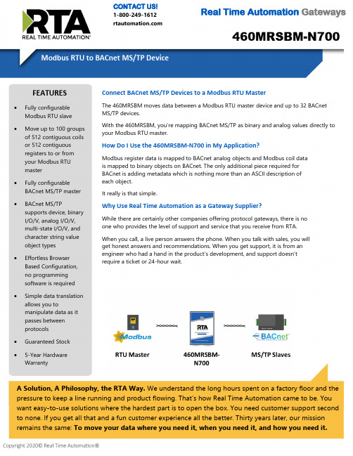
460MRSBM-N700CONTACT US!1-800-249-1612 Real Time Automation GatewaysA Solution, A Philosophy, the RTA Way. We understand the long hours spent on a factory floor and thepressure to keep a line running and product flowing. That’s how Real Time Automation came to be. Youwant easy-to-use solutions where the hardest part is to open the box. You need customer support secondto none. If you get all that and a fun customer experience all the better. Thirty years later, our mission remains the same: To move your data where you need it, when you need it, and how you need it.Connect BACnet MS/TP Devices to a Modbus RTU MasterThe 460MRSBM moves data between a Modbus RTU master device and up to 32 BACnet MS/TP devices.With the 460MRSBM, you’re mapping BACnet MS/TP as binary and analog values directly to your Modbus RTU master.How Do I Use the 460MRSBM-N700 in My Application?Modbus register data is mapped to BACnet analog objects and Modbus coil data is mapped to binary objects on BACnet. The only additional piece required for BACnet is adding metadata which is nothing more than an ASCII description of each object.It really is that simple.Why Use Real Time Automation as a Gateway Supplier?While there are certainly other companies offering protocol gateways, there is no one who provides the level of support and service that you receive from RTA. When you call, a live person answers the phone. When you talk with sales, you will get honest answers and recommendations. When you get support, it is from an engineer who had a hand in the product’s development, and support doesn’t require a ticket or 24-hour wait.FEATURES •Fully configurable Modbus RTU slave •Move up to 100 groupsof 512 contiguous coils or 512 contiguousregisters to or fromyour Modbus RTU master•Fully configurableBACnet MS/TP master •BACnet MS/TPsupports device, binary I/O/V, analog I/O/V,multi-state I/O/V, and character string value object types •Effortless BrowserBased Configuration, no programmingsoftware is required •Simple data translationallows you tomanipulate data as itpasses between protocols • Guaranteed Stock •5-Year Hardware WarrantyReal Time Automation, Inc.************************** - 1-800-249-1612Made in theU.S.A.Always InStockReady toShipExpertSupportModbus RTU Slave Operation ModeModbus RTU Slave Function Codes Supported 1,2,3,4,5,6, 15 & 16SwappingByte and Word Swapping Maximum Modbus RTU Master Connections 1Contiguous Data Areas 200 Total - 100 reads & 100 writesData Area Limits512 Contiguous Coils or 512 Contiguous RegistersBACnet MS/TP Master Operation ModeBACnet MS/TP Master InitiatorSupported Object Types Device, BI/BO/BV, AI/AO/AV, MI/MO/MV, Character String ValueSupported Service CodesRead Property-A, Read Property Multiple-A, Write Property-A, Write Property Multiple-A, Device Dynamic Binding-A Maximum Connections32Number Read/Write Scan Lines per Device 200 Total - 100 reads & 100 writes Scan Line SupportUp to 128 Objects INCLUDED WITH GATEWAY 3’ power cable with flying leads5-year hardware warrantyIPSetup software – automatically locates RTA gateway on the networkUnlimited firmware feature upgrades for lifeCAT5 crossover cable for direct connection to PC during programming Complete, unlimited access to our industry leading support staff ManualELECTRICAL / ENVIRONMENTALDC Input Voltage 12-24 VDC .Maximum Baud Rate 115K baud Operating Temperature -40 C to 85 CCertificationRoHS-Compliant, UL, CUL, CE Approvals ENCLOSURE / HARDWARE Size 4.19" x 3.25" x 1" Weight6.5 ozEnclosure Type Anodized Aluminum Mounting Din rail or panel mountLEDsPower LED, Ethernet link/data LED, & Ethernet speed LEDGATEWAY FEATURES & FUNCTIONSAlarming Set <, <=, >, >=, ==, !=, and change-of-state ruleson any data moving through the gateway. If alarmrule is triggered an email notification can be sent. Gateway SecurityYou can configure up to 9 different users access todiagnostic and configuration screens. Translation TableAllows for data manipulation during protocol translation. Scaling and other data format changes can occur in the gateway.Status and CountersProtocol specific status, counters, and error messages are accessible within the gateway’s diagnostics page. They can also be delivered to a connected device.NOT EXACTLY WHAT YOU WERE LOOKING FOR? Real Time Automation offers a full line of gateway products. Give us a call at 1-800-249-1612. Or, check out a listing at/products . We also offercustomizations for unique applications.Diagnostic Logging PageAllows users to see and log start up sequences, protocol specific messages & error messages.CATALOG # DESCRIPTION460MRSBM-N700Connects a Modbus RTU master with as many as 32 BACnet MS/TP slaves。

Pixhawk多轴使用说明书(V1.4.2)乐迪Pixhawk飞控四轴(ArduCopter)版本信息介绍V1版本:完善基本操作说明V1.1版本:添加失控保护介绍V1.3版本:添加日志,EKF失控保护的介绍V1.4版本:飞行模式和解锁故障保护的详细介绍V1.4.1版本:完善电流计设置V1.4.2版本:修改.net、MP的下载链接、修改罗盘的校准方法简介非常感谢您购买深圳市乐迪电子有限公司生产的pixhawk飞控。
Pixhawk自动驾驶仪(简称pix)是一款非常优秀而且完全开源的自动驾驶控制器,他的前世就是大名鼎鼎的APM,由于APM的处理器已经接近满负荷,没有办法满足更复杂的运算处理,所以硬件厂商采用了目前最新标准的32位ARM处理器,第一代产品是PX4系列,他分为飞控处理器PX4FMU和输入输出接口板PX4IO。
PX4系列可以单独使用PX4FMU(但是接线很复杂),也可以配合输入输出接口板PX4IO来使用,但是因为没有统一的外壳,不好固定,再加上使用复杂,所以基本上属于一代实验版本。
通过PX4系列的经验,厂商终于简化了结构,把PX4FMU和PX4IO整合到一块板子上,并加上了骨头形状的外壳,优化了硬件和走线,也就是这款第二代产品Pixhawk。
可应用于固定翼、直升机、多旋翼、地面车辆等,建议:在您阅读本说明书时,边阅读边操作。
您在阅读这些说明时,如遇到困难请查阅本说明书或致电我们售后(0755-********)及登陆航模类论坛(如:/forum.php?mod=forumdisplay&fid=277泡泡老师教程,,航模吧,乐迪微信公众平台,乐迪官方群:334960324)查看相关问题问答。
乐迪微信公众平台乐迪官方群售后服务条款1,本条款仅适用于深圳市乐迪电子有限公司所生产的产品,乐迪通过其授权经销商销售的产品亦适用本条款。
2,乐迪产品自购买之日起,一周内经我司核实为质量问题,由乐迪承担返修产品的往返快递费,购买乐迪产品超过一周到一年内经我司核实为质量问题,用户和乐迪各自承担寄出返修产品的快递费。

460ETCBC-NNA1CONTACT US!1-800-249-1612 Real Time Automation GatewaysA Solution, A Philosophy, the RTA Way. We understand the long hours spent on a factory floor and thepressure to keep a line running and product flowing. That’s how Real Time Automation came to be. Youwant easy-to-use solutions where the hardest part is to open the box. You need customer support secondto none. If you get all that and a fun customer experience all the better. Thirty years later, our mission remains the same: To move your data where you need it, when you need it, and how you need it.Connect BACnet/IP Servers to Allen-Bradley PLCsThe 460ETCBC moves data between a network of up to 32 BACnet/IP server devices and up tofive Allen-Bradley PLCs.With the 460ETCBC, you are making a direct connection between BACnet data and user-defined tags or registers in the data table of your Allen-Bradley PLC. There is no polling from the PLC or EtherNet/IP scan lists to arrange.How Do I Use the 460ETCBC-NNA1 in My Application?You allocate two areas of tags or register blocks in your Allen-Bradley PLC. One area is write only tags or register blocks accepting data from BACnet. The other is read only tags or register blocks to send data to your BACnet devices. It’s really that simple.Why Use Real Time Automation as a Gateway Supplier?While there are certainly other companies offering protocol gateways, there is no one who provides the level of support and service that you receive from RTA. When you call, a live person answers the phone. When you talk with sales, you will get honest answers and recommendations. When you get support, it is from an engineer who had a hand in the product’s development, and support doesn’t require a ticket or 24-hour wait.FEATURES •Supports connection to five Allen-Bradley PLCs •Up to 150 tag or filearrays of data can be mapped in eachdirection •Fully configurable BACnet/IP client •BACnet/IP supports device, binary I/O/V,analog I/O/V, multi-state I/O/V, and character string valueobject types•Effortless Browser Based Configuration, no programmingsoftware is required• Simple data translationallows you to manipulate data as itpasses between protocols• Guaranteed Stock •5-Year Hardware WarrantyReal Time Automation, Inc.************************** - 1-800-249-1612Made in theU.S.A.Always InStockReady toShipExpertSupportEthernet Tag Client PLC SupportControlLogix, CompactLogix, FlexLogix, MicroLogix, SLCs and PLC5Es Maximum Number of PLCs Supported5 Maximum Number of Input/Output Tags or Files per PLC150Maximum Number of Bytes per PLC Tag 400Array SupportYes, for all data types except stringsSupported Data Types Usint, Sint, Uint, Int, Udint, Dint, Real, String, Bit Array 16, Bit Array 32, Bool, and Long BACnet/IP Client Operation ModeBACnet/IP ClientSupported Object Types Device, BI/BO/BV, AI/AO/AV, MI/MO/MV, Character String ValueSupported Service CodesRead Property-A, Read Property Multiple-A, Write Property-A, Write Property Multiple-A, Device Dynamic Binding-A Maximum Connections32Number Read/Write Scan Lines per Device 200 Total - 100 reads & 100 writes Scan Line SupportUp to 128 Objects INCLUDED WITH GATEWAY 3’ power cable with flying leads5-year hardware warrantyIPSetup software – automatically locates RTA gateway on the networkUnlimited firmware feature upgrades for lifeCAT5 crossover cable for direct connection to PC during programming Complete, unlimited access to our industry leading support staff ManualELECTRICAL / ENVIRONMENTALDC Input Voltage 12-24 VDC .Maximum Baud Rate 115K baud Operating Temperature -40 C to 85 C Certification RoHS-Compliant, UL, CUL, CE Approvals ENCLOSURE / HARDWARE Size 3.88" x 2.57" x 1.06" Weight 5.5 oz Enclosure Type Anodized Aluminum Mounting Din rail or panel mount LEDs Power LED & 2 general purpose LEDs on side GATEWAY FEATURES & FUNCTIONSAlarming Set <, <=, >, >=, ==, !=, and change-of-state ruleson any data moving through the gateway. If alarmrule is triggered an email notification can be sent. Gateway SecurityYou can configure up to 9 different users access todiagnostic and configuration screens. Translation TableAllows for data manipulation during protocol translation. Scaling and other data format changes can occur in the gateway.Status and CountersProtocol specific status, counters, and error messages are accessible within the gateway’s diagnostics page. They can also be delivered to a connected device.NOT EXACTLY WHAT YOU WERE LOOKING FOR? Real Time Automation offers a full line of gateway products. Give us a call at 1-800-249-1612. Or, check out a listing at/products . We also offercustomizations for unique applications.Diagnostic Logging PageAllows users to see and log start up sequences, protocol specific messages & error messages.CATALOG # DESCRIPTION460ETCBC-NNA1Connects up to five Allen-Bradley PLCs with as many as 32 BACnet/IP servers。
M电调校准说明电调是驱动电机用的调速器。
电调的作用:电机的电流很大,通常每个电机正常工作时的平均电流在3A左右,如果没有电调的存在,飞控板的I/O口无法承受这样大的电流。
电子调速器负责使电机运行在飞控(即APM或PX4)所请求的旋转速度。
多数电调需要校准,这样它们才能知道飞控发出的最小与最大的PWM值。
方法一:四个电调一起校准(1)打开你的发射机,并将油门摇杆置于最大。
(2)连接电池。
飞控上的红、蓝、黄LED灯会以循环模式亮起。
这说明APM已准备好在下一次你再连接时进入电调校准模式。
(3)油门依然保持高,断开然后重新连接电池。
APM现在进入了电调校准模式,并让你的油门通过它直达电调(你可能会注意到红色和蓝色的LED的灯交替闪烁,就像警车一样)。
PX4用户另外需要按下安全按钮。
(4)等待你的电调发出音乐声,“哔”音数量通常表明你的电池芯数(即2S为2声,3S为3声),接下来另外两个“哔”音表示最大油门已被捕获。
(5)马上将油门拉到最小,电调会发出长音,表示成功捕获油门的最小值。
(6)把油门放低然后断开并重新连接电池。
此时,再将油门轻轻加上去,电机开始转起来,四个电调校准完毕。
方法二:四个电调单个校准逐个对四个电调进行校准,其方法与四个电调一起校准大同小异,只是看哪个方便而已。
(1)将电调的信号线与接收机的第三通道(即油门通道)连接,此时第三通道可以直接给电调信号。
(2)油门打到最大,给电调上电(连上电池),你会听到一段音乐声而后有两个“哔”音。
成功捕获最大值。
(3)在两个“哔”音之后,再将油门摇杆打到最低,然后你会听到几声“哔”音(每一声代表你所使用的电池的一节),随后一个长“哔”声表示终点已被设定而且电调已校准。
(4)拔下电池。
一个电调油门行程校准完毕,另外三个重复以上步骤即可。
如果出现电调不能校准,说明发射机上的油门通道可能需要反向。
如果你在尝试了这些方法之后仍遇到问题(举个例子,电调仍旧响个不停),尝试调低你的油门微调50%,另外可以尝试在插上锂电池之前先通过USB给你的APM板供电启动它。
460ETCSC-N2ECONTACT US!1-800-249-1612 Real Time Automation GatewaysA Solution, A Philosophy, the RTA Way. We understand the long hours spent on a factory floor and thepressure to keep a line running and product flowing. That’s how Real Time Automation came to be. Youwant easy-to-use solutions where the hardest part is to open the box. You need customer support secondto none. If you get all that and a fun customer experience all the better. Thirty years later, our mission remains the same: To move your data where you need it, when you need it, and how you need it.Connect Allen-Bradley PLCs to Your S7 PLCsThe 460ETCSC moves data between Allen-Bradley PLCs and up to five Siemens S7 PLCs.Featuring separate Ethernet network connections for each network.With the 460ETCSC, you are making a direct connection between S7 PLC data and user-defined tags or registers in the data table of your Allen-Bradley PLC. There is no polling from the PLC or EtherNet/IP scan lists to arrange.How Do I Use the 460ETCSC-N2E in My Application?You allocate two blocks of tag/register in your Allen-Bradley PLC. One area for reads and one for writes. Those locations are mapped to corresponding memory block addresses in your S7 PLC.It’s really that simple. Need to modify your data as it passes from one protocol to the other? No problem. Each data mapping you apply can be modified with up to three mathematic functions.Why Use Real Time Automation as a Gateway Supplier?While there are certainly other companies offering protocol gateways, there is no one who provides the level of support and service that you receive from RTA. When you call, a live person answers the phone. When you talk with sales, you will get honest answers and recommendations. When you get support, it is from an engineer who had a hand in the product’s development, and support doesn’t require a ticket or 24-hour wait.FEATURES •Supports connection to five Allen-Bradley PLCs •Up to 150 tag or filearrays of data can be mapped in eachdirection•Supports connections to five Siemens S7 PLCs •Up to 150 read and 150 write requests perconnection•Effortless Browser Based Configuration, no programmingsoftware is required•Simple data translation allows you to manipulate data as itpasses between protocols• Guaranteed Stock •5-Year HardwareWarrantyReal Time Automation, Inc.************************** - 1-800-249-1612Made in theU.S.A.Always InStockReady toShipExpertSupportEthernet Tag Client PLC SupportControlLogix, CompactLogix, FlexLogix, MicroLogix, SLCs and PLC5Es Maximum Number of PLCs Supported5 Maximum Number of Input/Output Tags or Files per PLC150Maximum Number of Bytes per PLC Tag 400Array SupportYes, for all data types except stringsSupported Data Types Usint, Sint, Uint, Int, Udint, Dint, Real, String, Bit Array 16, Bit Array 32, Bool, and Long S7 Client PLC SupportS7 300/400/1200/1500 Maximum Number of PLCs Supported5 Maximum Number of Inputs/Outputs per PLC 150 Maximum Number of Bytes per Scan Line 400Memory Area Access Input (I), Output (Q), and Data Block( DB)Supported Data Types8 Bit Int, 16 Bit Int, 32 Bit Int, 32 Bit Float, Bool and Char Array INCLUDED WITH GATEWAY 3’ power cable with flying leads5-year hardware warrantyIPSetup software – automatically locates RTA gateway on the networkUnlimited firmware feature upgrades for lifeCAT5 crossover cable for direct connection to PC during programming Complete, unlimited access to our industry leading support staff ManualELECTRICAL / ENVIRONMENTALDC Input Voltage 12-24 VDC .Maximum Baud Rate 115K baud Operating Temperature -40 C to 85 CCertificationRoHS-Compliant, UL, CUL, CE Approvals, Class I Div 2ENCLOSURE / HARDWARE Size 5.40" x 3.83" x 1.19" Weight 7.6 oz Enclosure Type Anodized Aluminum Mounting Din rail or panel mount LEDs Power LED & 2 general purpose LEDs on side GATEWAY FEATURES & FUNCTIONSAlarming Set <, <=, >, >=, ==, !=, and change-of-state ruleson any data moving through the gateway. If alarmrule is triggered an email notification can be sent. Gateway SecurityYou can configure up to 9 different users access todiagnostic and configuration screens. Translation TableAllows for data manipulation during protocol translation. Scaling and other data format changes can occur in the gateway.Status and CountersProtocol specific status, counters, and error messages are accessible within the gateway’s diagnostics page. They can also be delivered to a connected device.NOT EXACTLY WHAT YOU WERE LOOKING FOR? Real Time Automation offers a full line of gateway products. Give us a call at 1-800-249-1612. Or, check out a listing at/products . We also offercustomizations for unique applications.Diagnostic Logging PageAllows users to see and log start up sequences, protocol specific messages & error messages.CATALOG # DESCRIPTION460ETCSC-N2EConnects up to five Allen-Bradley PLCs with up to five S7 PLCs。
SX460发电机自动电压调节器使用手册版本 1.0日期:2015/07/02SX460版本历史记录:日期版本内容2015-07-02 1.0首次发行目录1.技术参数 (3)2.接线 (3)3.使用时注意事项 (4)4.调节 (4)5.磁场初期电压诱起 (5)6.故障排除表 (8)1.技术参数项目参数内容检测与电源输入电压95一132VAC或190一264VAC 单相以跨接铜片设定频率50/60Hz以跨接铜片设定输出电压207VAC输入时最大90VDC 电流连续4A,非连续为10秒内6A 电阻最小15Ohm外部电压调节用1K Ohms1Watt电位器时为±7%电压缓慢建立时间2秒电压调节率<±1.5%(发动机转速变动在4%内)电压建立在AV R输入端子需剩磁电压5VAC以上温差稳定度每℃变化,电压漂移0.05%消耗功率最大10Watt低频保护拐点值:95%Hz斜率:下降至30Hz时为170%尺寸135mm L*100mm W重量0.45KG±2%2.接线(如图四、五)2.1.将发电机之磁场引线连接于F+、F-接口2.2.连接检测电源线于7、8(出厂设定220V,若需设定110V时,请将3.4跨接短路).2.3.外部电压调节器如图四(视需求).2.4.选择50Hz或60Hz.2.5.选择R.S.T三相电压.注:建议使用一较高遮断容量之保险加装于电源(如图四),熔丝容量须依实际满载励磁场电流的120%.3.使用时注意事项3.1.安装时注意事项:(配置参考图一).3.1.1.安装、连接、调节、检查的作业由有专业知识人员实施.3.1.2.将调节器安装于发电机内防潮、防蚀且防止他人易碰触的地方.3.2.发电机运转时注意事项:3.2.1.在一般运转状况下,调节器表面温度会超过60℃.3.2.2.运转时,请勿碰触调节器散热板,也不可将调节器散热板接地或触碰外壳,已张贴警告标志.3.3.开机程序:3.3.1.初步设定:(1)确定一切接线正确.(2)将电压调节至最小.(3)假如使用外部电压电位器,则调节至中点.(4)调节稳定旋钮调节至最大.(5)用11OVDC电压表或三用表接F+、F-(F+接正、F-接负).(6)用300VAC表接交流输出端,检测交流输出电压.3.3.2.系统开动:(1)在空载状态下启动发电机,调节正确之转速,电压应建立于最低电压水平,假如不能建立电压时,(参阅5.以电瓶初期励磁或洽发电机商)。
rx4640HP Integrity rx4640动能服务器产品说明Integrity rx4640动能服务器具有128GB 的内存容量,最适合于企业资源规划、供应链管理以及业务智能应用。
与以往同等价位的系统相比,技术计算用户能够运行更多的模拟、执行更深入的分析。
借助集成的可扩展处理器芯片组zx1,Integrity rx4640动能服务器提高了内存和I/O 子系统的扩充能力,可以提升双核英特尔?安腾?2处理器的性能。
HP Integrity rx4640动能服务器提高了入门级服务器的性能,为商业应用提供了较高的性价比。
Integrity rx4640动能服务器可扩展至8个处理器内核,使业务部门的用户能够以较低价位运行要求苛刻的应用。
2HP Integrity 动能服务器:凭借灵活的容量、安全的可用性和简化的管理,为您提供更佳的IT 投资回报。
主要特性及优势提高的部署和重新部署灵活性—您能够在带有惠普(HP )虚拟服务器环境的HP -UX 11 i v2、Microsoft ? Windows ? Server 2003、Red Hat Enter-prise Linux 、Novell SUSE Linux Enterprise Server 以及Open VMS 中,灵活部署适合业务的应用,并从中受益。
HP Integrity rx4640动能服务器包含了您在运行HP-UX 、Linux 、Windows 或Open VMS 环境时通常所期望的全部管理、可用性和安全特性。
这种灵活性支持针对异构IT 环境中的部署和重新部署进行无缝的集成和管理,显著提高了计算资源的利用率。
高容量和可扩展性—新一代双核英特尔?安腾?2处理器以高达1.6GHz 的时钟频率运行,可支持高达24MB 的3级高速缓存。
此外,作为英特尔的联合开发者,惠普(HP )借助自身掌握的英特尔?安腾?处理器方面的专业知识,开发出了HP zx1芯片组,它有助于大幅提升系统性能。
PX460
编号载体名称
北京华越洋VECT75250
PX460
PX460载体基本信息:
载体名称:PX460或pSpCas9n(BB)
质粒类型:CRISPR-Cas9载体;基因敲除载体;哺乳动物载体
高拷贝/低拷贝:高拷贝
插入位点:限制性内切酶,多克隆位点
启动子:
Cbh
载体大小:
8506bp
5'测序引物及序列:
TTTATGGCGAGGCGGCGG
3'测序引物及序列:BGHReverse:TAGAAGGCACAGTCGAGG
载体标签:3XFLAG、SV40NLS、NLS(Nter)
载体抗性:氨苄青霉素
筛选标记:
--
克隆菌株:
Stbl3
宿主细胞(系):常规哺乳动物细胞
备注:
Cas9D10Anickasemutant
稳定性:瞬表达
组成型/诱导型:组成型
病毒/非病毒:非病毒
PX460载体质粒图谱和多克隆位点信息:
PX460载体其他相关CRISPR/Cas9载体:
pCaspgRNA-humanizedPX330S-2
pX330A-1x2pWJ66pWJ68
pwtCas9-bacteriapgRNA-bacteriapET-Cas9-NLS-6xHis
pET-Cas9-6xHispET-28b-Cas9-HispCas-Guide-Nickase
pCas-Guide-EF1a-CD4pCas-Guide-AAVS1pCas-Guide
pCas9D10A-GFPpX603PX544
PX399PX398PX396
PX393PX392PX391
PX389eSpCas9(1.1)PX388
PX386PX385PX381
PX383PX380PX379
PX377PX333PX165
PX551PX460PX429
PX260PX334pCas9
PX856PX855PX854
PX852lentidCAS-VP64_BlastlentiCRISPRv2
PX461pX851pX600
pX602PX459PX458
pGuide-IT-ZsGreen1PX395PX335
pFGC-pcoCas9PX390pdCas9-humanized
PX330PX387PX853
pET-NLS-Cas9-6xHisPX382PX462
pCas-Guide-EF1a-GFPPX378pX601
pCas9-GFPPX552pGuide-IT-tdTomato
PX543