氦压缩机说明书+F-70H+and+F-70L+H...
- 格式:pdf
- 大小:908.55 KB
- 文档页数:52
氦气安全技术说明书产品名称:氦,压缩气体Helium,compressde化学名称:氦分子式:He代名称:氦气,气态氦企业名称:产品信息(查询电话):氦纯度≥99.999%暴露极限:AGIH:简单窒息剂NIOSH:未建立OSHA:未建立氦气存储在高压气瓶内,是一种无毒、无色、无嗅,不可燃的气体。
当空气中氦含量过高而使氧含量低于<19.5%时,会导致快速窒息,它比空气轻,可能会聚集在高处及天花板周围。
这时需给救援人员配备自给式呼吸器(SCBA)。
急性潜在健康影响:吸入:简单的窒息剂。
氦是无毒气体,但它会置换出空气中的氧而引起窒息。
缺氧会引起严重的伤害或死亡。
眼接触:无不良影响皮肤接触:无不良影响暴露资料:无侵入途径:吸入损害器官:无影响结果:窒息症状:若人员处于含氧量在19.5%以下的空气中,会引起眩晕、疲倦、恶心、呕吐、唾液过多,反应迟钝,失去知觉甚至死亡。
若人员处于含有8-10%或更少的含氧量的空气中,将会很快无任何先兆地失去知觉,失去自我救护及的能力。
过分暴露造成的病状恶化:无致癌性:未被NTP、OSHA及IARC列为致癌或潜在致癌物。
警告任何故意吸入氦气以图改变发音效果的尝试都是极端危险的,并可能造成严重的伤害甚至死亡。
吸入:将由于缺氧窒息人员移到空气清新处。
若受难者已停止呼吸,立即采用人工呼吸。
若呼吸困难,则输氧,并迅速进行医务处理。
眼接触:不适用皮肤接触:不适用闪点:自然点:燃烧极限:不适用不可燃不可燃灭火剂:氦不可燃且不燃。
使用适合其周围燃烧物质的灭火材料。
有害燃烧产物:无特殊灭火指导:氦是一种简单的窒息剂,如果可能,在没有危险的情况下从火场移走钢瓶或用水冷却。
营救人员需用自给式呼吸器。
异常火灾和爆炸危害:当气瓶处于高温或有火的环境中会迅速排放或激烈爆炸。
大部分气瓶设计了温度升高时的泄压装置.由于热量的作用气瓶内压力会上升,如果泄压装置失灵会引起钢瓶爆炸。
将所有人员撤离泄漏区域,使该区域加强通风,检测氧气含量。

Table 1Compression Factors and “A” Constants“A” Constants for VariousInlet CompressionPressure Drop *Pressure Factor2 PSI 5 PSI 10 PSI (PSIG)P P P 10 1.6.155.10220 2.3.129.083.06630 3.0.113.072.05540 3.7.097.064.04850 4.4.091.059.04360 5.1.084.054.04070 5.7.079.050.03780 6.4.075.048.035907.1.071.045.0331007.8.068.043.0311108.5.065.041.0301209.2.062.039.0291309.9.060.038.02814010.6.058.037.02715011.2.056.036.02616011.9.055.035.02617012.6.054.034.02518013.3.052.033.02419014.0.051.032.02420014.7.050.031.023Note: Use “A” constant at 5 PSI P. P for most applications. On very criticalapplications, use “A” at 2 PSI P. You will find in many cases, a 10 PSI P is not detrimental, and can save money and mounting space.*where T is for68°F and G =1 for Air.DefinitionsCE ...........Certification of a product to meet EuropeanCommunity standards. “H” ISO solenoid valves are approved for CE.CSA NRTL-C ...Canadian Standards Association andapplicable for UL. (See Pages 30 & 45)IP65.........International classification system for sealingeffectiveness for enclosures of electricalequipment. IP stands for “Ingress Protection” and the two digits XY stand for: X - protection from solid objects and Y - protection from moisture. IP 65 is protection from dust and water washdown.NEMA 4...National standard for enclosure protection.NEMA 4 provides protection against dirt, dust,water hosedown and rain. (Similar to IP 65)NLMOR ...Non-Locking Manual Override. A constantactuation must be maintained for the valve to shift.LMOR ......Locking Manual Override. Valve stays shiftedwithout constant end user override actuation.Bi-Polar ..Solenoids are non-polarity sensitive and canbe reverse wired. All “H” ISO solenoids are non-polarity sensitive.SCFM ......Measure of air flow. Standard Cubic Feet perMinute at 68°F and 36% humidity at sea level.SurgeSuppression ..Nullifies reverse EMF generated when asolenoid is de-energized. “H” Series Voltage Code 12, 15, 19, 23, 83, 87 and B9 include surge suppression.PSIG ........Pounds per Square Inch measured with a gage.(Catalog pressure reflects PSIG)PSIA ........Pounds per Square Inch atmospheric.kPa ..........Kilopascals. International measure of pressure.1035 kPa = 150 PSIGPSIG = 0 PSIA = 14.7 In. of Hg = 29.92 kPa = 0C v CalculationsC v ............Measure of calculating flow of a valve (or otherpneumatic device) that takes into effect thetemperature, pressure, pressure drop, and flow.As a rule of thumb, a Cv of 1.0 is 25 SCFM with a 5 PSIG pressure drop.Cylinder Area Cylinder Compression “A”(Sq. In.)XStroke X Factor X(T able 1)C v =(See Table 2)(In.)(Table 1)Stroke Time (sec.) x 28.8Table 2Effective Square-Inch Areas for Standard-Bore-Size CylindersBore Cylinder Area Bore Cylinder Area Size(Sq. In.)Size(Sq. In.)3/4".444"12.571".7941/2"15.9011/8".995"19.6411/4" 1.236"28.2711/2" 1.777"38.4813/4" 2.418"50.272" 3.1410"78.5421/2" 4.9112"113.1031/4"8.3014"153.9435/8"10.32Product Shipping Weights“H” ISO Series Valves 5599-2 / 5599-1Catalog 0632-6/USADefinitions, WeightThe items described in this document and other documents or descriptions provided by Parker Hannifin Corporation, its subsidiaries and its authorized distributors, are hereby offered for sale at prices to be established by Parker Hannifin Corporation, its subsidiaries and its authorized distributors. This offer and its acceptance by any customer (“Buyer”) shall be governed by all of the following Terms and Conditions. Buyer’s order for any such item, when communicated to Parker Hannifin Corporation, its subsidiaries or an authorized distributor (“Seller”) verbally or in writing, shall constitute acceptance of this offer.1. Terms and Conditions of Sale: All descriptions, quotations, proposals, offers, acknowledgments, acceptances and sales of Seller’s products are subject to and shall be governed exclusively by the terms and conditions stated herein. Buyer’s acceptance of any offer to sell is limited to these terms and conditions. Any terms or conditions in addition to, or inconsistent with those stated herein, proposed by Buyer in any acceptance of an offer by Seller, are hereby objected to. No such additional, different or inconsistent terms and conditions shall become part of the contract between Buyer and Seller unless expressly accepted in writing by Seller. Seller’s acceptance of any offer to purchase by Buyer is expressly conditional upon Buyer’s assent to all the terms and conditions stated herein, including any terms in addition to, or inconsistent with those contained in Buyer’s offer. Acceptance of Seller’s products shall in all events constitute such assent.2. Payment: Payment shall be made by Buyer net 30 days from the date of delivery of the items purchased hereunder. Amounts not timely paid shall bear interest at the maximum rate permitted by law for each month or portion thereof that the Buyer is late in making payment. Any claims by Buyer for omissions or shortages in a shipment shall be waived unless Seller receives notice thereof within 30 days after Buyer’s receipt of the shipment.3. Delivery: Unless otherwise provided on the face hereof, delivery shall be made F.O.B. Seller’s plant. Regardless of the method of delivery, however, risk of loss shall pass to Buyer upon Seller’s delivery to a carrier. Any delivery dates shown are approximate only and Seller shall have no liability for any delays in delivery.4. Warranty: Seller warrants that the items sold hereunder shall be free from defects in material or workmanship for a period of 18 months from date of shipment from Parker Hannifin Corporation. THIS WARRANTY COMPRISES THE SOLE AND ENTIRE WARRANTY PERTAINING TO ITEMS PROVIDED HEREUNDER. SEL L ER MAKES NO OTHER WARRANTY, GUARANTEE, OR REPRESENTATION OF ANY KIND WHATSOEVER. ALL OTHER WARRANTIES, INCLUDING BUT NOT LIMITED TO, MERCHANTABILITY AND FITNESS FOR PURPOSE, WHETHER EXPRESS, IMPLIED, OR ARISING BY OPERATION OF L AW, TRADE USAGE, OR COURSE OF DEAL ING ARE HEREBY DISCLAIMED.NOTWITHSTANDING THE FOREGOING, THERE ARE NO WARRANTIES WHATSOEVER ON ITEMS BUIL T OR ACQUIRED WHO L L Y OR PARTIA L L Y, TO BUYER’S DESIGN OR SPECIFICATIONS.5. Limitation of Remedy: SELLER’S LIABILITY ARISING FROM OR IN ANY WAY CONNECTED WITH THE ITEMS SOL D OR THIS CONTRACT SHAL L BE L IMITED EXCL USIVEL Y TO REPAIR OR REPL ACEMENT OF THE ITEMS SOL D OR REFUND OF THE PURCHASE PRICE PAID BY BUYER, AT SELLER’S SOLE OPTION. IN NO EVENT SHALL SELLER BE LIABLE FOR ANY INCIDENTAL, CONSEQUENTIAL OR SPECIAL DAMAGES OF ANY KIND OR NATURE WHATSOEVER, INCLUDING BUT NOT LIMITED TO LOST PROFITS ARISING FROM OR IN ANY WAY CONNECTED WITH THIS AGREEMENT OR ITEMS SOLD HEREUNDER, WHETHER ALLEGED TO ARISE FROM BREACH OF CONTRACT, EXPRESS OR IMPLIED WARRANTY, OR IN TORT, INCL UDING WITHOUT L IMITATION, NEGLIGENCE, FAILURE TO WARN OR STRICT LIABILITY.6. Changes, Reschedules and Cancellations: Buyer may request to modify the designs or specifications for the items sold hereunder as well as the quantities and delivery dates thereof, or may request to cancel all or part of this order, however, no such requested modification or cancellation shall become part of the contract between Buyer and Seller unless accepted by Seller in a written amendment to this Agreement. Acceptance of any such requested modification or cancellation shall be at Seller’s discretion, and shall be upon such terms and conditions as Seller may require.7. Special Tooling: A tooling charge may be imposed for any special tooling, including without limitations, dies, fixtures, molds and patterns, acquired to manufacture items sold pursuant to this contract. Such special tooling shall be and remain Seller’s property notwithstanding payment of any charges by Buyer. In no event will Buyer acquire any interest in apparatus belonging to Seller which is utilized in the manufacture of the items sold hereunder, even if such apparatus has been specially converted or adapted for such manufacture and notwithstanding any charges paid by Buyer. Unless otherwise agreed, Seller shall have the right to alter, discard or otherwise dispose of any special tooling or other property in its sole discretion at any time.8. Buyer’s Property: Any designs, tools, patterns, materials, drawings, confidential information or equipment furnished by Buyer, or any other items which become Buyer’s property, may be considered obsolete and may be destroyed by Seller after two (2) consecutive years have elapsed without Buyer placing an order for the items which are manufactured using such property. Seller shall not be responsible for any loss or damage to such property while it is in Seller’s possession or control.9. Taxes: Unless otherwise indicated on the face hereof, all prices and charges are exclusive of excise, sales, use, property, occupational or like taxes which may be imposed by any taxing authority upon the manufacture, sale or delivery of the items sold hereunder. If any such taxes must be paid by Seller or if Seller is liable for the collection of such tax, the amount thereof shall be in addition to the amounts for the items sold. Buyer agrees to pay all such taxes or to reimburse Seller therefore upon receipt of its invoice. If Buyer claims exemption from any sales, use or other tax imposed by any taxing authority, Buyer shall save Seller harmless from and against any such tax, together with any interest or penalties thereon which may be assessed if the items are held to be taxable.10. Indemnity For Infringement of Intellectual Property Rights: Seller shall have no liability for infringement of any patents, trademarks, copyrights, trade dress, trade secrets or similar rights except as provided in this Part 10. Seller will defend and indemnify Buyer against allegations of infringement of U.S. patents, U.S. trademarks, copyrights, trade dress and trade secrets (hereinafter “Intellectual Property Rights”). Seller will defend at its expense and will pay the cost of any settlement or damages awarded in an action brought against Buyer based on an allegation that an item sold pursuant to this contract infringes the Intellectual Property Rights of a third party. Seller’s obligation to defend and indemnify Buyer is contingent on Buyer notifying Seller within ten (10) days after Buyer becomes aware of such allegations of infringement, and Seller having sole control over the defense of any allegations or actions including all negotiations for settlement or compromise. If an item sold hereunder is subject to a claim that it infringes the Intellectual Property Rights of a third party, Seller may, at its sole expense and option, procure for Buyer the right to continue using said item, replace or modify said item so as to make it noninfringing, or offer to accept return of said item and return the purchase price less a reasonable allowance for depreciation. Notwithstanding the foregoing, Seller shall have no liability for claims of infringement based on information provided by Buyer, or directed to items delivered hereunder for which the designs are specified in whole or part by Buyer, or infringements resulting from the modification, combination or use in a system of any item sold hereunder. The foregoing provisions of this Part 10 shall constitute Seller’s sole and exclusive liability and Buyer’s sole and exclusive remedy for infringement of Intellectual Property Rights.If a claim is based on information provided by Buyer or if the design for an item delivered hereunder is specified in whole or in part by Buyer, Buyer shall defend and indemnify Seller for all costs, expenses or judgements resulting from any claim that such item infringes any patent, trademark, copyright, trade dress, trade secret or any similar right.11. Force Majeure: Seller does not assume the risk of and shall not be liable for delay or failure to perform any of Seller’s obligations by reason of circumstances beyond the reasonable control of Seller (hereinafter “Events of Force Majeure”). Events of Force Majeure shall include without limitation, accidents, acts of God, strikes or labor disputes, acts, laws, rules or regulations of any government or government agency, fires, floods, delays or failures in delivery of carriers or suppliers, shortages of materials and any other cause beyond Seller’s control.12. Entire Agreement/Governing Law: The terms and conditions set forth herein, together with any amendments, modifications and any different terms or conditions expressly accepted by Seller in writing, shall constitute the entire Agreement concerning the items sold, and there are no oral or other representations or agreements which pertain thereto. This Agreement shall be governed in all respects by the law of the State of Ohio. No actions arising out of sale of the items sold hereunder or this Agreement may be brought by either party more than two (2) years after the cause of action accrues.Catalog 0632-6/USA Offer of SaleParker Hannifin Corporation Pneumatic Division8676 E. M89P.O. Box 901Richland, MI 49083 USA Tel:(269) 629-5000Fax:(269) 629-5385Customer/T echnical ServiceTel:(269) 629-5575Fax:(800) 648-5480Fax:(800) 426-3259Web site:/pneumatic。
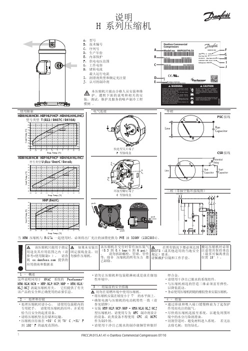
FRCC.PI.015.A1.41 © Danfoss Commercial Compressors 07/101说明H 系列压缩机E v ap. T em p. (°C )C o n d . T e m p . (°C )E v ap. T em p. (°C )C o n d . T e m p . (°C )E v ap. T em p. (°C )C o n d . T em p . (°C )A: 型号B: 技术编号C: 序列号D: 生产年份E: 内部保护F: 供电电压范围G: 工作电容H: 堵转电流 最大运行电流I: 润滑剂类型和额定充注量J: 认可的制冷剂HRM/HLM/HCM - HRP/HLP/HCP - HRH/HLH/HLJ/HCJHRM/HLM/HCM - HRP/HLP/HCP - HRH/HLH/HLJ/HCJ型号类型 U (R22 / R407C / R410A)本压缩机只能由合格人员安装和维护。
遵照下面的说明和相关的安装,调试,维护及服务的噪声制冷工程惯例 。
Wiring diagram with pump-down cycleAD I J400PSC 接线CSR 接线使用限制电气连接单相三相(带抽空循环接线图)1 – 概述这些说明同用于 HVAC 系统的 Performer® Hrm/HLm/HCm - HrP/HLP/HCP/HHP - HrH/HLH/HLJ/HCJ 涡旋压缩机有关。
它们提供了有关该产品的安全和正确使用的必要信息。
2 – 处理和存储 •处理压缩机时请小心。
请使用包装箱内的专用把手。
请使用压缩机的吊环,并采用恰当且安全的起重设备。
• 请将压缩机竖直存储和运输。
•压缩机应存放在 -35°C 到 70°C /-31°F 到 158°F 的温度范围内。

氟利昂压缩机及压缩冷凝机组说明书安徽科海压缩机制造有限公司中国·安徽·蚌埠目录一、结构、特点、性能和用途 (3)1、特点和用途 (3)2、压缩机结构简介 (3)3、主要技术参数 (4)二、制冷系统概述 (6)1、制冷系统的工作过程 (5)2、制冷剂 (7)3、润滑油 (7)三、安装、使用 (7)1、机组的安装 (7)2、吸、排气截止阀的使用 (8)3、润滑油油压的调节 (8)4、机组的操作 (9)5、添加润滑油 (9)6、放空气 (10)7、吸潮 (10)8、注意事项 (11)9、常见故障分析与补救方法 (11)一、结构、特点、性能和用途1、特点和用途F系列氟利昂压缩机及压缩机组、压缩冷凝组、专供氟利昂制冷剂使用,可作各种小型制冷设备的主机配套。
在国民经济的工业、农业、交通运输、医疗卫生、科学研究等各个部门有极其广泛的作用。
如:化学工业的炼气、炼油、造纸、人造纤维、制药等生产过程的冷却:食品工业中鱼、肉、乳脂、干酪等的冷却冷藏:以及船舶、火车的冷藏运输。
在空调方面如:中心实验室、计量室、机密仪器车间的恒温恒湿,和医院、剧场、餐厅、工厂车间的空气调节。
压缩机和电动机:分油器、控制仪表等均装于同一底座上,组成压缩机组,倘装于冷凝器上,则组成压缩冷凝机组,冷凝器系卧形壳管式,传热性能良好,耗水量小。
压缩机结构紧凑、运转平稳、具有良好的润滑系统,并带有氨气保护装置。
对单级氟利昂R-12压缩机所采用的蒸发温度是-20℃至+10℃,冷凝温度不高于+50℃,R-22时蒸发温度-40~+5℃,冷凝温度不高于+40℃活塞上的压力差均不超过1Mpa。
2、压缩机结构简介F系列氟利昂压缩机有4F70、4F80、2F10、4F10。
它们都是单级、单作用、逆流式压缩机。
二缸成直立式,四缸成V型。
曲轴箱和气缸体用高级铸铁铸成,曲轴采用球墨铸铁制成,两拐互成180 °。
连杆材料为可锻铸铁,断面呈工字型。

sumitomo cryogenics f-70压缩机参数-回复Sumitomo Cryogenics F70 压缩机参数概述先容:Sumitomo Cryogenics F70 压缩机是一种高效能压缩机,适用于广泛的工业应用。
它采用先进的技术并具有一系列的参数,使其能够在各种环境下提供可靠的性能和卓越的效率。
一、制冷性能参数F70 压缩机具有出色的制冷能力,其性能参数可以通过以下指标来衡量:1. 制冷容量:Sumitomo Cryogenics F70 压缩机的制冷容量为XXX。
这意味着它能够在单位时间内从低温的环境中吸收一定量的热量,并将其传递到高温环境中。
这使得该压缩机非常适合于需要高效制冷的应用领域。
2. 制冷温度:F70 压缩机能够提供低至-XXX的制冷温度。
通过实现如此低的温度,该压缩机使得冷冻系统能够满足各种严苛应用的需求,例如高科技制造、实验室和医疗领域。
3. 制冷效率:Sumitomo Cryogenics F70 压缩机的能效比(COP)为XXX。
该参数表示每单位电能输入,该压缩机能够产生多少制冷能力。
高能效比意味着更低的能源消耗,从而节约成本和减少环境影响。
二、机械参数F70 压缩机还具有一系列关键的机械参数,这些参数决定了其使用寿命、可靠性和运行效果:1. 压缩机类型:Sumitomo Cryogenics F70 压缩机采用螺杆压缩机技术,这种技术具有高效、稳定和低振动的特点。
螺杆压缩机通过两个旋转螺杆的相互作用,将气体压缩到所需的压力水平。
2. 压缩比:F70 压缩机的最大压缩比为XXX。
这意味着它能够将气体压缩至该压力的水平,而不会过载或损坏。
3. 运行速度:Sumitomo Cryogenics F70 压缩机的运行速度为XXX。
这个参数决定了压缩机在单位时间内的工作量。
较高的运行速度意味着更快的制冷过程,并且在需要快速响应和高效运行的应用中非常重要。
4. 排气温度:F70 压缩机的最高排气温度为XXX。

Z-0.28/(20-76)-250型天然气压缩机使用说明书ZNG20(II)·SM目录一、用途和适用范围二、主要规格及技术参数三、压缩机的主要结构及工作原理四、压缩机的安装五、压缩机的装配及拆卸注意事项六、压缩机的操作与使用七、压缩机的油封和保管八、运行故障与排除方法九、主要配合件装配间隙十、保证十一、产品成套设备、随机工具、备品备件、文件清单十二、随机安装图样一、用途和适用范围Z-0.28/(20-76)-250型天然气压缩机(以下简称压缩机),是将气体压力为2-20MPa 的净化天然气(经母站压缩机压缩,净化的天然气)压缩到25MPa,供气量为300-1350Nm3/h(吸气压力为2.0~7.6MPa时),输入车载气瓶内作为燃料代替汽油使用的主要设备。
该压缩机对天然气气质的要求:不含游离水,硫化氢(HS)含量<15mg/Nm3,低热2值≥31.4Mj/N m3,含尘量≤5mg/N m3,总硫含量(以硫计)≤100mg/N m3。
二、主要规格及技术参数(一)、压缩机1、型号:Z-0.28/(20-76)-2502、型式:Z型两级混冷活塞式3、压缩介质:净化天然气4、进气压力:2.0~20MPa5、压缩机启动压力:2.0~17MPa6、进气温度:≤30℃7、排气压力:25MPa8、排气温度:≤160℃(冷却前);≤环境温差+15℃(冷却后)9、排气量:0.28M3/min10、供气量:300~1350Nm3/h11、含油量:≤5ppm12、噪声:≤75dB(A)(箱体外1m处)13、传动方式:直联14、轴功率:≤72KW15、电机功率:75KW,防爆等级:dIIBT416、配电规格:50HZ,380V17、启动与控制(PLC)该机为全自动,即自动启停,自动排污。
主机软启动注油器启动后,主机延时启动。
(二)、主电动机:1、型号:YB315M-82、额定功率:75KW3、转速:740r/min4、电压:380V5、防爆等级:dIIBT4(三)、注油器电机:1、额定功率:0.55KW2、电压:380V3、防爆等级:dIIBT4(四)、控制柜:Z-0.28/(20-76)-250单机PLC控制柜(五)、风机电机(两台)1、额定功率:2×2KW2、电压:380V3、防爆等级:dIIBT4(六)、水泵电机1、额定功率:0.75KW2、电压:380V3、防爆等级:dIIBT4(七)、加热器功率约4×1.5KW三、压缩机的主要结构及工作原理:(一)、压缩机的主要结构压缩机为Z型,两级压缩,气体风冷、气缸内循环水冷活塞式,气缸中心线为竖直方向。
en Installation instructions1234265626enSafe installationFollow these safety instructions when installing the appliance.¡Read this instruction manual carefully.¡The images shown in these instructions are for guidance only.¡The appliance can only be used safely if it is cor-rectly installed according to the safety instructions.The installer is responsible for ensuring that the appliance works perfectly at its installation loca-tion.WARNING ‒ Risk of explosion!Escaping gas may cause an explosion.▶All Installation, connection, regulating and conver-sion work to a different gas type must be carried out by an authorised professional while taking into account the respective applicable regulations and legal requirements as well as the regulations re-garding the local electricity and gas suppliers.Special attention must be paid to the provisions and guidelines that are applicable for the ventila-tion. For conversion work to a different gas type,we recommend that you call the after-sales ser-vice.¡Ensure that the kitchen is sufficiently ventilated, in particular when operating the gas cooking appli-ance.¡Do not connect the appliance to an exhaust gas system for combustion products.¡Never install the appliance in boats or in vehicles.¡The warranty applies only when using the appli-ance as intended.¡Before installing the appliance, check that the local conditions of the supplier are compatible with the appliance settings specified on the rating plate (type of gas and pressure, power, voltage).¡Secure the power cord to the cabinet to prevent it from touching hot parts of the oven or hob.¡Before any work is carried out on the appliance,switch off the power supply and the gas supply.¡Connect the appliance to the power supply using the earth.¡Do not make any changes to the inside of the ap-pliance. If required, contact our technical cus-tomer service.Before installing¡This appliance is a class 3 appliance in accord-ance with the EN 30-1-1 standard for gas appli-ances: Built-in appliance.¡This appliance can be combined with other hobs of the same brand by using the connection ac-cessory. See catalogue.¡The unit in which the appliance is installed must be stable and secured appropriately.¡The units in the vicinity of the appliance, the lamin-ated panels and the adhesive with which they are secured must be made of non-flammable, heat-resistant materials.¡Do not install this appliance above refrigerators,washing machines, dishwashers or similar.¡The appliance must only be installed on an oven with forced ventilation. Check the dimensions of the oven in the installation instructions for the oven.¡If you install an oven underneath the hob, the work surface thickness may differ from the dimensions given in these instructions. Take note of the in-formation in the oven installation instructions.¡If you install an exhaust air fan or an extractorhood, refer to the installation instructions for these.Always observe the minimum vertical distance to the hob.→ Fig. 1Preparing the units¡Make a cut-out in the worktop with the required di-mensions.¡In recesses of 500 mm, the appliance must be in-stalled on the front edge of the recess. → "Posi-tioning the appliance", Page 7→ Fig. 2¡Seal the cut surfaces of wooden work surfaces with a special glue seal to protect them from mois-ture.¡If there is no built-in oven underneath the hob, in-sert a non-flammable separator (e.g. metal or ply-wood) at a distance of 10 mm from the hob. This prevents access to the underside of the hob. The distance from the intermediate floor to the mains connection for the appliance must be at least 10mm.→ Fig. 3, → Fig. 47Positioning the applianceNote: Do not remove the adhesive seal fitted on the lower edge of the hob. The adhesive seal prevents the penetration of liquids.Do not use silicone to bond the appliance to the worktop.1.Position the hob with the upper side facing down on a flat, stable surface.2.Loosen the screws on the brackets so they can turn freely. You do not need to fully undo the screws on the brackets.→ Fig. 53.Turn the hob around and insert it into the recess.Insert the hob in the front of the recess.→ Fig. 64.Turn the brackets and tighten them fully.→ Fig. 7The position of the brackets depends on the work-top thickness.Removing the appliance1.Disconnect the appliance from the electricity andgas connections.2.Unscrew the brackets and proceed in reverse or-der.Connecting the gasObserve the country-specific guidelines.CAUTION ‒ Risk of explosion!A gas leakage may cause an explosion.▶If any connection is handled, check the seal.¡Arrange the gas connection so that the shut-off valve is accessible.¡Ensure that the information on the rating plate re-garding the gas type and gas pressure complies with the local connection conditions.¡Connect the appliance to a fixed gas pipe or a flexible metal pipe.¡The flexible metal pipe must not come into contact with the moving parts of the unit in which the ap-pliance is installed (e.g. a drawer) and must not be routed through any spaces which might be-come obstructed.¡Gas connection on the appliance: G 1/2.Spare parts for gas connectionYou can obtain the gas connection parts from the technical customer service.Pipe10008834Pipe for horizontal connection10003285Gas connection G 1/2▶Insert the seal between the gas connection of the appliance and the gas supply.→ Fig. 8LPG rubber hose connection1.Secure the sealing ring and the pipe that is sup-plied in the accessory bag to the appliance's gas inlet elbow.2.Insert the rubber hose into the end of the pipe and tighten the screw on the hose clamp.→ Fig. 9Electrical connection¡This appliance is type Y: The connection cable must only be replaced by technical customer ser-vice and not by the user. The cable type and the minimum cross section must be respected.¡The hobs are supplied with a power cord with or without a plug.¡Only connect appliances that are fitted with a plug to a correctly installed socket with protective earth conductor.¡If the plug is not accessible to the user, an all-pole isolating safety switch with a minimum contact opening of 3 mm must be provided.→ Fig. 10Converting the gas typeIf the country's regulations allow, this appliance can be adapted to other types of gas, if these are listed on the rating plate.You can find the right parts in the bag that is sup-plied with the appliance or you can obtain them from customer service. The table → Fig. 26 shows the right combination for the relevant burner and gas type.¡2 - Inner flameToolsContact technical customer service to purchase the relevant tools.Removal lever483196Removing the upper part of the appliance (glass plate with cut-out profiles)1.Remove the pan supports, burner caps, distribut-ors and rotary knobs.2.Undo the screws on the burners.→ Fig. 113.Move the removal lever under the metal cut-out profile into the area marked for the hob model and loosen the front clip fastener.→ Fig. 12Only use the lever under the cut-out profiles or the metal frame of the hob.4.Carefully lift the glass plate with the cut-out pro-files to release the rear clip fastener.Removing the circuit boardTip: The circuit board is secured to the holder by fastening pins at the sides and in the middle. Push the fastening pins carefully without damaging them.If one of the pins breaks, the entire holder must be replaced.ATTENTION!The circuit board can be damaged by improper handling.▶Handle the circuit board carefully.▶Use anti-static shields or hold the circuit board at the edges.▶Never touch the surfaces of the circuit board on which there are components or conducting tracks.1.Undo the fastening pins on one side.2.Release the fastening pins in the middle by press-ing on them from both sides with your fingers.3.Undo the fastening pins on the other side and re-move the circuit board.→ Fig. 13Adjusting the tapsRequirement: The upper part of the appliance and the circuit board are removed. → "Removing the up-per part of the appliance (glass plate with cut-out profiles)", Page 7 → "Removing the circuit board", Page 71.Remove the cylindrical parts and springs from thefittings spindle.2.When adjusting the bypass screws (M), refer tothe table → Fig. 26.‒A: Firmly tighten the bypass screws.‒B: The bypass screws must be flush with the fit-ting.→ Fig. 14Replacing the nozzles▶Replace the nozzles using the appropriate wrench and tighten them carefully to guarantee the seal.→ Fig. 15Ensure that the nozzle does not become detached during removal or fastening.Replacing the outer flame nozzle on the multi-crown burnerRequirement: The upper part of the appliance has been removed. → "Removing the upper part of the appliance (glass plate with cut-out profiles)", Page 7 1.To gain access to the main nozzle, loosen thefastening screw and pull the sleeve back.→ Fig. 162.Remove the nozzle by turning it anti-clockwiseand screw in the new outer flame nozzle .→ Fig. 173.Set the spacing of the adjustment sleeve for theair supply to dimension Z, as shown in the table → Fig. 26.→ Fig. 184.Tighten the fastening screw.→ Fig. 19Replacing the inner flame nozzle on the multi-crown burnerRequirement: The upper part of the appliance has been removed. → "Removing the upper part of the appliance (glass plate with cut-out profiles)", Page 7 1.Unscrew the tube by applying pressure to thesleeve in the opposite direction to hold it in placeand pulling the tube out of the sleeve .→ Fig. 202.Remove the sleeve.→ Fig. 213.Remove the inner flame nozzle from the sleeveand screw in the new nozzle.→ Fig. 224.Screw the sleeve and the tube back into their ori-ginal position.Reinstalling the appliance▶Install the appliance components in reverse order. Checking if equipment is working1.Check that turning the rotary knob between theposition for maximum power and the position for minimum power does not cause the burner to go out or result in backfire.2.If the gas flow from the burner is not correct, inthe table → Fig. 26, check whether the nozzle and the position of the bypass screw are correct.Calibrating the electronics▶→ Fig. 23, → Fig. 24, → Fig. 25Always recalibrate the electronics after reas-sembling.Documenting the gas type conversion▶Attach the sticker showing the new gas type near to the rating plate.8。
AUTOMAN Piston compressors(0.75-8.1 kW / 1-11 hp)SMALL, HANDY AND OIL-FREEAH series oil-free compressors are designed for a variety of applications. With no oil to replace and with the electric motor flanged to the compressor block, maintenance is reduced to the absolute minimum. Their all-aluminium, low-weight construction makes them the ideal choice when a smaller amount of compressed air is sufficient. They can be laid flat for transport.AH series oil-free 230 V 1 phase - 8 bar(e)/115 psigDirect drive - portable or mobile - 6 or 24 l horizontal receiverAH 10 E 6 AH 15 E 6 AH 15 E 24AH 20 E 6ྲDirect drive electric motor with built-in overload protection for maintenance-free operation.ྲRobust wheels and handle, according to the model, for mobility.ྲPowder-coated and certified air receiver with manual condensate drain device.ྲPressure switch with “Off” and “Automatic operation” buttons, safety valve, cable and power plug.ྲAdjustable pressure regulator with dual pressure gauges (receiver pressure and regulated outlet pressure) with quick coupling for ease of use.COMPACT AND LIGHTWEIGHTAF series oil-lubricated compressors are designed for mobility and ease of use.The compressor block is manufactured from high-grade aluminium alloy – a material also used in high-performance car engines. Its excellent heat transfer capability and high tensile strengthmakes it especially suitable in a compressor because of its high performance/low weight ratio.AF series 230 V 1 phase - 8 bar(e)/115 psig for AF 20 E or 10 bar(e)/145 psig for AF 30 E Direct drive - stationary or mobile - 2 x 11, 6, 10, 24, 50 or 90 l receiverAF 20 E 6AF 30 E 22 AF 20 E 10AF 20 E 24AF 30 E 24ྲSlow-running compressor block with aftercooler for effective moisture separation and automotive dry paper type air cleaner on the larger models. ྲSelection of air receivers – 27, 50, 90, 200, 270 or 500 l horizontal receiver and 150 or 270 l vertical receiver as a space saving option. ྲWheels and handle, according to model.ྲAdjustable pressure regulator, pressure gauges (receiver pressure and regulated outlet pressure), quick coupling for ease of use. ྲPressure switch with “Off” and “Automatic operation” buttons, safety valve, cable and power plug for single-phase models.AC BELT DRIVE SERIES: SOLID TRADITIONAC series oil-lubricated compressors are designed with a slow-running compressor block for long service life. Cast iron cylinders with low-speed pistons have traditionally been recognized for their durability.ྲImproved cooling ྲLow noise levels ྲLow running speedྲIncreased pump displacementAC 55 E 500 TThe AC air receiver walls are extra thick to provide additional safety.AC 55 E 270 HNEW SINGLESTAGE PUMPAC series 230 V 1 phase - 10 bar(e)/145 psigBelt drive - stationary or mobile - 27, 50, 90 or 200 l horizontal or 150 l vertical receiverAC series 230 or 400 V 3 phase - 10 bar(e)/145 psig for AC 20-30 E, 11 bar(e)/160 psig for AC 40-100 EBelt drive - stationary or mobile - 50, 90, 200, 270 or 500 l horizontal or 270 l vertical receiver - Star Delta starter from 5.5 hpAC series 230 or 400 V 3 phase - 14 bar(e)/203 psigBelt drive - stationary - 300 or 500 l horizontal or 270 l vertical receiver – Star Delta starter from 5.5 hpPETROL AND DIESEL DRIVEN COMPRESSORSAutoman petrol and diesel versions are specifically designed for those applications where no ornot enough voltage supply is within reach. Several mobile and stationary variants are available tomeet the exact needs of your application. Incorporating fuel motors from reliable and renownedbrands, these units are robust and ideal to supply local compressed air. The two diesel variantsalso allow you to combine compressed air with a generator for your own electrical supply.Petrol & diesel series 10-14 bar/145-203 psigATLAS COPCO AUTOMAN FLUIDAutoman Fluid is a lubricant specifically formulated to offer sustained lubricant properties even under demanding operating conditions.Considering the low volume of oil in piston compressors, often less than 2 liters,the apparent economy of lesser quality oils is simply not worth the risk.We stand by our responsibilities towards our customers, towards the environment and the people around us. We make performance stand the test of time. This is what we call – Sustainable Productivity.2935 0881 49 2015。
压缩机使用说明书1.概述2.主要性能参数3.各系统说明4.主机主要部件和机组辅助设备说明5.安装说明6.压缩机的拆卸与装配7.压缩机的主要装配间隙8.压缩机的运转和操作9.压缩机的计划检修10.压缩机常见故障及处理方法11.压缩机的油封和启封12.备件清单13.专用工具14.整体导向环热套规程1.概述ZW-64/35型氧气压缩机为立式、四级四列、双作用、水冷却、无润滑、活塞式氧气压缩机。
可用于大中型空分设备和石油化工等其它工业部门。
该机主要特点为:a.结构紧凑、占地面积小、重量轻。
b.动力平衡性好、运转平稳可靠。
c.振动和噪音小。
d.运行经济性好。
e.导向环、活塞环、填料磨损均匀、寿命长。
f.外形美观。
2.主要参数型式立式、四级四列、双作用、无润滑活塞式压缩机介质氧气(Φ=0)排气量标准状态3600m3/h吸入状态64m3/min 大气压力0.09MPa进气压力0.015MPa排气压力 3.5MPa进气温度30℃排气温度冷却前≤160℃冷却后≤38℃轴功率635kW转速420r/min行程240mm名义活塞力120kN压缩机缸径一级Ф710二级Ф450三级Ф280四级Ф240润滑油牌号68#机械油润滑油一次充填量400L冷却水进水温度≤32℃冷却水总耗量100t/h主机重量15800㎏机组总重量33500㎏主机外形尺寸320cm×132cm×330cm 机组占地面积(长×宽)8m×7m电型号Y630-14型异步电动机功率710kW动机电压6kV转速417r/min3.各系统说明请参阅6235LC流程图3.1 气体系统低压氧气,经吸入滤清器过滤,再经各级压缩及冷却后,送入后装置。
具体走向如下:吸入滤清器→一级气缸压缩→一级排气缓冲器→一级换热器→二级吸气缓冲器→二级气缸压缩→二级排气缓冲器→二级换热器→三级进气缓冲器→三级气缸压缩→三级排气缓冲器→三级换热器→四级进气缓冲器→四级气缸压缩→四级排气缓冲器→后续装置。