香港混凝土结构设计规范-2(最新版)
- 格式:pdf
- 大小:139.02 KB
- 文档页数:13
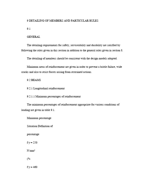
9 DETAILING OF MEMBERS AND PARTICULAR RULES9.1GENERALThe detailing requirements for safety, serviceability and durability are satisfied by following the rules given in this section in addition to the general rules given in section 8.The detailing of members should be consistent with the design models adopted.Minimum areas of reinforcement are given in order to prevent a brittle failure, wide cracks and also to resist forces arising from restrained actions.9.2 BEAMS9.2.1 Longitudinal reinforcement9.2.1.1 Minimum percentages of reinforcementThe minimum percentages of reinforcement appropriate for various conditions of loading are given in table 9.1.Minimum percentageSituation Definition ofpercentagef y = 250N/mm²(%f y = 460N/mm²(%Tension reinforcementSections subjected mainly to pure tensionSections subjected to flexure:100A s/A c0.8 0.45 (i flanged beams, web in tension: b w/b < 0.4 b w/b≥ 0.4 100A s/b w h100A s/b w h0.320.240.180.13(ii flanged beams, flange in tension:T-beam L-beam 100A s/b w h100A s/b w h0.480.360.260.20(iii rectangular section 100A s/A c0.24 0.13 Compression reinforcement (where such reinforcement is required for theultimate limit stateGeneral rule 100A sc/A cc0.4 0.4Simplified rules for particular cases:(i rectangular beam 100Asc/A c0.2 0.2(ii flanged beamflange in compression web in compression 100A sc/bh f100A sc/b w h0.40.20.40.2Transverse reinforcement in flanges offlanged beams(provided over full effective flange width neartop surface to resist horizontal shear100 A st/h f l0.15 0.15Notes:1. The minimum percentages of reinforcement should be increased where necessary to meet theductility requirements given in clause 9.9.Table 9.1 - Minimum percentages of reinforcementSections containing less reinforcement than that given by table 9.1 should be considered as unreinforced.9.2.1.2 Side bars for beams exceeding 750 mm overall depth.The minimum size of longitudinal bars in side faces of beams to control cracking should be not less than √(s b b /f y where s b is the bar spacing and b the breadth of the section at the point considered, or500 mm if b exceeds 500 mm.The spacing should not exceed 250 mm and the bars should be distributed over a distance of two-thirds of the beam’s overall depth measured from its tension face.9.2.1.3 Maximum areas of reinforcementNeither the area of tension reinforcement nor the area of compression reinforcement should exceed 4% of the gross cross-sectional area of the concrete.At laps, the sum of the reinforcement sizes in a particular layer should not exceed 40% of the breadth of the section at that location.9.2.1.4 Maximum distance between bars in tensionThe clear horizontal distance between adjacent bars, or groups, near the tension face of a beam should not be greater than:clear spacing ≤ 70 000 βb /f y ≤ 300 mm 9.1where:βbis the redistribution ratio:tion redistribu before section the at moment tionredistribu after section the at moment from the respective maximum moments diagram.Alternatively, the clear spacing may be assessed from the relationship: clear spacing ≤ 47 000/f s ≤ 300 mm9.2where:f s is the estimated service stress in the reinforcement and may be obtained from:bprovs,req s,y s 132β×=A A f f 9.3The distance between the face of the beam and the nearest longitudinal bar in tension should not be greater than half the clear distance determined above.9.2.1.5 Other detailing arrangementsIn monolithic construction, even when simple supports have been assumed in design, the section at supports should be designed for a bending moment arising from partial fixity of at least 15% of the maximum bending in the span.(Note, the minimum area of longitudinal reinforcement defined in clause 9.2.1.1 applies.At intermediate supports of continuous beams, the total area of tension reinforcement A s of a flanged cross-section may be spread over the effective width of flange (see clause 5.2.1.2 (a provided that at least 50% of A s is placed within the web width (see figure 9.19.2.1.6 Curtailment of tension reinforcementExcept at end supports (see clause 9.2.1.7 in every flexural member every bar should extend beyond the point at which in theory it is no longer needed, for a distance at least equal to the greater of:• the effective depth of the member; or •12 times the bar diameter.In addition for a bar in the tension zone, one of the following distances for all arrangements of design ultimate load should be considered:• an anchorage length appropriate to its design strength (0.87f y from the point at which it is no longer required to assist in resisting the bending moment; or• to the point where the design shear capacity of the section is greater than twice the design shear force at that section; or• to the point where other bars continuing past that point provide double the area required to resist the design bending moment at that section.The point at which a bar is no longer required is the point where the design resistance moment of the section, considering only the continuing bars, is equal to the design moment.As curtailment of substantial areas of reinforcement at a single section can lead to the development of large cracks at that point, it is therefore advisable to stagger the curtailment points in heavily reinforced members.Figure 9.1 - Placing of tension reinforcement in flanged cross-section9.2.1.7 Anchorage of bars at a simply-supported end of a beamAt a simply-supported end of a member half the calculated mid-span bottom reinforcement should be anchored by one of the following:• an effective anchorage length equivalent to 12 times the bar diameter beyond the centre-line of the support. No bend or hook should begin before the centre of the support; or • an effective anchorage length equivalent to 12 times the bar diameter p lus d/2 from the face of the support, where d is the effective depth of member. No bend or hook shouldbegin before d/2 from the face of the support.9.2.1.8 Anchorage of bottom reinforcement at internal supportsAt an intermediate support of a continuous member 30% of the calculated mid-span bottom reinforcement should be continuous through the support.9.2.1.9 Cantilever extensionsWhere a cantilever forms an extension beyond the end support of a continuous beam or slab, care should be taken to ensure that the top steel in the adjacent span extends beyond the point of contraflexure.9.2.1.10 Containment of compression reinforcementThe recommendations given in clause 9.5.2.2 for columns will apply also to beams.9.2.2 Shear reinforcementThe shear reinforcement may consist of a combination of:• links enclosing the longitudinal tension reinforcement and the compression zone;• bent-up bars; and• cages or ladders (see figure 9.2 which are cast in without enclosing the longitudinalreinforcement but are properly anchored in the compression and tension zones.Links should be effectively anchored in accordance with clause 8.5. A lap joint on the leg near thesurface of the web is permitted provided that the link is not required to resist torsion.At least 50%of the necessary shear reinforcement should be in the form of links.The minimum area of shear reinforcement for the whole length of a beam is given by:A sv≥ 0.4 b v s v/(0.87f yv9.4The maximum spacing of the links in the direction of the span should not exceed 0.75d. At right-angles to the span, the horizontal spacing should be such that no longitudinal tension bar is morethan 150 mm from a vertical leg.The longitudinal spacing of bent-up bars (see figure 6.2 should not exceed s b,max, as given byequation 9.5.s b,max = 0.6d(1 + cotα 9.5 where:αis the inclination of the bent-up bars to the longitudinal axis.Figure 9.2 - Examples of shear reinforcement9.2.3 Torsion reinforcementTorsion links should be closed and be anchored by means of laps or hooked ends, see figure 9.3, andshould form an angle of 90° with the axis of the structural element.Figure 9.3 - Torsion link arrangementsTorsion reinforcement should comply with the provisions of clauses 6.3.5 to 6.3.9.SLABS9.3 SOLIDThis section applies to one-way and two-way solid slabs.9.3.1 Flexural reinforcement9.3.1.1 General(a Minimum reinforcementThe following minimum percentages of total longitudinal reinforcement should be provided ineach direction:• f y = 250 N/mm2: 0.24% of concrete cross-sectional area; and• f y = 460 N/mm2: 0.13% of concrete cross-sectional area.Generally secondary transverse reinforcement of not less than 20% of the principalreinforcement should be provided in one-way slabs. In areas near supports transversereinforcement to principal top bars is not necessary where there is no transverse bendingmoment.(b Reinforcement spacingThe maximum spacing of bars should comply with the following requirements: • for the principal reinforcement, 3h≤ 400 mm; and• for the secondary reinforcement, 3.5h≤ 450 mm.In areas with concentrated loads or areas of maximum moment those provisions becomerespectively:• for the principal reinforcement, 2h≤ 250 mm; and• for the secondary reinforcement, 3h≤ 400 mm.In addition, unless crack widths are checked by direct calculation, the following rules willensure adequate control of cracking for slabs subjected to normal internal and externalenvironments:No further check is required on bar spacing if either:• h≤ 250 mm (grade 250 stee l;• h≤ 200 mm (grade 460 steel; or• the percentage of required tension reinforcement (100A s/bd is less than 0.3%.Where none of these three conditions apply, the bar spacings should be limited to the valuescalculated in clause 9.2.1.4 for slabs where the required reinforcement percentage exceeds1% or the values calculated in clause 9.2.1.4 divided by the reinforcement percentage forpercentage less than 1.In slabs where the amount of redistribution is unknown, βb may be assumed to be minus 15%for support moments and zero for span moments.When reinforcement is needed to distribute cracking arising from shrinkage and temperatureeffects, the recommendations given in clause 9.6.5 for plain walls should be followed.9.3.1.2 Curtailment of tension reinforcementCurtailing and anchoring reinforcement may be carried out in accordance with clause 9.2.1.6 for beams.9.3.1.3 Reinforcement at end supportsIn simply supported slabs or end support of continuous slabs, half the calculated span reinforcement should be anchored into the support in accordance with section 8.4 and the provisions of clause9.2.1.7 for beams.If the design ultimate shear stress at the face of the support is less than half the appropriate value, νc, recommended in clause 6.1.2.5, a straigh t length of bar beyond the centreline of the support equal to either one-third of the support width or 30 mm, whichever is the greater may be considered as effective anchorage.Negative moments due to partial fixity may arise which could lead to cracking. To control this, an amount of top reinforcement capable of resisting at least 50% of the maximum mid-span moment, but not less than the minimum given in clause 9.3.1.1, should be provided at the support. It should havea full effective tensile anchorage into the support and extend not less than 0.15l or45 times the bardiameter into the span.9.3.1.4 Bottom reinforcement internal supportsAt an intermediate support of a slab 40% of the calculated mid-span bottom reinforcement should be continuous through the support.9.3.1.5 Corner reinforcementIf the detailing arrangements at a support are such that lifting of the slab at a corner is restrained, suitable reinforcement should be provided. See clause 6.1.3.3(c and (d.9.3.1.6 Reinforcement at free edgesAlong a free (unsupported edge, a slab should normally contain longitudinal and transverse reinforcement, generally arranged as shown in figure 9.4.The normal reinforcement provided for a slab may act as edge reinforcement.Figure 9.4 - Edge reinforcement for a slab9.3.2 Shear reinforcementShear reinforcement, if required for solid slabs, ribbed slabs and flat slabs, should comply with the provisions of clauses 6.1.3.5, 6.1.4.4 or 6.1.5.7 as appropriate.It is difficult to bend and fix shear reinforcement and assure its effectiveness in slabs less than 200mm thick. Therefore, shear reinforcement should not be used in such slabs.9.4 CANTILEVERED PROJECTING STRUCTURES9.4.1 Minimum reinforcementThe minimum percentage of top tension longitudinal reinforcement based on the gross cross-sectional concrete area should be 0.25% for all reinforcement grades. The minimum diameter of this principal reinforcement should be 10 mm.For areas of minimum reinforcement at other locations within a projecting structure refer to sections9.2 or 9.3 as appropriate.9.4.2 Reinforcement spacingThe centre-to-centre spacing of the top tension longitudinal bars should not be more than 150 mm.9.4.3 Anchorage of tension reinforcementA full anchorage length beyond the centreline of the supporting member should be provided for toptension reinforcement of a cantilevered projecting structure. No reduction in anchorage bond length due to actual bar stress shall be permitted. See section 1.4 for definition of a cantilevered projecting structure.COLUMNS9.5This clause deals with columns for which the larger dimension h c is not greater than 4 times the smaller dimension b c.9.5.1 Longitudinal reinforcementThe area of total longitudinal reinforcement based on the gross cross-sectional area of a column should not be less than 0.8%. See clause 9.9.2 for ductility requirement.Bars should have a diameter of not less than 12 mm.The minimum number of longitudinal bars in a column should be four in rectangular columns and six in circular columns. In columns having a polygonal cross-section, at least one bar should be placed at each corner.The longitudinal reinforcement should not exceed the following amounts, calculated as percentages of the gross cross-sectional area of the concrete:• ver tically-cast columns - 6%;• horizontally-cast columns - 8%; and• laps in vertically-or horizontally-cast columns - 10%.At laps, the sum of the reinforcement sizes in a particular layer should not exceed 40% of the breadth of the section at that location.9.5.2 Transverse reinforcement9.5.2.1 GeneralThe diameter of the transverse reinforcement (links, loops or helical spiral reinforcement should not be less than 6 mm or 1/4 the diameter of the largest longitudinal bar, whichever is the greater. The diameter of wires or welded mesh fabric when used for transverse reinforcement should not be less than 5 mm.The spacing of transverse reinforcement along a column should not exceed 12 times the diameter of the smallest longitudinal bar.9.5.2.2 Rectangular or polygonal columnsEvery corner bar, and each alternate bar (or bundle in an outer layer of reinforcement should be supported by a link passing around the bar and having an included angle of not more than 135° (see figure 9.5a. No bar within a compression zone should be further than 150 mm from a restrained bar.Links should be adequately anchoraged by means of hooks bent though an angle of not less than 135° (see figure 9.5b.9.5.2.3 Circular columnsSpiral transverse reinforcement should be anchored by either welding to the previous turn, in accordance with clause 8.7, or by terminating the spiral with at least a 135º hook bent around a longitudinal bar and the hook being no more than 25 mm from the previous turn.Circular links should be anchored by either a mechanical connection or welded lap, in accordance with clause 8.7, or by terminating each end of the link with at least a 135ºhook bent around a longitudinal bar and overlapping the other end of the link (see figure 9.5c.Spiral or circular links should not be anchored by straight lapping.Figure 9.5 - Column transverse reinforcementWhere the direction of the column longitudinal bars change, (e.g. at changes in column size, the spacing of transverse reinforcement should be calculated, taking account of the lateral forces involved.These effects may be ignored if the change of direction is less than or equal to 1 in 12.9.6WALLSGeneral9.6.1This clause refers to reinforced concrete walls with a length to thickness ratio of 4 or more and in which the reinforcement is taken into account in the strength analysis. For walls subjected predominantly to out-of-plane bending the rules for slabs apply (see section 9.3.reinforcementVertical9.6.2The minimum percentage of vertical reinforcement based on the concrete cross-sectional area of a wall is 0.4%. Where this minimum area of reinforcement controls in the design, half of the area should be located at each face.The area of vertical reinforcement should not exceed 4% of the concrete cross-sectional area of a wall.The distance between two adjacent vertical bars shall not exceed 3 times the wall thickness or 400 mm whichever is the lesser.9.6.3 Horizontal reinforcementWhere the main vertical reinforcement is used to resist compression and does not exceed 2% of the concrete area, at least the following percentages of horizontal reinforcement should be provided, depending upon the characteristic strength of that reinforcement:• f y = 250 N/mm2: 0.30% of concrete cross-sectional area; and• f y = 460 N/m m2: 0.25% of concrete cross-sectional area.These horizontal bars should be evenly spaced at no more than 400 mm. The diameter should be not less than one-quarter of the size of the vertical bars and not less than 6 mm.9.6.4 Transverse reinforcementWhen the vertical compression reinforcement exceeds 2%, links at least 6 mm or one-quarter the size of the largest compression bar should be provided through the thickness of the wall. The spacing of links should not exceed twice the wall thickness in either the horizontal or vertical direction. In the vertical direction it should be not greater than 16 times the bar diameter. All vertical compression bars should be enclosed by a link. No bar should be further than 200 mm from a restrained bar, at which a link passes round the bar with an included angle of not more than 90°.9.6.5 Plain wallsReinforcement may be needed in plain walls to control cracking due to flexure or thermal and hydration shrinkage. Wherever provided, the minimum quantity of reinforcement in each direction should be at least:• f y = 250 N/mm2: 0.30% of concrete cross-sectional area; and• f y = 460 N/mm2: 0.25% of concrete cross-sectional area.If necessary in walls exceeding 2 m in length and exposed to the weather, reinforcement should be provided in both horizontal and vertical directions. It should consist of small diameter bars, relatively closely spaced, with adequate cover.For internal plain walls it may be sufficient to provide reinforcement only at that part of the wall where junctions with floors and beams occur. When provided it should be dispersed half near each face.Nominal reinforcement around openings should be considered.9.7 FOUNDATIONS9.7.1 Pile capsThe distance from the outer edge of the pile to the edge of the pile cap should be such that the forces in the pile cap can be properly anchored. The expected deviation of the pile on site should be taken into account.The main tensile reinforcement to resist the action effects should be concentrated in the stress zones between the tops of the piles. If the area of this reinforcement is at least equal to the minimum reinforcement, evenly distributed bars along the bottom surface of the member may be omitted. Alsothe sides and the top surface of the member may be unreinforced if there is no risk of tension developing in these parts of the members. The minimum reinforcement as shown in Table 9.1 should be observed.Welded transverse bars may be used for the anchorage of the tension reinforcement. In this case the transverse bar may be considered to be part of the transverse reinforcement in the anchorage zone of the reinforcement bar considered.The compression caused by the support reaction from the pile may be assumed to spread at 45° degree angles from the edge of the pile. This compression may be taken into account when calculating the anchorage length.The compression bond stresses that develop on starter bars within bases or pile caps need not be checked provided:• the starter bars extend down to the level of the bottom reinf orcement;• the pile cap base has been designed for moments and shear in accordance with section6.7.9.7.2 Column and wall footingsThe main reinforcement should be anchored in accordance with the requirements of sections 8.4 and8.5.If the action effects cause tension at the upper surface of the footing, the resulting tensile stresses should be checked and reinforced as necessary.The minimum reinforcement as shown in Table 9.1 should be observed.9.7.3 Tie beamsTie beams may be used to eliminate the eccentricity of loading of the foundations. The beams should be designed to resist the resulting bending moments and shear forces.Tie beams should also be designed for a minimum downward load of 10 kN/m if the action of compaction machinery can cause effects to the beams.9.8CORBELSGeneral9.8.1The design of corbels may be based on strut-and-tie models provided that equilibrium and strength requirements are satisfied. The horizontal link requirement of clause 9.8.3 will ensure satisfactory serviceability performance.9.8.2 Reinforcement anchorageAt the front face of the corbel, the reinforcement should be anchored either by:• welding to a transverse bar of equal strength and diameter. In this case the bearing area of the load should stop short of the transverse bar by a distance equal to the cover of thetie reinforcement; or• bending back the bars to form a loop. In this case the bearing area of the load should not project beyond the straight portion of the bars forming the main tension reinforcement.9.8.3 Shear reinforcementShear reinforcement should be provided in the form of horizontal links distributed in the upper 2/3 of the effective depth of the root of the corbel. This reinforcement should not be less than half the area of the main tension reinforcement and should be adequately anchored (see figure 9.6.Figure 9.6 - Typical corbel detailing9.8.4 Resistance to horizontal forceAdditional reinforcement connected to the supported member should be provided to transmit this force in its entirety.9.9 DETAILING FOR DUCTILITYBeams9.9.19.9.1.1 Longitudinal reinforcement(a Maximum and minimum percentages of reinforcementThe minimum percentage of reinforcement in a beam is to be in accordance with table 9.1,however not less than 0.3%.The maximum area of tension reinforcement should not exceed 2.5% of the gross cross-sectional area of the concrete. At any section of a beam within a critical zone the compressionreinforcement should not be less than one-half of the tension reinforcement at the samesection.(b SpacingThe maximum clear distance between adjacent bars in tension should not exceed the limitsstated in clause 9.2.1.4.(c Anchorage into exterior column When longitudinal beam bars are anchored in cores of exterior columns or beam stubs, the anchorage for tension shall be deemed to commence at of the relevant depth of the column or 8 times the bar diameter whichever is less, from the face at which the beam bar enters the column. Where it can be shown that the critical section of the plastic hinge is at a distance of at least the beam depth or 500 mm, whichever is less, from the column face, the anchorage length may be considered to commence at the column face. For the calculation of anchorage length the bars must be assumed to be fully stressed. Notwithstanding the adequacy of the anchorage of a beam bar in a column core or a beam stub, no bar shall be terminated without a vertical 90 standard hook or equivalent anchorage device as near as practically possible to the farside of the column core, or the end of the beam stub where appropriate, and not closer than of the relevant depth of the column to the face of entry. Top beam bars shall only be bent down and bottom bars must be bent up. (d Splices Full strength welded splices may be used in any location. For laps and mechanical couplers no portion of the splice shall be located within the beam/column joint region or within one effective depth of the member from the critical section of a potential plastic hinge in a beam where stress reversals in lapped bars could occur. Reinforcement shall not be lapped in a region where reversing stresses at the ultimate limit state may exceed 0.6fy in tension or compression unless each lapped bar is confined by links or ties so that φf y Atr ≥ s 48 f yt wher e: Atr 9.6 smaller of area of transverse reinforcement within a spacing s crossing a plane of splitting normal to concrete surface containing extreme tension fibres, or total area of transverse reinforcement normal to the layers of bars within a spacing s, divided by n, 2 mm , maximum spacing of transverse reinforcement within the lap length, characteristic yield strength of the transverse reinforcement. s fyt Mechanical splices shall be tested through 8 full cycles of loading to a maximum stress of 0.95fy in the bar, and at maximum load in both tension and compression shall show a change of length, measured over the full length of the connection system, not more than 10% in excess of the extension in an equal length of unspliced bar. Splices not satisfying this stiffness 2 requirement shall be used only if they are staggered so that no more than /3 of the reinforcement area is spliced within any 900 mm length of the member. (e Curtailment The distribution and curtailment of the longitudinal flexural reinforcement shall be such that the flexural overstrength of a section can be attained at critical sections in potential plastic hinge regions. 9.9.1.2 Transverse reinforcement (a Spacing The centre-to-centre spacing of links or ties along a beam shall not exceed the smaller of the least lateral dimension of the cross section of the beam or 16 times the longitudinal bar diameter. Links or ties shall be arranged so that every corner and alternate longitudinal bar that is required to function as compression reinforcement shall be restrained by a leg. (b Anchorage Links should beadequately anchored by means of 135° or 180° hooks in accordance with clause 8.5. Anchorage by means of 90° hooks or welded cross bars is not permitted. 1389.9.2 9.9.2.1 Columns Longitudinal reinforcement (a Maximum and minimum areas of reinforcement The area of longitudinal reinforcement based on the gross concrete area of a column shall not be less than 0.8%. The area of longitudinal reinforcement shall not be greater than 4% of the gross concrete area except that at laps the area may increase to 5.2%. In any row of bars the smallest bar diameter used shall not be less than /3 of the largest bar diameter used. When columns are designed to develop plastic hinges in the end regions, the maximum diameter of column bars passing through the beams shall satisfy: 2 φ≤ 3.2h 0.8 f cu fy 9.7 where: h is the overall beam depth. When columns are not intended to develop plastic hinges in the end regions, the maximum diameter of longitudinal column bars at any level may exceed that given by equation 9.7 by 25%. (b Spacing For longitudinal bars in potential plastic hinge regions, the cross-linked bars shall not be 1 spaced further apart between centres than the larger of /4 of the adjacent lateral column dimension or 200 mm. (c Anchorage of column reinforcement Where column bars terminate in beam-column joints or joints between columns and foundation members and where a plastic hinge in the column may be expected, the anchorage of the longitudinal column bars into the joint region shall be assumed to commence at of the depth of the beam or 8 bar diameters, whichever is less, from the face at which the column bar enters the beam or foundation member. When it is shown that a column plastic hinge adjacent to the beam face cannot occur, the development length shall be considered to commence from the beam face. Notwithstanding the adequacy of the anchorage of a column bar into an intersecting beam, no column bar shall be terminated in a joint area without a horizontal 90 standard hook or equivalent anchorage device as near the far face of the beam as practically possible, and not closer than of the depth of the beam to the face of entry. Unless a column is designed to resist only axial forces, the direction of the horizontal leg of the bend must always be towards the far face of the column. (d Splices Full strength welded splices may be used in any location. For laps and。


混凝土结构设计规范非标设备结构设计规范篇一非标设备结构设计规范v1 东莞力士自动化设备有限公司1、结构件各自分工,功能确定;机构稳定可靠,满足使用要求; 2.机构定位准确;3、重复精度满足使用要求;4、机架、机座及零部件刚性足够,工作时不致于变形(如气缸座等); 5.运动无干扰A在零件的所有自由度内(360°旋转、摆动、上下、左右)无碰撞、阻挡(包括电线、气管等),应预留尽可能大的空间; B 必要时,螺丝采用沉头或平头。
二、安全措施1、设计防止意外事故的防护罩(如皮带、运动机构); 2.必要时,设计双手操作按钮(如冲床等运动机构); 3.必要时,设置安全光栅;4、设置极限位置限位器(机械限位与Sensor限位双保险); 5.必要时,马达装扭力限制器,防止过载烧毁; 6.必要时Sensor加保护罩。
三、安装调试方便1、精度要求高的较大机架,不便加工的,基座面板采用可调支承(大直径细牙螺柱),降低成本; 2.螺纹联接部位要预留尽较大的安装维修空间;3、有定位精度要求的零部件,应尽可能延伸到基座面板上,不可直接安装在焊接机架上。
四、气(油)管线要求1、机架及基座面板上要多处预穿留管线孔,减少安装现场开孔的困难;2、对大流量气动元件,要考虑供气管直径是否足够,并在必要时设置储气罐; 3.需旋转的气管应采用旋转接头;4、对于长距离,多管路系统,为方便维修,应采用可拔插的对接式接头。
五、电气线路要求1、机架及基座面板上要多处预留马达及Sensor穿线孔,需往复长距离移动部位应采用拖链; 2.Sensor座要可调;3、对于小电流低压电器,为方便维修,可采用对接式接头; 4.必要时,电线应采取防油防爆措施(套金属软管)。
六.滑动转动部位的润滑措施1、导轨等滑动部位,及轴承等转动部位,应设计润滑结构,装注油咀。
2.必要时,设置防尘结构(如采用带密封盖轴承,装密封圈等)。
七。
其他要求1、机器结构满足加工工艺要求,便于制造; 2.结构简明;; 3.符合经济性要求;4.符合美学原理;5、符合噪声要求(如同步带传动比齿轮传动噪声低); 6.符合要求(防尘、无污染)。
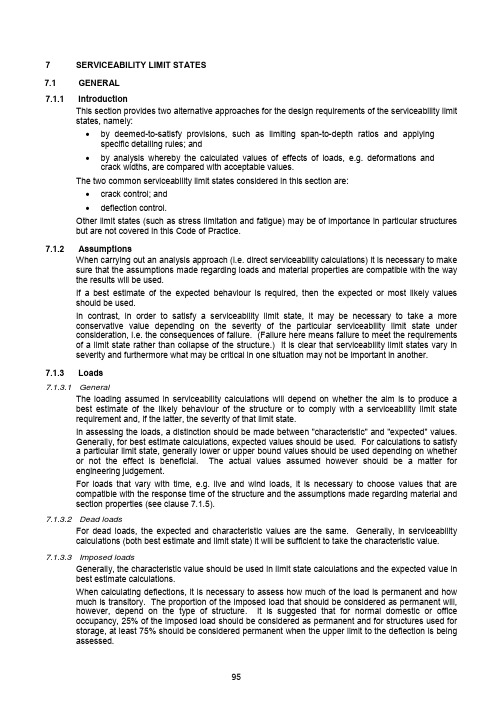
7 SERVICEABILITY LIMIT STATESGENERAL7.1Introduction7.1.1This section provides two alternative approaches for the design requirements of the serviceability limit states, namely:• by deemed-to-satisfy provisions, such as limiting span-to-depth ratios and applying specific detailing rules; and• by analysis whereby the calculated values of effects of loads, e.g. deformations and crack widths, are compared with acceptable values.The two common serviceability limit states considered in this section are:• crack control; and• deflection control.Other limit states (such as stress limitation and fatigue) may be of importance in particular structures but are not covered in this Code of Practice.7.1.2AssumptionsWhen carrying out an analysis approach (i.e. direct serviceability calculations) it is necessary to make sure that the assumptions made regarding loads and material properties are compatible with the way the results will be used.If a best estimate of the expected behaviour is required, then the expected or most likely values should be used.In contrast, in order to satisfy a serviceability limit state, it may be necessary to take a more conservative value depending on the severity of the particular serviceability limit state under consideration, i.e. the consequences of failure. (Failure here means failure to meet the requirements of a limit state rather than collapse of the structure.) It is clear that serviceability limit states vary in severity and furthermore what may be critical in one situation may not be important in another.Loads7.1.37.1.3.1 GeneralThe loading assumed in serviceability calculations will depend on whether the aim is to produce a best estimate of the likely behaviour of the structure or to comply with a serviceability limit state requirement and, if the latter, the severity of that limit state.In assessing the loads, a distinction should be made between "characteristic" and "expected" values.Generally, for best estimate calculations, expected values should be used. For calculations to satisfya particular limit state, generally lower or upper bound values should be used depending on whetheror not the effect is beneficial. The actual values assumed however should be a matter for engineering judgement.For loads that vary with time, e.g. live and wind loads, it is necessary to choose values that are compatible with the response time of the structure and the assumptions made regarding material and section properties (see clause 7.1.5).7.1.3.2 Dead loadsFor dead loads, the expected and characteristic values are the same. Generally, in serviceability calculations (both best estimate and limit state) it will be sufficient to take the characteristic value.7.1.3.3 Imposed loadsGenerally, the characteristic value should be used in limit state calculations and the expected value in best estimate calculations.When calculating deflections, it is necessary to assess how much of the load is permanent and how much is transitory. The proportion of the imposed load that should be considered as permanent will, however, depend on the type of structure. It is suggested that for normal domestic or office occupancy, 25% of the imposed load should be considered as permanent and for structures used for storage, at least 75% should be considered permanent when the upper limit to the deflection is being assessed.7.1.4 Analysis of structure for serviceability limit statesIn general, it will be sufficiently accurate to assess the moments and forces in members subjected to their appropriate loadings for the serviceability limit states using an elastic analysis. Where a single value of stiffness is used to characterise a member, the member stiffness may be based on the concrete section. In this circumstance it is likely to provide a more accurate picture of the moment and force fields than will the use of a cracked transformed section, even though calculation shows the members to be cracked. Where more sophisticated methods of analysis are used in which variations in properties over the length of members can be taken into account, it will frequently be more appropriate to calculate the stiffness of highly stressed parts of members on the basis of a cracked transformed section.7.1.5 Material properties for the calculation of curvature and stressesFor checking serviceability limit states, the modulus of elasticity of the concrete should be taken as the value given in table 3.2. The modulus of elasticity may be corrected for the age of loading where this is known. Where a ‘best estimate’ of the curvature is required, an elastic modulus appropriate to the expected concrete strength may be used. Attention is, however, drawn to the large range of values for the modulus of elasticity that can be obtained for the same cube strength. It may therefore be appropriate to consider either calculating the behaviour using moduli at the ends of the ranges to obtain an idea of the reliability of the calculation or to have tests done on the actual concrete to be used. Refer to section 3 for appropriate values for creep and shrinkage in the absence of more direct information.7.2CRACKING7.2.1GeneralCracking shall be limited to an extent that will not impair the proper functioning or durability of the structure or cause its appearance to be unacceptable. Cracking is normal in reinforced concrete structures subjected to flexure, shear, torsion or tension resulting from either direct loading or restraint of imposed deformations.Appropriate limitations, taking into account of the proposed function and nature of the structure and the costs of limiting cracking, should be established. It may be assumed that the limitations of the maximum estimated crack width given in table 7.1 will generally be satisfactory for reinforced concrete members in buildings with respect to appearance and durability.Reinforced members and prestressed members with unbonded tendons Prestressed members with bonded tendonsExposure conditionQuasi-permanent loadcombinationFrequent load combination1, 2, and 3 0.3 mm(1) 0.2mm4 0.3 mm 0.2 mmWater retainingstructures(2)0.2 mm -Notes:1. For exposure condition 1, crack width has no influence on durability and this limit is set to guarantee acceptableappearance. In the absence of appearance conditions this limit may be relaxed.2. Water retaining structures referred to here are water tanks and the like used in general building works and not meantto include large civil water retaining structures.Table 7.1 - Limitations of maximum estimated surface crack widthsSince the bar spacing rules given in section 9 for particular members have to ensure that cracking isnot serious in the worst likely practical situation, it will almost always be found that wider bar spacingscan be used if the crack widths are checked explicitly. This will be particularly true for fairly shallowmembers.7.2.2 Control of cracking without direct calculation (deemed-to-satisfy)If the detailing rules prescribed in sections 8 and 9 with respect to minimum reinforcement areas andbar spacings are complied with, no further checks on crack widths are usually necessary.However, should it be considered appropriate to estimate crack widths, the approach in clause 7.2.3 may be followed.7.2.3Assessment of crack widthsThe widths of flexural cracks at a particular point on the surface of a member depend primarily on three factors:• the proximity to the point considered of reinforcing bars perpendicular to the cracks; • the proximity of the neutral axis to the point considered; and •the average surface strain at the point considered.Equation 7.1 gives a relationship between crack width and these three principal variables which gives acceptably accurate results in most normal design circumstances; however, the formula should be used with caution in members subjected dominantly to an axial tension.It should be remembered that cracking is a semi-random phenomenon and that an absolute maximum crack width cannot be predicted. The formula is designed to give a width with an acceptably small chance of being exceeded, thus an occasional crack slightly larger than the predicted width should not be considered as cause for concern. However, should a significant number of cracks in a structure exceed the calculated width, reasons other than the statistical nature of the phenomenon should be sought to explain their presence.Provided the strain in the tension reinforcement is limited to 0.8f y /E s , the design surface crack width, which should not exceed the appropriate value given in clause 7.2.1 may be calculated from the following equation:Design surface crack width ω (213xh c a a −−+=min cr mcr ε7.1where:a cr is the distance from point considered to the surface of the nearest longitudinal bar,εm is the average strain at the level where the cracking is being considered,c min is the minimum cover to the tension steel.The average strain εm may be calculated on the basis of the assumptions given in clause 7.3.6. Alternatively, as an approximation, it will normally be satisfactory to calculate the steel stress on the basis of a cracked section and then reduce this by an amount equal to the tensile force generated by the stress distribution defined in clause 7.3.6 (a) acting over the tension zone divided by the steel area. For a rectangular tension zone, this gives:()()()x d A E x a x h b −−−−=s s t 1m 3'εε 7.2where:a ’ is the distance from the compression face to the point at which the crack width is being calculated,b tis the width of the section at the centroid of the tension steel.In this 7.2 for cases where the whole section is in tension, an effective value of (h - x ) can be estimated by interpolation between the following limiting conditions:• where the neutral axis is at the most compressed face, (h - x ) = h (i.e. x = 0); and •for axial tension, (h - x ) = 2h .A negative value for εm indicates that the section is uncracked.In assessing the strains, the modulus of elasticity of the concrete should be taken as half the instantaneous values.Where it is expected that the concrete may be subject to abnormally high shrinkage (> 0.0006), εm should be increased by adding 50% of the expected shrinkage strain; otherwise, shrinkage may be ignored.Note: This approach makes a notional allowance for long-term effects.7.2.4 Earlythermalcracking7.2.4.1 GeneralIn pours that are subjected to either internal or external restraint, thermal stresses may develop which can cause cracking. Cracking can occur through two different mechanisms.(a) Internal temperature gradientsCracking due to differential temperature changes is most common in massive pours. Since thelow thermal conductivity of concrete prevents rapid heat dissipation, the temperature in themass of concrete increases. The concrete surface, in direct contact with the environment,loses heat more quickly and therefore undergoes a much lower rise in temperature. Theresulting expansion of the hot core, if excessive, can stretch the cooler surface zone to theextent that cracking occurs. During subsequent cooling, the opposite effect may occur causinginternal cracking of the central zone.(b) External restraint during coolingCracking resulting from restraint to thermal movement most commonly occurs in walls cast intorigid bases. During the temperature rise period, the concrete has a relatively low elasticmodulus and the compressive stresses due to restrained expansion are easily relieved bycreep. During cooling, the concrete matures and, when the thermal contraction is restrained,the tensile stresses generated are less easily relieved. These can be of sufficient magnitude tocause cracking which commonly occurs at the half or one-third points along a bay. In theextreme case of a fully restrained element, a change in temperature of the order of only 10°Ccan result in cracking. Therefore, the high temperature rises which can result in long-termstrength reductions are not essential to the promotion of cracks. However, if there was norestraint, the concrete would contract without cracking.Typical values of restraint recorded for a range of pour configurations have been given in table7.2. For most situations there is always some degree of restraint but complete restraint is veryrare. Even when a wall is cast on to a nominally rigid foundation, the restraint is unlikely toexceed a value of R equal to 0.70. To minimize restraint, infill bays should be avoidedwherever possible and the pour provided with a free end to accommodate thermal movement.Pour configuration Restraint factor(R)Thin wall cast on to massive concrete base 0.6 to 0.8 at base0.1 to 0.2 at topMassive pour casting into blinding 0.1 to 0.2Massive pour cast on to existing mass concrete 0.3 to 0.4 at base0.1 to 0.2 at topSuspended slabs 0.2 to 0.4Infill bays, i.e. rigid restraint 0.8 to 1.0Table 7.2 - Values of external restraint recorded in various structures7.2.4.2 Estimating early thermal crack widthsThe restrained component of the thermal strain εr, which will be accommodated by cracks is given by the following equation:εr = 0.8α(Τ1 + Τ2)R7.3 where:R is the restraint factor (see table 7.2),αis the coefficient of thermal expansion of concrete,T1is the short-term fall in temperature from hydration peak to ambient conditions,T2is the long-term fall in temperature from ambient to seasonal minimum,εr is the strain accompanied by cracking.Crack widths may be estimated by substituting εr for εm in equation 7.1.Reinforcement that is present in the section for other purposes may be included as part of reinforcement necessary to satisfy the requirements for the control of early thermal cracking.7.3 DEFORMATIONS7.3.1 General considerationsThe deformation of a member or structure shall not be such that it adversely affects its proper functioning or appearance.Appropriate limiting values of deflection taking into account the nature of the structure, of the finishes, partitions and fixings and upon the function of the structure should be established.Deformations should not exceed those that can be accommodated by other connected elements such as partitions, glazing, cladding, services or finishes. In some cases limitation may be required to ensure the proper functioning of machinery or apparatus supported by the structure, or to avoid ponding on flat roofs.The appearance and general utility of the structure may be impaired when the calculated sag of a beam, slab or cantilever subjected to quasi-permanent loads exceeds span/250. The sag is assessed relative to the supports. Pre-camber may be used to compensate for some or all of the deflection but any upward deflection incorporated in the formwork should not generally exceed span/250.Deflections that could damage adjacent parts of the structure should be limited. For the deflection after construction, span/500 is normally an appropriate limit for quasi-permanent loads. Other limits may be considered, depending on the sensitivity of adjacent parts.The limit state of deformation may be checked by either:• limiting the span/depth ratio, according to clause 7.3.4; or• comparing a calculated deflection, according to clause 7.3.5, with a limit value.The actual deformations may differ from the estimated values, particularly if the values of applied moments are close to the cracking moment. The differences will depend on the dispersion of the material properties, on the environmental conditions, on the load history, on the restraints at the supports, ground conditions, etc.7.3.2 Excessive response to wind loadsExcessive accelerations under wind loads that may cause discomfort or alarm to occupants should be avoided. A static or dynamic analysis could be employed taking into account the pertinent features of the structure and its surroundings. Limiting deflection at the top of a building to H/500 when considering a static characteristic wind load should result in an acceptable environment for occupants in normal buildings.Partitions cladding and finishes, etc. need to be specifically detailed to allow for the anticipated relative lateral deflection in any one storey under the characteristic wind load.Where a dynamic analysis is undertaken, the maximum peak acceleration of the building should be assessed for wind speeds based on a 1-in-10-year return period of 10 minutes duration with the following limits:AccelerationFunction Peakm/s2Residential 0.15Office or hotel 0.25 m/s2The use of dampers on tall and slender buildings should be supported with dynamic analysis and specialist literature should be consulted.7.3.3 ExcessivevibrationExcessive vibration due to fluctuating loads that may cause discomfort or alarm to occupants, either from people or machinery, should be avoided. For a building floor structure with the natural frequency less than 6 Hz, or a footbridge superstructure with the natural frequency less than 5 Hz, a dynamic analysis may be desirable.Note: For further guidance reference should be made to specialist literature.7.3.4 Limiting deflection without direct calculation (deemed-to-satisfy)7.3.4.1 GeneralGenerally, it is not necessary to calculate the deflections explicitly as simple rules, for example limits to span-to-depth ratio may be formulated, which will be adequate for avoiding deflection problems in normal circumstances. More rigorous checks are necessary for members which lie outside such limits, or where deflection limits other than those implicit in simplified methods are appropriate.7.3.4.2 Span to effective depth ratioProvided that reinforced concrete beams or slabs in buildings are dimensioned so that they comply with the limits of span-to-depth ratio given in table 7.3, their deflections may be considered as not exceeding the limits set out in clause 7.3.1. No allowance has been made for any pre-camber in the derivation of these limits.Support condition RectangularbeamFlanged beamb w/b≤ 0.3One or two-wayspanning solidslabCantilever 75.57 Simply-supported 20 16 20 Continuous 26 21 26End span 23 18.5 23(2)Notes:1. The values given have been chosen to be generally conservative and calculation mayfrequently show that shallower sections are possible.2. The value of 23 is appropriate for two-way spanning slab if it is continuous over one longside.3. For two-way spanning slabs the check should be carried out on the basis of the shorter span.Table 7.3 - Basic span/effective depth ratio for reinforced concrete sections7.3.4.3 Long spansFor spans exceeding 10 m, table 7.3 should be used only if it is not necessary to limit the increase indeflection after the construction of partitions and finishes. Where limitation is necessary, the values intable 7.3 should be multiplied by 10/span except for cantilevers where the design should be justifiedby calculation.7.3.4.4 Modification of span/depth ratios for tension reinforcementDeflection is influenced by the amount of tension reinforcement and its stress. The span/effectivedepth ratio should therefore be modified according to the ultimate design moment and the servicestress at the centre of the span (or at the support in the case of a cantilever). Values ofspan/effective depth ratio obtained from table 7.3 should be multiplied by the appropriate factorobtained from table 7.4.Table 7.4 - Modification factor for tension reinforcement7.3.4.5 Modification of span/depth ratios for compression reinforcementCompression reinforcement also influences deflection and the value of the span/effective depth ratio obtained from table 7.3 modified by the factor obtained from table 7.4 may be multiplied by a further factor obtained from table 7.5.Table 7.5 - Modification factor for compression reinforcement7.3.4.6 Deflection due to creep and shrinkagePermissible span/effective depth ratios obtained from tables 7.3, 7.4 and 7.5 take account of normal creep and shrinkage deflection. If it is expected that creep or shrinkage of the concrete may be particularly high (e.g. if the free shrinkage strain is expected to be greater than 0.00075 or the creep coefficient greater than 3) or if other abnormally adverse conditions are expected, the permissible span/effective depth ratio should be suitably reduced. 7.3.5Calculation of deflection7.3.5.1 GeneralWhen it is deemed necessary to calculate the deflections of reinforced concrete members, it should be realised that there are a number of factors that may be difficult to allow for in the calculation which can have a considerable effect on the reliability of the result. These are as follows:• estimates of the restraints provided by supports are based on simplified and often inaccurate assumptions;• the precise loading, or that part which is of long duration, is unknown;•lightly reinforced members may well have a working load that is close to the cracking load for the members. Considerable differences will occur in the deflections depending on whether the member has or has not cracked; and•the effects on the deflection of finishes and partitions are difficult to assess and are often neglected.The dead load is the major factor determining the deflection, as this largely governs the long-term effects. Because the dead load is known to within quite close limits, lack of knowledge of the precise imposed load is not likely to be a major cause of error in deflection calculations. Imposed loading is highly uncertain in most cases; in particular, the proportion of this load which may be considered to be permanent and will influence the long-term behaviour (see clause 7.1.3.3).Finishes and rigid partitions added after the member is carrying its self-weight will help to reduce the long-term deflection of a member. As the structure creeps, any screed will be put into compression, thus causing some reduction in the creep deflection. The screed will generally be laid after the propping has been removed from the member, and so a considerable proportion of the long-term deflection will have taken place before the screed has gained enough stiffness to make a significant contribution. It is suggested that only 50% of the long-term deflection should be considered as reduceable by the action of the screed. If partitions of blockwork are built up to the underside of a member and no gap is left between the partition and the member, creep can cause the member to bear on the partition which, since it is likely to be very stiff, will effectively stop any further deflection along the line of the wall. If a partition is built on top of a member where there is no wall built up to the underside of the member, the long-term deflection will cause the member to creep away from the partition. The partition may be left spanning as a self-supporting deep beam that will apply significant loads to the supporting member only at its ends. Thus, if a partition wall is built over the whole span of a member with no major openings near its centre, its mass may be ignored in calculating long-term deflections.A suitable approach for assessing the magnitude of these effects is to calculate a likely maximum and minimum to their influence and take the average.7.3.5.2 Calculation of deflection from curvaturesThe deflected shape of a member is related to the curvatures by the equation:21dx a d r =x 7.4where:xr 1is the curvature at x , a is the deflection at x .Deflections may be calculated directly from this equation by calculating the curvatures at successive sections along the member and using a numerical integration technique. Alternatively, the following simplified approach may be used:br Kl a 12= 7.5where:l is the effective span of the member,br 1is the curvature at mid-span or, for cantilevers, at the support section, K is a constant that depends on the shape of the bending moment diagram.Table 7.6 gives values of the coefficient K for various common shapes of bending moment diagram. As the calculation method does not describe an elastic relationship between moment and curvature, deflections under complex loads cannot be obtained by summing the deflections obtained by separate calculation for the constituent simpler loads. A value of K appropriate to the complete load should be used.The calculation of the deflection of cantilevers requires very careful consideration in some circumstances. The usual formulae for the end deflection of cantilevers assume that the cantilever is rigidly fixed and is therefore horizontal at the root. In practice, this is by no means necessarily so, because the loading on the cantilever itself, or on other members to which the cantilever connects, may cause the root of the cantilever to rotate. If this root rotation is θ, the deflection of the tip of the cantilever will be decreased or increased by an amount l θ.Table 7.6 - Values of K for various bending moment diagramsThere are two sources of root rotation that may occur. First, rotation of the joint in the frame to which the cantilever connects. This problem will require attention only when the supporting structure is fairly flexible. Secondly, even where the cantilever connects to a substantially rigid structure, some root rotation will occur. This is because the steel stress, which is at a maximum at the root, should be dissipated into the supporting structure over some length of the bar embedded in the support. To allow for this, it is important to use the effective span of the cantilever as defined in clause 5.2.1.2 (b). If table 7.6 is used to assess the value of K by superposition, it may be assumed that the maximum deflection of a beam occurs at mid-span without serious errors being introduced.The problem of estimating the deflection of two-way spanning slabs is not simple. Before they crack, slabs will behave substantially as elastic, isotropic slabs. As soon as cracking occurs, the slabs become anisotropic, the amount of this anisotropy varying continuously as the loading varies, and so a reliable determination of the moment surface for the slab under any particular load is not normally practicable. Deflections of slabs are therefore probably best dealt with by using the ratios of span to effective depth. However, if the engineer feels that the calculation of the deflections of a slab is essential, it is suggested that the following procedure be adopted.A strip of slab of unit width is chosen such that the maximum moment along it is the maximum moment of the slab, i.e. in a rectangular slab, a strip spanning across the shorter dimension of the slab connecting the centres of the longer sides. The bending moments along this strip should preferably be obtained from an elastic analysis of the slab but may be assessed approximately by taking 70% of the moments used for the collapse design. The deflection of the strip is then calculated as though it was a beam. This method will be slightly conservative.7.3.6 Calculation of curvaturesThe curvature of any section may be calculated by employing whichever of the following sets of assumptions (a) or (b) gives the larger value. Item (a) corresponds to the case where the section is cracked under the loading considered, item (b) applies to an uncracked section.(a) Cracked section (partially)•strains are calculated on the assumption that plane sections remain plane, •the reinforcement, whether in tension or in compression, is assumed to be elastic. Its modulus of elasticity may be taken as 200 kN/mm 2, • the concrete in compression is assumed to be elastic. Under short-term loadingthe modulus of elasticity may be taken as that obtained from clause 7.1.5. Underlong-term loading, an effective modulus may be taken having a value of 1/(1 + φ)times the short-term modulus where φ is the appropriate creep coefficient (seeclause 3.1.7),•stresses in the concrete in tension may be calculated on the assumption thestress distribution is triangular, having a value of zero at the neutral axis and a value at the centroid of the tension steel of 1 N/mm 2 instantaneously, reducing to 0.55 N/mm 2 in the long term. (b) Uncracked sectionThe concrete and the steel are both considered to be fully elastic in tension and in compression. The elastic modulus of the steel may be taken as 200 kN/mm 2 and the elastic modulus of the concrete is as derived from (a) both in compression and in tension.These assumptions are illustrated in figure 7.1. In each case, the curvature can be obtained from the following equation:()ss c c b E x d f xE f r −==1 7.6 where b1r is the curvature at mid-span, or for cantilevers, at the support section, f c is the design service stress in the concrete,E c is the short-term modulus of the concrete,。

钢筋混凝土结构设计规范篇一:钢筋混凝土结构设计规范钢筋混凝土结构设计规范篇二:混凝土结构设计规范第1章总则1.0.1 本次修订根据多年来的工程经验和研究成果,并总结了上一版规范的应用情况和存在问题,贯彻国家“四节一环保”的技术政策,对部分内容进行了补充和调整。
适当扩充了混凝土结构耐久性的相关内容;引入了强度级别为500MPa级的热轧带肋钢筋;对承载力极限状态计算方法、正常使用极限状态验算方法进行了改进;完善了部分结构构件的构造措施;补充了结构防连续倒塌和既有结构设计的相关内容等。
本次修订继承上一版规范为实现房屋、铁路、公路、港口和水利水电工程混凝土结构共性技术问题设计方法统一的原则,修订力求使本规范的共性技术问题能进一步为各行业规范认可。
1.0.2 本次修订补充了对结构防连续倒塌设计和既有结构设计的基本原则,同时增加了无粘结预应力混凝土结构的相关内容。
对采用陶粒、浮石、煤矸石等为骨料的轻骨料混凝土结构,应按专门标准进行设计。
设计下列结构时,尚应符合专门标准的有关规定1 超重混凝土结构、防辐射混凝土结构、耐酸(碱)混凝土结构等;2 修建在湿陷性黄土、膨胀土地区或地下采掘区等的结构;3 结构表面温度高于100℃或有生产热源且结构表面温度经常高于60℃的结构;4 需作振动计算的结构。
1.0.3 本规范依据工程结构以及建筑结构的可靠性统一标准修订。
本规范的内容是基于现阶段混凝土结构设计的成熟做法和对混凝土结构承载力以及正常使用的最低要求。
当结构受力情况、材料性能等基本条件与本规范的编制依据有出入时,则需根据具体情况通过专门试验或分析加以解决。
1.0.4 本规范与相关的标准、规范进行了合理的分工和衔接,执行时尚应符合相关标准、规范的规定。
第2章术语、符号1 术语2.1.1混凝土结构 concrete structure以混凝土为主制成的结构,包括素混凝土结构、钢筋混凝土结构和预应力混凝土结构等。
2.1.2素混凝土结构 plain concrete structure无筋或不配置受力钢筋的混凝土结构。

港口工程混凝土结构设计规范4.1.4* 混凝土强度设计值应按表4.1.4采用。
混凝土强度标准值应按附录A的第A.0.1条采用。
混凝土强度设计值(MPa) 表4.1.4混凝土强度等级强度种类符号C10 C15 C20 C25 C30 C35 C40 C45 C50 C55 C60 C65 C70 C75 C80 轴心抗压f c 5.0 7.5 10.0 12.5 15.0 17.5 19.5 21.5 23.5 26.0 28.0 30.5 33.0 35.0 37.5 轴心抗拉f t0.65 0.90 1.10 1.30 1.50 1.65 1.80 1.90 2.00 2.10 2.20 2.30 2.40 2.45 2.55注:计算受剪承载力时,C50以上等级的混凝土抗压强度fc,尚应乘以系数4.1.7 混凝土有抗渗要求时,抗渗等级应按现行行业标准《水运工程混凝土质量控制标准》的规定选用。
4.2.2* 钢筋强度标准值应具有不小于95%的保证率,并按附录A的第A.0.3条采用。
4.2.3 钢筋抗拉强度设计值及钢筋抗压强度设计值应按表4.2.3采用。
钢筋强度设计值(MPa) 表4.2.3注:①在钢筋混凝土结构中,轴心受拉和小偏心受拉构件的钢筋抗拉强度设计值大于310MPa时,仍应按310MPa 取用,其他构件的钢筋抗拉强度设计值大于360MPa时,仍应按360MPa取用;对于直径大于12mm的I级钢筋,如经冷拉,不得利用冷拉后的强度;②成盘供应的LL550级冷轧带肋钢筋经机械调直后,抗拉强度设计值应降低20MPa,且抗压强度设计值不应大于相应的抗拉强度设计值;③构件中配有不同种类的钢筋时,每种钢筋根据其受力情况应采用各自的强度设计值。
6.1.1 预应力混凝土构件应根据使用条件进行承载力计算及抗裂或变形验算,并应按具体情况对制作、运输、吊装等施工阶段进行验算。
7.1.8 钢筋混凝土构件纵向受力钢筋的配筋百分率ρ不应小于表7.1.8规定的数值。
9 DETAILING OF MEMBERS AND PARTICULAR RULES9.1GENERALThe detailing requirements for safety, serviceability and durability are satisfied by following the rules given in this section in addition to the general rules given in section 8.The detailing of members should be consistent with the design models adopted.Minimum areas of reinforcement are given in order to prevent a brittle failure, wide cracks and also to resist forces arising from restrained actions.9.2 BEAMS9.2.1 Longitudinal reinforcement9.2.1.1 Minimum percentages of reinforcementThe minimum percentages of reinforcement appropriate for various conditions of loading are given in table 9.1.Minimum percentageSituation Definition ofpercentagef y = 250N/mm²(%)f y = 460N/mm²(%)Tension reinforcementSections subjected mainly to pure tensionSections subjected to flexure:100A s/A c0.8 0.45 (i) flanged beams, web in tension:b w/b < 0.4 b w/b≥ 0.4 100A s/b w h100A s/b w h0.320.240.180.13(ii) flanged beams, flange in tension:T-beam L-beam 100A s/b w h100A s/b w h0.480.360.260.20(iii) rectangular section 100A s/A c0.24 0.13 Compression reinforcement(where such reinforcement is required for theultimate limit state)General rule 100A sc/A cc0.4 0.4Simplified rules for particular cases:(i) rectangular beam 100Asc/A c0.2 0.2(ii) flanged beamflange in compression web in compression 100A sc/bh f100A sc/b w h0.40.20.40.2Transverse reinforcement in flanges offlanged beams(provided over full effective flange width neartop surface to resist horizontal shear)100 A st/h f l0.15 0.15Notes:1. The minimum percentages of reinforcement should be increased where necessary to meet theductility requirements given in clause 9.9.Table 9.1 - Minimum percentages of reinforcementSections containing less reinforcement than that given by table 9.1 should be considered as unreinforced.9.2.1.2 Side bars for beams exceeding 750 mm overall depth.The minimum size of longitudinal bars in side faces of beams to control cracking should be not less than √(s b b /f y ) where s b is the bar spacing and b the breadth of the section at the point considered, or500 mm if b exceeds 500 mm.The spacing should not exceed 250 mm and the bars should be distributed over a distance of two-thirds of the beam’s overall depth measured from its tension face.9.2.1.3 Maximum areas of reinforcementNeither the area of tension reinforcement nor the area of compression reinforcement should exceed 4% of the gross cross-sectional area of the concrete.At laps, the sum of the reinforcement sizes in a particular layer should not exceed 40% of the breadth of the section at that location.9.2.1.4 Maximum distance between bars in tensionThe clear horizontal distance between adjacent bars, or groups, near the tension face of a beam should not be greater than:clear spacing ≤ 70 000 βb /f y ≤ 300 mm 9.1where:βbis the redistribution ratio:tion redistribu before section the at moment tionredistribu after section the at moment from the respective maximum moments diagram.Alternatively, the clear spacing may be assessed from the relationship: clear spacing ≤ 47 000/f s ≤ 300 mm9.2where:f s is the estimated service stress in the reinforcement and may be obtained from:bprovs,req s,y s 132β×=A A f f 9.3The distance between the face of the beam and the nearest longitudinal bar in tension should not be greater than half the clear distance determined above.9.2.1.5 Other detailing arrangementsIn monolithic construction, even when simple supports have been assumed in design, the section at supports should be designed for a bending moment arising from partial fixity of at least 15% of the maximum bending in the span.(Note, the minimum area of longitudinal reinforcement defined in clause 9.2.1.1 applies.)At intermediate supports of continuous beams, the total area of tension reinforcement A s of a flanged cross-section may be spread over the effective width of flange (see clause 5.2.1.2 (a)) provided that at least 50% of A s is placed within the web width (see figure 9.1)9.2.1.6 Curtailment of tension reinforcementExcept at end supports (see clause 9.2.1.7) in every flexural member every bar should extend beyond the point at which in theory it is no longer needed, for a distance at least equal to the greater of:• the effective depth of the member; or •12 times the bar diameter.In addition for a bar in the tension zone, one of the following distances for all arrangements of design ultimate load should be considered:• an anchorage length appropriate to its design strength (0.87f y) from the point at which it is no longer required to assist in resisting the bending moment; or• to the point where the design shear capacity of the section is greater than twice the design shear force at that section; or• to the point where other bars continuing past that point provide double the area required to resist the design bending moment at that section.The point at which a bar is no longer required is the point where the design resistance moment of the section, considering only the continuing bars, is equal to the design moment.As curtailment of substantial areas of reinforcement at a single section can lead to the development of large cracks at that point, it is therefore advisable to stagger the curtailment points in heavily reinforced members.Figure 9.1 - Placing of tension reinforcement in flanged cross-section9.2.1.7 Anchorage of bars at a simply-supported end of a beamAt a simply-supported end of a member half the calculated mid-span bottom reinforcement should be anchored by one of the following:• an effective anchorage length equivalent to 12 times the bar diameter beyond the centre-line of the support. No bend or hook should begin before the centre of the support; or • an effective anchorage length equivalent to 12 times the bar diameter plus d/2 from the face of the support, where d is the effective depth of member. No bend or hook shouldbegin before d/2 from the face of the support.9.2.1.8 Anchorage of bottom reinforcement at internal supportsAt an intermediate support of a continuous member 30% of the calculated mid-span bottom reinforcement should be continuous through the support.9.2.1.9 Cantilever extensionsWhere a cantilever forms an extension beyond the end support of a continuous beam or slab, care should be taken to ensure that the top steel in the adjacent span extends beyond the point of contraflexure.9.2.1.10 Containment of compression reinforcementThe recommendations given in clause 9.5.2.2 for columns will apply also to beams.9.2.2 Shear reinforcementThe shear reinforcement may consist of a combination of:• links enclosing the longitudinal tension reinforcement and the compression zone;• bent-up bars; and• cages or ladders (see figure 9.2) which are cast in without enclosing the longitudinalreinforcement but are properly anchored in the compression and tension zones.Links should be effectively anchored in accordance with clause 8.5. A lap joint on the leg near thesurface of the web is permitted provided that the link is not required to resist torsion.At least 50%of the necessary shear reinforcement should be in the form of links.The minimum area of shear reinforcement for the whole length of a beam is given by:A sv≥ 0.4 b v s v/(0.87f yv)9.4The maximum spacing of the links in the direction of the span should not exceed 0.75d. At right-angles to the span, the horizontal spacing should be such that no longitudinal tension bar is morethan 150 mm from a vertical leg.The longitudinal spacing of bent-up bars (see figure 6.2) should not exceed s b,max, as given byequation 9.5.s b,max = 0.6d(1 + cotα) 9.5 where:αis the inclination of the bent-up bars to the longitudinal axis.Figure 9.2 - Examples of shear reinforcement9.2.3 Torsion reinforcementTorsion links should be closed and be anchored by means of laps or hooked ends, see figure 9.3, andshould form an angle of 90° with the axis of the structural element.Figure 9.3 - Torsion link arrangementsTorsion reinforcement should comply with the provisions of clauses 6.3.5 to 6.3.9.SLABS9.3 SOLIDThis section applies to one-way and two-way solid slabs.9.3.1 Flexural reinforcement9.3.1.1 General(a) Minimum reinforcementThe following minimum percentages of total longitudinal reinforcement should be provided ineach direction:• f y = 250 N/mm2: 0.24% of concrete cross-sectional area; and• f y = 460 N/mm2: 0.13% of concrete cross-sectional area.Generally secondary transverse reinforcement of not less than 20% of the principalreinforcement should be provided in one-way slabs. In areas near supports transversereinforcement to principal top bars is not necessary where there is no transverse bendingmoment.(b) Reinforcement spacingThe maximum spacing of bars should comply with the following requirements:• for the principal reinforcement, 3h≤ 400 mm; and• for the secondary reinforcement, 3.5h≤ 450 mm.In areas with concentrated loads or areas of maximum moment those provisions becomerespectively:• for the principal reinforcement, 2h≤ 250 mm; and• for the secondary reinforcement, 3h≤ 400 mm.In addition, unless crack widths are checked by direct calculation, the following rules willensure adequate control of cracking for slabs subjected to normal internal and externalenvironments:No further check is required on bar spacing if either:• h≤ 250 mm (grade 250 steel);• h≤ 200 mm (grade 460 steel); or• the percentage of required tension reinforcement (100A s/bd) is less than 0.3%.Where none of these three conditions apply, the bar spacings should be limited to the valuescalculated in clause 9.2.1.4 for slabs where the required reinforcement percentage exceeds1% or the values calculated in clause 9.2.1.4 divided by the reinforcement percentage forpercentage less than 1.In slabs where the amount of redistribution is unknown, βb may be assumed to be minus 15%for support moments and zero for span moments.When reinforcement is needed to distribute cracking arising from shrinkage and temperatureeffects, the recommendations given in clause 9.6.5 for plain walls should be followed.9.3.1.2 Curtailment of tension reinforcementCurtailing and anchoring reinforcement may be carried out in accordance with clause 9.2.1.6 for beams.9.3.1.3 Reinforcement at end supportsIn simply supported slabs or end support of continuous slabs, half the calculated span reinforcement should be anchored into the support in accordance with section 8.4 and the provisions of clause9.2.1.7 for beams.If the design ultimate shear stress at the face of the support is less than half the appropriate value, νc, recommended in clause 6.1.2.5, a straight length of bar beyond the centreline of the support equal to either one-third of the support width or 30 mm, whichever is the greater may be considered as effective anchorage.Negative moments due to partial fixity may arise which could lead to cracking. To control this, an amount of top reinforcement capable of resisting at least 50% of the maximum mid-span moment, but not less than the minimum given in clause 9.3.1.1, should be provided at the support. It should havea full effective tensile anchorage into the support and extend not less than 0.15l or 45 times the bardiameter into the span.9.3.1.4 Bottom reinforcement internal supportsAt an intermediate support of a slab 40% of the calculated mid-span bottom reinforcement should be continuous through the support.9.3.1.5 Corner reinforcementIf the detailing arrangements at a support are such that lifting of the slab at a corner is restrained, suitable reinforcement should be provided. See clause 6.1.3.3(c) and (d).9.3.1.6 Reinforcement at free edgesAlong a free (unsupported) edge, a slab should normally contain longitudinal and transverse reinforcement, generally arranged as shown in figure 9.4.The normal reinforcement provided for a slab may act as edge reinforcement.Figure 9.4 - Edge reinforcement for a slab9.3.2 Shear reinforcementShear reinforcement, if required for solid slabs, ribbed slabs and flat slabs, should comply with the provisions of clauses 6.1.3.5, 6.1.4.4 or 6.1.5.7 as appropriate.It is difficult to bend and fix shear reinforcement and assure its effectiveness in slabs less than 200mm thick. Therefore, shear reinforcement should not be used in such slabs.9.4 CANTILEVERED PROJECTING STRUCTURES9.4.1 Minimum reinforcementThe minimum percentage of top tension longitudinal reinforcement based on the gross cross-sectional concrete area should be 0.25% for all reinforcement grades. The minimum diameter of this principal reinforcement should be 10 mm.For areas of minimum reinforcement at other locations within a projecting structure refer to sections9.2 or 9.3 as appropriate.9.4.2 Reinforcement spacingThe centre-to-centre spacing of the top tension longitudinal bars should not be more than 150 mm.9.4.3 Anchorage of tension reinforcementA full anchorage length beyond the centreline of the supporting member should be provided for toptension reinforcement of a cantilevered projecting structure. No reduction in anchorage bond length due to actual bar stress shall be permitted. See section 1.4 for definition of a cantilevered projecting structure.COLUMNS9.5This clause deals with columns for which the larger dimension h c is not greater than 4 times the smaller dimension b c.9.5.1 Longitudinal reinforcementThe area of total longitudinal reinforcement based on the gross cross-sectional area of a column should not be less than 0.8%. See clause 9.9.2 for ductility requirement.Bars should have a diameter of not less than 12 mm.The minimum number of longitudinal bars in a column should be four in rectangular columns and six in circular columns. In columns having a polygonal cross-section, at least one bar should be placed at each corner.The longitudinal reinforcement should not exceed the following amounts, calculated as percentages of the gross cross-sectional area of the concrete:• vertically-cast columns - 6%;• horizontally-cast columns - 8%; and• laps in vertically-or horizontally-cast columns - 10%.At laps, the sum of the reinforcement sizes in a particular layer should not exceed 40% of the breadth of the section at that location.9.5.2 Transverse reinforcement9.5.2.1 GeneralThe diameter of the transverse reinforcement (links, loops or helical spiral reinforcement) should not be less than 6 mm or 1/4 the diameter of the largest longitudinal bar, whichever is the greater. The diameter of wires or welded mesh fabric when used for transverse reinforcement should not be less than 5 mm.The spacing of transverse reinforcement along a column should not exceed 12 times the diameter of the smallest longitudinal bar.9.5.2.2 Rectangular or polygonal columnsEvery corner bar, and each alternate bar (or bundle) in an outer layer of reinforcement should be supported by a link passing around the bar and having an included angle of not more than 135° (see figure 9.5a). No bar within a compression zone should be further than 150 mm from a restrained bar.Links should be adequately anchoraged by means of hooks bent though an angle of not less than 135° (see figure 9.5b).9.5.2.3 Circular columnsSpiral transverse reinforcement should be anchored by either welding to the previous turn, in accordance with clause 8.7, or by terminating the spiral with at least a 135º hook bent around a longitudinal bar and the hook being no more than 25 mm from the previous turn.Circular links should be anchored by either a mechanical connection or welded lap, in accordance with clause 8.7, or by terminating each end of the link with at least a 135º hook bent around a longitudinal bar and overlapping the other end of the link (see figure 9.5c).Spiral or circular links should not be anchored by straight lapping.Figure 9.5 - Column transverse reinforcementWhere the direction of the column longitudinal bars change, (e.g. at changes in column size), the spacing of transverse reinforcement should be calculated, taking account of the lateral forces involved.These effects may be ignored if the change of direction is less than or equal to 1 in 12.9.6WALLSGeneral9.6.1This clause refers to reinforced concrete walls with a length to thickness ratio of 4 or more and in which the reinforcement is taken into account in the strength analysis. For walls subjected predominantly to out-of-plane bending the rules for slabs apply (see section 9.3).reinforcementVertical9.6.2The minimum percentage of vertical reinforcement based on the concrete cross-sectional area of a wall is 0.4%. Where this minimum area of reinforcement controls in the design, half of the area should be located at each face.The area of vertical reinforcement should not exceed 4% of the concrete cross-sectional area of a wall.The distance between two adjacent vertical bars shall not exceed 3 times the wall thickness or 400 mm whichever is the lesser.9.6.3 Horizontal reinforcementWhere the main vertical reinforcement is used to resist compression and does not exceed 2% of the concrete area, at least the following percentages of horizontal reinforcement should be provided, depending upon the characteristic strength of that reinforcement:• f y = 250 N/mm2: 0.30% of concrete cross-sectional area; and• f y = 460 N/mm2: 0.25% of concrete cross-sectional area.These horizontal bars should be evenly spaced at no more than 400 mm. The diameter should be not less than one-quarter of the size of the vertical bars and not less than 6 mm.9.6.4 Transverse reinforcementWhen the vertical compression reinforcement exceeds 2%, links at least 6 mm or one-quarter the size of the largest compression bar should be provided through the thickness of the wall. The spacing of links should not exceed twice the wall thickness in either the horizontal or vertical direction. In the vertical direction it should be not greater than 16 times the bar diameter. All vertical compression bars should be enclosed by a link. No bar should be further than 200 mm from a restrained bar, at which a link passes round the bar with an included angle of not more than 90°.9.6.5 Plain wallsReinforcement may be needed in plain walls to control cracking due to flexure or thermal and hydration shrinkage. Wherever provided, the minimum quantity of reinforcement in each direction should be at least:• f y = 250 N/mm2: 0.30% of concrete cross-sectional area; and• f y = 460 N/mm2: 0.25% of concrete cross-sectional area.If necessary in walls exceeding 2 m in length and exposed to the weather, reinforcement should be provided in both horizontal and vertical directions. It should consist of small diameter bars, relatively closely spaced, with adequate cover.For internal plain walls it may be sufficient to provide reinforcement only at that part of the wall where junctions with floors and beams occur. When provided it should be dispersed half near each face.Nominal reinforcement around openings should be considered.9.7 FOUNDATIONS9.7.1 Pile capsThe distance from the outer edge of the pile to the edge of the pile cap should be such that the forces in the pile cap can be properly anchored. The expected deviation of the pile on site should be taken into account.The main tensile reinforcement to resist the action effects should be concentrated in the stress zones between the tops of the piles. If the area of this reinforcement is at least equal to the minimum reinforcement, evenly distributed bars along the bottom surface of the member may be omitted. Alsothe sides and the top surface of the member may be unreinforced if there is no risk of tension developing in these parts of the members. The minimum reinforcement as shown in Table 9.1 should be observed.Welded transverse bars may be used for the anchorage of the tension reinforcement. In this case the transverse bar may be considered to be part of the transverse reinforcement in the anchorage zone of the reinforcement bar considered.The compression caused by the support reaction from the pile may be assumed to spread at 45° degree angles from the edge of the pile. This compression may be taken into account when calculating the anchorage length.The compression bond stresses that develop on starter bars within bases or pile caps need not be checked provided:• the starter bars extend down to the level of the bottom reinforcement;• the pile cap base has been designed for moments and shear in accordance with section6.7.9.7.2 Column and wall footingsThe main reinforcement should be anchored in accordance with the requirements of sections 8.4 and8.5.If the action effects cause tension at the upper surface of the footing, the resulting tensile stresses should be checked and reinforced as necessary.The minimum reinforcement as shown in Table 9.1 should be observed.9.7.3 Tie beamsTie beams may be used to eliminate the eccentricity of loading of the foundations. The beams should be designed to resist the resulting bending moments and shear forces.Tie beams should also be designed for a minimum downward load of 10 kN/m if the action of compaction machinery can cause effects to the beams.9.8CORBELSGeneral9.8.1The design of corbels may be based on strut-and-tie models provided that equilibrium and strength requirements are satisfied. The horizontal link requirement of clause 9.8.3 will ensure satisfactory serviceability performance.9.8.2 Reinforcement anchorageAt the front face of the corbel, the reinforcement should be anchored either by:• welding to a transverse bar of equal strength and diameter. In this case the bearing area of the load should stop short of the transverse bar by a distance equal to the cover of thetie reinforcement; or• bending back the bars to form a loop. In this case the bearing area of the load should not project beyond the straight portion of the bars forming the main tension reinforcement.9.8.3 Shear reinforcementShear reinforcement should be provided in the form of horizontal links distributed in the upper 2/3 of the effective depth of the root of the corbel. This reinforcement should not be less than half the area of the main tension reinforcement and should be adequately anchored (see figure 9.6).Figure 9.6 - Typical corbel detailing9.8.4 Resistance to horizontal forceAdditional reinforcement connected to the supported member should be provided to transmit this force in its entirety.9.9 DETAILING FOR DUCTILITYBeams9.9.19.9.1.1 Longitudinal reinforcement(a) Maximum and minimum percentages of reinforcementThe minimum percentage of reinforcement in a beam is to be in accordance with table 9.1,however not less than 0.3%.The maximum area of tension reinforcement should not exceed 2.5% of the gross cross-sectional area of the concrete. At any section of a beam within a critical zone the compressionreinforcement should not be less than one-half of the tension reinforcement at the samesection.(b) SpacingThe maximum clear distance between adjacent bars in tension should not exceed the limitsstated in clause 9.2.1.4.(c) Anchorage into exterior columnWhen longitudinal beam bars are anchored in cores of exterior columns or beam stubs, the anchorage for tension shall be deemed to commence at ½ of the relevant depth of the column or 8 times the bar diameter whichever is less, from the face at which the beam bar enters the column. Where it can be shown that the critical section of the plastic hinge is at a distance of at least the beam depth or 500 mm, whichever is less, from the column face, the anchorage length may be considered to commence at the column face.For the calculation of anchorage length the bars must be assumed to be fully stressed.Notwithstanding the adequacy of the anchorage of a beam bar in a column core or a beam stub, no bar shall be terminated without a vertical 90º standard hook or equivalent anchorage device as near as practically possible to the far side of the column core, or the end of the beam stub where appropriate, and not closer than ¾ of the relevant depth of the column to the face of entry. Top beam bars shall only be bent down and bottom bars must be bent up.(d) SplicesFull strength welded splices may be used in any location. For laps and mechanical couplers no portion of the splice shall be located within the beam/column joint region or within one effective depth of the member from the critical section of a potential plastic hinge in a beam where stress reversals in lapped bars could occur.Reinforcement shall not be lapped in a region where reversing stresses at the ultimate limit state may exceed 0.6f y in tension or compression unless each lapped bar is confined by links or ties so thatyty tr f f s A 48φ≥ 9.6 where:A tr smaller of area of transverse reinforcement within a spacing s crossing a plane ofsplitting normal to concrete surface containing extreme tension fibres, or total area oftransverse reinforcement normal to the layers of bars within a spacing s , divided by n , mm 2,s maximum spacing of transverse reinforcement within the lap length,f ytcharacteristic yield strength of the transverse reinforcement. Mechanical splices shall be tested through 8 full cycles of loading to a maximum stress of 0.95f y in the bar, and at maximum load in both tension and compression shall show a change of length, measured over the full length of the connection system, not more than 10% in excess of the extension in an equal length of unspliced bar. Splices not satisfying this stiffness requirement shall be used only if they are staggered so that no more than 2/3 of the reinforcement area is spliced within any 900 mm length of the member.(e) CurtailmentThe distribution and curtailment of the longitudinal flexural reinforcement shall be such that the flexural overstrength of a section can be attained at critical sections in potential plastic hinge regions.9.9.1.2 Transverse reinforcement(a) SpacingThe centre-to-centre spacing of links or ties along a beam shall not exceed the smaller of the least lateral dimension of the cross section of the beam or 16 times the longitudinal bar diameter.Links or ties shall be arranged so that every corner and alternate longitudinal bar that is required to function as compression reinforcement shall be restrained by a leg.(b) AnchorageLinks should be adequately anchored by means of 135° or 180° hooks in accordance with clause 8.5. Anchorage by means of 90° hooks or welded cross bars is not permitted.9.9.2 Columns9.9.2.1 Longitudinal reinforcement(a) Maximum and minimum areas of reinforcementThe area of longitudinal reinforcement based on the gross concrete area of a column shall notbe less than 0.8%.The area of longitudinal reinforcement shall not be greater than 4% of the gross concrete areaexcept that at laps the area may increase to 5.2%.In any row of bars the smallest bar diameter used shall not be less than 2/3 of the largest bardiameter used.When columns are designed to develop plastic hinges in the end regions, the maximumdiameter of column bars passing through the beams shall satisfy:y cuf fh8.02.3≤φ9.7where:h is the overall beam depth.When columns are not intended to develop plastic hinges in the end regions, the maximumdiameter of longitudinal column bars at any level may exceed that given by equation 9.7 by25%.(b) SpacingFor longitudinal bars in potential plastic hinge regions, the cross-linked bars shall not bespaced further apart between centres than the larger of 1/4 of the adjacent lateral columndimension or 200 mm.(c) Anchorage of column reinforcementWhere column bars terminate in beam-column joints or joints between columns and foundationmembers and where a plastic hinge in the column may be expected, the anchorage of thelongitudinal column bars into the joint region shall be assumed to commence at ½ of the depthof the beam or 8 bar diameters, whichever is less, from the face at which the column bar entersthe beam or foundation member. When it is shown that a column plastic hinge adjacent to thebeam face cannot occur, the development length shall be considered to commence from thebeam face.Notwithstanding the adequacy of the anchorage of a column bar into an intersecting beam, nocolumn bar shall be terminated in a joint area without a horizontal 90º standard hook orequivalent anchorage device as near the far face of the beam as practically possible, and notcloser than ¾ of the depth of the beam to the face of entry. Unless a column is designed toresist only axial forces, the direction of the horizontal leg of the bend must always be towardsthe far face of the column.(d) SplicesFull strength welded splices may be used in any location. For laps and mechanical couplers ina column the centre of the splice must be within the middle quarter of the storey height of thecolumn unless it can be shown that plastic hinges cannot develop in the column adjacent to thebeam faces.Reinforcement shall not be lapped in a region where reversing stresses at the ultimate limitstate may exceed 0.6f y in tension or compression unless each lapped bar is confined byadequate links or ties (see clause 9.9.1.1d).9.9.2.2 Transverse reinforcement within critical regionsThe extent of critical region in limited ductile high strength reinforced concrete columns shall be from the point of maximum moment over a finite length suggested as follows (including the region influenced by stub effect):• For 0 < N/(A g f cu) ≤ 0.1, the extent of critical region is taken as 1.0 times the greater dimension of the cross-section or where the moment exceeds 0.85 of the maximummoment, whichever is larger;。
《砼结构设计规范》8.5.1 钢筋砼结构构件中纵向受力钢筋的配筋百分率不应小于表8.5.1规定的数值。
表8.5.1钢筋砼结构构件中纵向受力钢筋的最小配筋百分率(%)受力类型最小配筋百分率受压构件全部纵向钢筋0.60和10f c/f y中的较大值一侧纵向钢筋0.20受弯构件、偏心受拉、轴心受拉构件一侧的受拉钢筋0.20和45f t/f y中的较大值注:1、受压构件全部纵向钢筋最小配筋百分率,当采用400MPa级钢筋时应允许减小0.05;当采用500MPa钢筋时应允许减小0.10;2、偏心受拉构件中的受压钢筋,应按受压构件一侧纵向钢筋考虑;3、受压构件的全部纵向钢筋和一侧纵向钢筋的配筋率以及轴心受拉构件和小偏心受拉构件一侧受拉钢筋的配筋率应按构件的全截面面积计算;受弯构件、大偏心受拉构件一侧受拉钢筋的配筋率应按全截面面积扣除受压翼缘面积(b f'-b)h f'后的截面积计算;4、当钢筋沿构件截面周边布置时,“一侧纵向钢筋”系指沿受力方向两个对边中的一边布置的纵向钢筋;11.3.6梁端纵向受拉钢筋的配筋率不宜大于2.5%。
沿梁全长顶面和底面至少应各配置两根通长的纵向钢筋,对一、二级抗震等级,钢筋直径不应小于14mm,且分别不应小于梁两端顶面和底面纵向受力钢筋中较大截面面积的1/4;对三、四级抗震等级,钢筋直径不应小于12mm。
11.2.3 按一、二、三级抗震等级设计的框架和斜撑构件,其纵向受力钢筋应符合下列要求:1、钢筋的抗拉强度实侧值与屈服强度实测值的比值不应小于1.25;2、钢筋的屈服强度实侧值与屈服强度标准值的比值不应大于1.30;3、钢筋的极限应变不应小于9%。
11.7.14剪力墙水平和竖向分布钢筋的直径不宜大于墙厚的1/10。
11.4.12 箍筋加密区箍筋的体积配筋率应符合下列规定:1、柱箍筋加密区箍筋的体积配筋率,应符合下列规定:ρv ≥λVfc/fy式中:ρv——柱箍筋加密区的体积配筋率,按本规范第6.6.3条的规定计算,计算中应扣除重叠部分的箍筋体积;fy——箍筋抗拉强度设计值;fc——砼轴心抗压强度设计值;当强度等级低于C35时,按C35取值;λv——最小配箍特征值,按表11.4.12采用。
1GENERALSCOPE1.1This Code of Practice provides recommendations for the design, construction and quality control of reinforced and prestressed concrete buildings and structures where the concrete is made with normal weight aggregates. It covers the requirements for strength, serviceability, durability and fire resistance, but not other possible requirements such as thermal or acoustic properties.For bridges and associated structures, reference should also be made to the Structures Design Manual for Highways and Railways issued by the Highways Department.The design of precast concrete elements and structures is covered in a separate Code of Practice.The following are outside the scope of this Code of Practice:• particular aspects of special types of buildings and civil engineering works, such as membrane, shell and composite structures, viaducts, dams, pressure vessels, andreservoirs• no fines concrete, aerated concrete, glass fibre reinforced concrete, and concrete containing lightweight or heavy aggregate or structural steel sections.REFERENCES1.2This Code of Practice incorporates provisions from the following documents. These documents are referred to at the appropriate parts of the text. For dated references, subsequent amendments or revisions do not apply. For undated references, the latest edition of the publication applies.• Hong Kong Code of Practice on Wind Effects• Hong Kong Code of Practice for Dead and Imposed Loads for Buildings• Hong Kong Code of Practice for Precast Concrete Construction• Hong Kong Code of Practice for Fire Resisting Construction• Hong Kong Construction Standard CS1: Testing Concrete• Hong Kong Construction Standard CS2: Carbon Steel Bars for the Reinforcement of ConcreteASSUMPTIONS1.3The procedures given in this Code of Practice are based on the following assumptions:• the design is carried out by appropriate persons with suitable qualifications and experience;• adequate supervision and quality control is provided in factories, in plants and at site;• construction is carried out by persons having the appropriate skill and experience;• construction materials are used as intended by this Code of Practice or the relevant material or product specification;• the structure will be adequately maintained; and• the structure will be used as intended by the design brief.1.4 DEFINITIONSFor the purpose of this Code of Practice, the following definitions apply.1.4.1 Generalacceptable standards standards acceptable to the Building Authority (BA) as given inAnnex Alimit state the state beyond which the structure no longer fulfils the relevantdesign criteriaultimate limit state (ULS) that state associated with collapse or with other similar forms ofstructural failure (see clause 2.2.2.1)serviceability limit states (SLS) those states relating to specified service requirement for a structureor structural element (see clause 2.2.3.1)design ultimate load the design load used for the ultimate limit statedesign service load the design load used for the serviceability limit statesdesign working life the period of time during which a structure that has undergonenormal maintenance is unlikely to require major repairscantilever projection a structural element that cantilevers from the main structure forexample, canopies, balconies, bay windows, air conditioningplatforms etc.1.4.2 Terms specific to flat slabs (see clause 6.1.5)flat slab a slab supported without beams by columns. The slab may beformed with or without drops and either be solid or the slab soffitmay comprise a series of ribs in two directions (waffle or cofferedslab)column head enlargement of the top of a column which supports the slab over alarger area than the column section alonedrop slab thickening in the region of a column1.4.3 Terms specific to perimeters (see clause 6.1.5.7)perimeter the smallest rectangular boundary that can be drawn round aloaded area which nowhere comes closer to the edges of theloaded area than some specified distance which is a multiple of0.75dfailure zone an area of slab bounded by two perimeters 1.5d aparteffective length of a perimeter the perimeter length reduced for the effects of any holes or externaledgeseffective depth the average effective depth for all effective reinforcement passingthrough a perimetereffective steel area the total area of tension reinforcement that passes through a zoneand that also extends at least one effective depth or 12 times thebar diameter beyond the zone on either side1.4.4 Terms specific to walls (see clause 6.2.2)wall a vertical load-bearing member whose length is greater than fourtimes its thicknessunbraced wall a wall without lateral supportsbraced wall a wall with lateral supportslateral supports horizontal, vertical or inclined elements (which may be props,buttresses, floors or crosswalls) able to transmit lateral forces froma braced wall to the principal structural bracing or to thefoundationsprincipal structural bracing shear walls or other suitable bracing which provide lateral stabilityto the structure as a wholereinforced wall a concrete wall containing at least the minimum quantities ofreinforcement specified in clauses 9.6.1 to 9.6.4plain wall a concrete wall containing either no reinforcement or insufficient tosatisfy the minimum quantities of reinforcement specified in clauses9.6.1 to 9.6.4Note: For a ‘plain wall’, any reinforcement is ignored whenconsidering the strength of the wall.stocky wall a wall where the effective height divided by the thickness (l e/h) doesnot exceed 15 (braced) or 10 (unbraced)slender wall a wall other than a stocky wall1.5 SYMBOLSThe following symbols are the main symbols used throughout this Code of Practice. Other symbolsare defined at the locations at which they are used.A c gross area of the concrete sectionA cc area of the concrete section in compressionA ps area of prestressing tendons in tension zoneA s area of tension reinforcementA s prov area of tension reinforcement providedA s req area of tension reinforcement requiredA st area of transverse reinforcement in a flangeA s'area of beam compression reinforcementA s'prov area of beam compression reinforcement providedA s'req area of beam compression reinforcement requiredA sb cross-sectional area of bent-up barsA sc area of longitudinal reinforcement (A sc hence denotes main reinforcement in columnor wall. It does not necessarily imply that the reinforcement will be in compression.)A sv area of shear reinforcementb breadth of sectionb c effective width of a section in compression (either b or b eff)b e breadth of effective moment transfer strip (see figure 6.10)b eff effective flange width of a T or L beamb w average web width of a beamC x, C y plan dimensions of a columnd effective depth of the tension reinforcementd'effective depth to the compression reinforcementE n nominalloadearthF total design ultimate load (1.4G k + 1.6Q k)f cu Characteristic compressive strength of concretef pb design tensile stress in the tendonsf pe design effective prestress in the tendons after all lossesf pu characteristic strength of a prestressing tendonf s estimated design service stress in the tension reinforcementf y characteristic yield strength of reinforcementf yv characteristic yield strength of the shear reinforcementG k characteristic dead loadh depth of cross section measured in the plane under consideration, or thickness of wall h agg maximum size of coarse aggregateh f thickness of a beam flangel effective span of a beam or slabl b basic anchorage length for reinforcementl e effective height of a column or wall in the plane of bending consideredM design ultimate moment at the section consideredN design ultimate axial forcen b number of bars in a reinforcement bundleQ k characteristicimposedloads b spacing of bent-up barss v spacing of links along the memberV design ultimate shear forceV b design shear resistance of bent-up barsW k characteristicloadwindx depth to the neutral axis of a concrete sectionz lever armγf partial safety factor for loadγm partial safety factor for strength of materialsνdesign shear stress at a sectionνc design ultimate resistance shear stress of the concreteφ diameter of reinforcing bar or prestressing ductφn equivalent diameter of a bundle of reinforcing bar2 BASIS OF DESIGN2.1 REQUIREMENTS2.1.1 Aim of designThe aim of design is to ensure that with an acceptable level of probability a structure will, during its intended design working life, perform satisfactorily. With an appropriate degree of reliability and in an economical way, a structure should:• sustain all loads and deformations likely to occur during construction and use;• remain fit for the purpose of its intended use;• have adequate durability for its environment;• have adequate structural resistance for the required fire resistance period; and• have resistance to the effects of accidental or deliberate misuse such that it will not be damaged to an extent that is disproportionate to the original cause.2.1.2 Design methodThe design method outlined in this code of practice is the limit state design method. In addition, consideration should be given to the requirement for durability and fire resistance. Equally important are the consideration of suitable materials, workmanship and quality control.2.1.3 Design processThe attainment of design objectives requires compliance with defined standards for materials, production, workmanship, maintenance and use of the structure. Design, construction and service use should be considered as a whole and the performance requirements should be clearly defined, wherever possible, early in the design process.2.1.4 RobustnessA structure should be designed and constructed so that it is inherently robust and not unreasonablysusceptible to the effects of accidents or misuse, and disproportionate collapse.2.1.5 Design working lifeThe design working life should be clearly identified. This Code of Practice assumes a design working life of 50 years, which is deemed appropriate for general buildings and other common structures.Where, the design working life differs from this value, the recommendations should be modified as appropriate.2.1.6 Durability, workmanship and materialsThe structure shall be designed such that deterioration over its design working life does not impair the performance of the structure below that intended, having due regard to its environment and the anticipated level of maintenance (see section 4). In order to achieve an adequately durable structure, the following should be taken into account:• the intended or foreseeable use of the structure;• the required design criteria;• the expected environmental conditions;• the composition, properties and performance of the materials and products;• the properties of the soil;• the choice of the structural system;• the shape of members and the structural detailing;• the quality of workmanship, and the level of control;• the particular protective measures; and• the intended maintenance during the design working life.The environmental conditions shall be identified at the design stage so that their significance can be assessed in relation to durability and adequate provisions can be made for protection of the materials used in the structure.It is assumed that the quality of the concrete, steel and other materials and of the workmanship, as verified by inspections, is adequate for safety, serviceability and durability (see section 10).2.1.7 Quality controlIn order to provide a structure that corresponds to the requirements and to the assumptions made in the design, appropriate quality management measures should be in place (see section 11). These measures comprise:• definition of the reliability requirements;• organisational measures; and• controls at the stages of design, construction, use and maintenance.2.2 PRINCIPLES OF LIMIT STATE DESIGNGeneral2.2.1This Code of Practice uses the limit state design method. A limit state can be defined as the state beyond which the structure no longer fulfils the relevant design criteria. Well-detailed and properly-erected structures designed by the limit state method will have acceptable probabilities that they will not reach a limit state. Limit states considered in this Code of Practice are either the ultimate limit state (ULS) or the serviceability limit states (SLS), the meanings of which are described in clauses2.2.2 and 2.2.3 below. The usual approach is to design for the most critical limit state, usually theultimate limit state, and then to check that the remaining limit states will not be reached.2.2.2 Ultimate Limit State (ULS)2.2.2.1 DefinitionUltimate limit state (ULS) is defined in clause 1.4.1. It is related to the safety of people and the safety of the structure. The ultimate limit state is concerned with the strength,stability, collapse, overturning, and buckling of the structure.2.2.2.2 Structural StabilityThe structure should be so designed that adequate means exist to transmit the design ultimate dead, wind and imposed loads safely from the highest supported level to the foundations. The layout of the structure and the interaction between the structural members should be such as to ensure a robust and stable design. The designer responsible for the overall stability of the structure should ensure the compatibility of the design and details of parts and components, even where some or all of the design and details of those parts and components are not made by this designer.The design loads and the design strengths of materials should be those given in clauses 2.3 and 2.4, as appropriate for the ULS. The design should satisfy the requirement that no ultimate limit state is reached by rupture of any section, by overturning or by buckling of individual members under the worst combination of ultimate loads. Account should be taken of elastic or plastic buckling, or sway when appropriate.2.2.2.3 Robustness(a) GeneralStructures should be planned and designed so that they are not unreasonably susceptible tothe effects of accidents. In particular, situations should be avoided where damage to smallareas of a structure or failure of single elements may lead to collapse of major parts of thestructure.Unreasonable susceptibility to the effects of accidents may generally be prevented if thefollowing precautions are taken:• the layout of buildings are checked to avoid any inherent weakness;• aIl buildings are capable of safely resisting the notional horizontal design ultimateload as given in clause 2.3.1.4 applied at each floor or roof level simultaneously;• all buildings are provided with effective horizontal ties (see clause 6.4.1):i. around the periphery;ii. internally;iii. to columns and walls.Where for any reason it is not feasible to introduce ties, the following procedures should beadopted:• the layout of buildings are checked to identify any key elements the failure ofwhich would cause the collapse of more than a limited portion close to theelement in question. Where such elements are identified and the layout cannotbe revised to avoid them, the design should take their importance into account.Key elements should be designed, constructed and protected as necessary toprevent removal by accident. The design loads for key elements are given inclauses 2.3.1.4 (b) and (c);• buildings are detailed so that any vertical load-bearing element other than a keyelement can be removed without causing the collapse of more than a limitedportion close to the element in question. This is generally achieved by theprovision of vertical ties in accordance with clause 6.4 in addition to satisfying thecriteria stated above. There may, however, be cases where it is inappropriate orimpossible to provide effective vertical ties in all or some of the vertical load-bearing elements. Where this occurs, each such element should be consideredto be removed in turn and elements normally supported by the element inquestion designed to ‘bridge’ the gap in accordance with the provisions of clause6.4.2.(b) Check of structural integrityA careful check should be made and appropriate action taken to ensure that there is noinherent weakness of structural layout and that adequate means exist to transmit the dead,imposed and wind loads safely from the highest supported level to the foundations.(c) Safeguarding against vehicular impactWhere vertical elements are at risk from vehicle impact, consideration should be given to theprovision of additional protection, such as bollards, earth banks or other devices. Otherwisethey should be designed in accordance with clause 2.3.1.4 (d).2.2.2.4 Special HazardsThe design for a particular occupancy, location or use, e.g. chemical plant, may need to allow for the effects of particular hazards or for any unusually high probability of the structure surviving an accident even though damaged. In such cases, partial safety factors greater than those given in clauses 2.3 and 2.4 may be required.2.2.3 Serviceability Limit States (SLS)2.2.3.1 DefinitionServiceability limit states (SLS) are defined in clause 1.4.1. They are concerned with:• the functioning of structure or structural elements under normal use;• the comfort of users; and• the appearance of the structure.Typical serviceability limit states concern deformation (deflection), durability, fire resistance, cracking and vibration. In assessing serviceability limit states, consideration should be given to the effects of temperature, creep, shrinkage, sway, settlement and cyclic loading as appropriate.2.2.3.2 Deflection due to vertical loadingThe deformation of the structure or any part of it should not adversely affect its efficiency or appearance. Deflections should be compatible with the degree of movement acceptable by other elements including finishes, services, partitions, glazing and cladding; in some cases a degree of minor repair work or fixing adjustment to such elements may be acceptable. Where specific attention is required to limit deflections to particular values, reference should be made to the detailed calculations provided in clause 7.3.5; otherwise it will generally be satisfactory to use the span/effective depth ratios given in clause 7.3.4.2.2.3.3 Response to wind loadsThe effect of lateral deflection should be considered, particularly for a tall, slender structure. However the accelerations associated with the deflection may be more critical than the deflection itself.Limiting criteria for deflection and accelerations of tall building are given in clause 7.3.2.2.2.3.4 Cracking(a) Reinforced concreteCracking should be kept within reasonable bounds by attention to detail. It will normally becontrolled by adherence to the detailing rules given in clause 8.2 and section 9 and thedeemed to satisfy rules given in clause 7.2.2. Where specific attention is required to limit thedesign crack width to particular values, reference should be made to clause 7.2.(b) Prestressed concreteIn the assessment of the likely behaviour of a prestressed concrete structure or element theamount of flexural tensile stress determines its class, as follows:• class 1: no flexural tensile stresses;• class 2: flexural tensile stresses but no visible cracking; and• class 3: flexural tensile stresses but surface width of cracks not exceeding 0.1mm for members in very aggressive environments (e.g. exposure to sea) and notexceeding 0.2 mm for all other members.2.2.3.5 VibrationDiscomfort or alarm to occupants, structural damage, and interference with proper function should be avoided. Isolation of the source of vibration or of part or all of the structure may be needed. Flexible structural elements may require special consideration. Clause 7.3.3 contains guidance on acceptable levels of vibration.2.2.3.6 FatigueWhen the imposed load on a structure is predominantly cyclic it may be necessary to consider the effects of fatigue.2.2.3.7 Durability and Fire ResistanceFor requirements for durability and fire resistance refer to section 4.2.3 LOADS2.3.1 Design Loads2.3.1.1 Characteristic values of loadsThe following loads should be used in design:• characteristic dead load, G k, i.e. the weight of the structure complete with finishes, fixtures and partitions as defined in the Code of Practice for Dead and Imposed Loadsfor Buildings;• characteristic imposed load, Q k, as defined in the Code of Practice for Dead and Imposed Loads for Buildings; and• characteristic wind load, W k, as defined in the Code of Practice on Wind Effects.2.3.1.2 Nominal earth loadsNominal earth loads, E n, should be obtained in accordance with normal practice and basic engineering principles.2.3.1.3 Partial safety factors for loads, γfThe design load for a given type of loading and limit state is obtained from:γf G k or γf Q k or γf W k or γf E nwhere:γf is the appropriate partial safety factor. It is introduced to take account of unconsidered possible increases in load, inaccurate assessment of load effects, unforeseen stressredistribution, variation in dimensional accuracy and the importance of the limit state beingconsidered. The value of γf chosen also ensures that the serviceability requirements cangenerally be met by simple rules.2.3.1.4 Design loads for robustness(a) Notional horizontal loadAll buildings should be capable of resisting a notional design ultimate horizontal load applied ateach floor (including roof) level simultaneously equal to 1.5% of the characteristic dead weightof the structure between mid-height of the storey below and either mid-height of the storeyabove or the roof surface for the uppermost floor [i.e. the design ultimate wind load should notbe taken as less than this value when considering load combinations 2 or 3 (see clause2.3.2.1)].(b) Loads on key elementAppropriate design loads should be chosen having regard to the importance of the key elementand the likely consequences of its failure, but in all cases an element and its connectionsshould be capable of withstanding a design ultimate load of 34 kN/m2, to which no partial safetyfactor should be applied, from any direction. A horizontal member, or part of a horizontalmember that provides lateral support vital to the stability of a vertical key element, should alsobe considered a key element. For the purposes of this clause, the area to which these loadsare applied will be the projected area of the member (i.e. the area of the face presented to theloads).(c) Key elements supporting attached building componentsKey elements supporting attached building components should also be capable of supportingthe reactions from any attached building components also assumed to be subject to a designultimate loading of 34 kN/m2. The reaction should be the maximum that might reasonably betransmitted having regard to the strength of the attached component and the strength of itsconnection.(d) Vehicular impactWhere vertical elements are to be designed for vehicular impact the nominal design load shallbe as specified in the Code of Practice for Dead and Imposed Loads for Buildings.2.3.1.5 Exceptional loadsIf in the design it is necessary to consider the probable effects of excessive loads caused by misuse or accident only those loads likely to be acting simultaneously need be considered. The loads considered should be those likely to occur before temporary or permanent measures are taken to repair or offset the effect of the damage.For these exceptional cases all the following should be taken into account:• dead load;• one third of the wind load; and• for buildings used predominantly for storage or industrial purposes or where the imposed loads are permanent, 100% of the imposed load; for other buildings, one-third of theimposed load.2.3.1.6 Differential settlement of foundationsWhere their effects are deemed to be critical to the performance of the structure, the effects of differential settlement between foundations should be taken into consideration. These should be calculated as appropriate based on the geometrical and material properties of the foundations and the geotechnical soil parameters. Loads induced by differential settlement should be treated as permanent.Examples of where differential settlement can occur include:• pad foundations in soft ground;• different types of foundation;• different foundation depths; and• insufficient rigidity of pile cap.2.3.1.7 Loads during constructionThe loading conditions during erection and construction should be considered in design and should be such that the structure's subsequent conformity to the limit state requirements is not impaired.2.3.2 Loads for Ultimate Limit State (ULS)2.3.2.1 Design loadsFor ULS design of the whole or any part of a structure each of the combinations of loading given in table 2.1 should be considered and the design of cross-sections based on the most severe stresses produced.Load typeDead Imposed Load combination Adverse Beneficial Adverse Beneficial Earth andwater pressure Wind1 Dead and imposed(and earth and water pressure)1.4 1.0 1.6 0 1.4 - 2 Dead and wind (andearth and water pressure)1.4 1.0 - - 1.4 1.4 3 Dead, imposed andwind (and earth and water pressure)1.2 1.0 1.2 0 1.2 1.2 Notes:1. Where the earth or water pressure is beneficial, γf should not exceed 1.0. (The value of γfshould be taken such that γfx the design earth or water pressure = the actual earth or water pressure.)2. Where differential settlement is considered, the value of γfshould be the value used for earth and water pressure (see clause 2.3.2.3)Table 2.1 - Load combinations and values of γf for the ultimate limit stateFor load combinations 1 and 2 in table 2.1, the ‘adverse’ γfis applied to any loads that tend to produce a more critical design condition while the ‘beneficial’ γfis applied to any loads that tend to produce a less critical design condition at the section considered. For load combinations 2 and 3, see clause 2.3.1.4 (a) for minimum horizontal load.2.3.2.2 Effect of exceptional loads or localised damageFor assessing the effects of excessive loads (see clause 2.3.1.5) caused by misuse or accident, γf should be taken as 1.05 on the defined loads. When considering the continued stability of a structure after it has sustained localised damage, γfshould also be taken as 1.05. 2.3.2.3 Differential settlement of foundationsFor ultimate limit states, differential settlements need only be considered where they are significant or where second order effects are of importance. In most other cases they need not be considered at ULS, provided that the ductility and rotation capacity of the structural elements is sufficient.Where differential settlements are taken into consideration, the value of γfshould be the value used for earth and water pressure (see table 2.1).2.3.2.4 Creep, shrinkage, and temperature effectsFor ultimate limit states, creep, shrinkage and temperature effects need only be considered where they are significant, for example, for the verification of ultimate limit states of stability where second order effects are of importance. In most other cases they need not be considered at ULS, provided that the ductility and rotation capacity of the structural elements are sufficient. Where creep, shrinkage and temperature effects are taken into consideration, γfshould be taken as 1.0 for adverse conditions.。