加热器用户手册样本
- 格式:doc
- 大小:843.00 KB
- 文档页数:13

STHT - HTPTC HEATERSUser’s manual WARNINGSafety of STHT-HT is warranted only by proper use of these instruction which must be kept.Installation must be done by qualified personnel only after power supply disconnectingBefore any operation, switch off the power supply. Install the STHT-HT only inside an electrical enclosure, in the bottom part of cabinetUpstream of the electrical connection, an efficient disconnection system must be providedProtection against access to live parts must be warranty by installerDon’t install STHT-HT in ambient with excessive moisture and dirtDo not mount STHT-HT under easily inflammable materialsFollow all technical data shown in this manual. This manual contains the information necessary for the product to be installed correctly and also instructions for its maintenance and use; we therefore recommend that the utmost attention is paid to the following instructions.Though this manual has been issued with the greatest care, ALFA ELECTRIC will not take any responsibility deriving from its use.he same applies to each person or Company involved in the issuing of this manual.This document is the exclusive property of ALFA ELECTRIC which forbids any reproduction and divulgation, even in part, of the document, unless expressly authorized.ALFA ELECTRIC reserves the right to make any formal or functional changes at any moment and without any notice.GENERAL DESCRIPTIONSTHT-HT are anticondensation PTC heatersoptimized to avoid condensation or grant a minimumtemperature in closed cabinets.STHT series is fitted with plastic casing optimized toachieve lower surface temperature and increasedheat transfer efficiency. Thermo-resistant plasticshield surrounds the unit to prevents direct contactswith high temperature internal parts. Versions withT at the end of the code are fitted with integratedfixed set point compact thermostat.2.1 GENERAL DESCRIPTIONSTHT-HT are fitted with clip for DIN rail 35mmmounting.2.2 INSTALLATIONWARNINGBefore any operation, switch off the power supplyKeep a thermal safety clearance of 100 mm fromthe top and 100mm from bottom, 60mm ofclearance from sidesInstall vertically (cables below heater) in thebottom part of cabinet.Do not mount heaters over easily inflammablematerialsDo not operate in corrosive ambient air.Install STHT-HT only in an electrical enclosureSTHT - HTPTC HEATERSUser’s manualWARNINGSafety of STHT-HT is warranted only by proper useof these instruction which must be kept.Installation must be done by qualified personnelonly after power supply disconnectingBefore any operation, switch off the power supply.Install the STHT-HT only inside an electricalenclosure, in the bottom part of cabinetUpstream of the electrical connection, an efficientdisconnection system must be providedProtection against access to live parts must bewarranty by installerDon’t install STHT-HT in ambient with excessivemoisture and dirtDo not mount STHT-HT under easily inflammablematerialsFollow all technical data shown in this manual.This manual contains the information necessary for the product to beinstalled correctly and also instructions for its maintenance and use;we therefore recommend that the utmost attention is paid to thefollowing instructions.Though this manual has been issued with the greatest care, ALFAELECTRIC will not take any responsibility deriving from its use.he same applies to each person or Company involved in the issuing ofthis manual.This document is the exclusive property of ALFA ELECTRIC whichforbids any reproduction and divulgation, even in part, of thedocument, unless expressly authorized.ALFA ELECTRIC reserves the right to make any formal or functionalchanges at any moment and without any notice.GENERAL DESCRIPTIONSTHT-HT are anticondensation PTC heatersoptimized to avoid condensation or grant a minimumtemperature in closed cabinets.STHT series is fitted with plastic casing optimized toachieve lower surface temperature and increasedheat transfer efficiency. Thermo-resistant plasticshield surrounds the unit to prevents direct contactswith high temperature internal parts. Versions withT at the end of the code are fitted with integratedfixed set point compact thermostat.2.1 GENERAL DESCRIPTIONSTHT-HT are fitted with clip for DIN rail 35mm mounting.2.2 INSTALLATIONWARNINGBefore any operation, switch off the power supply Keep a thermal safety clearance of 100 mm from the top and 100mm from bottom, 60mm ofclearance from sidesInstall vertically (cables below heater) in the bottom part of cabinet.Do not mount heaters over easily inflammable materialsDo not operate in corrosive ambient air.Install STHT-HT only in an electrical enclosureBefore any operation, switch off the power supply WARNING: Heater surface is very hot for 15-20 minutes after electrical disconnection.4.1 ELECTRICAL CONNECTIONSTHT-HT electrical connection must be done by trained electricians according national electrical safety codes.Before any operation, disconnect cabinet Connect STHT-HT according to wiring diagramConnect the STHT-HT to the power supply byadequate section cable according to dimensionallowed by terminal.For model without integrated thermostat use athermostat ALFAELECTRIC THR series to pilotheating functions according to enclosuretemperature.Connect the cabinetVoltage rating is shown by label pasted onproduct.STHT-HT STHT T – HT TModel with T at the end of the code are fittedwith fixed set point compact thermostat. Set isfixed at 5°C: the heating element starts to heatat enclosure temperature under 5°C and then itturns off at enclosure temperature higher than15°CWARNING: Inrush current could be 6 timeshigher than rated current, a delayed fuse issuggested to prevent fuse break duringSTHT-HT starting. (see tab.1 for references)4.2 ELECTRICAL DISCONNECTIONWARNINGDisconnection must be done by qualifiedpersonnel only after power supplydisconnectingBefore any operation, switch off the powersupply.Cleaning and maintenance must be done only byspecialized people after switching off power supply.For cleaning use only a wiper and compressed air.STHT-HT must be disposed of separately fromordinary household wastesUMA-ACH-STHT-rev02Before any operation, switch off the power supplyWARNING: Heater surface is very hot for 15-20minutes after electrical disconnection.4.1 ELECTRICAL CONNECTIONSTHT-HT electrical connection must be done bytrained electricians according national electricalsafety codes.Before any operation, disconnect cabinetConnect STHT-HT according to wiring diagramConnect the STHT-HT to the power supply byadequate section cable according to dimensionallowed by terminal.For model without integrated thermostat use athermostat ALFAELECTRIC THR series to pilotheating functions according to enclosuretemperature.Connect the cabinetVoltage rating is shown by label pasted onproduct.STHT-HT STHT T – HT TModel with T at the end of the code are fittedwith fixed set point compact thermostat. Set isfixed at 5°C: the heating element starts to heatat enclosure temperature under 5°C and then itturns off at enclosure temperature higher than15°CWARNING: Inrush current could be 6 timeshigher than rated current, a delayed fuse issuggested to prevent fuse break duringSTHT-HT starting. (see tab.1 for references)4.2 ELECTRICAL DISCONNECTIONWARNINGDisconnection must be done by qualifiedpersonnel only after power supplydisconnectingBefore any operation, switch off the powersupply.Cleaning and maintenance must be done only by specialized people after switching off power supply. For cleaning use only a wiper and compressed air. STHT-HT must be disposed of separately from ordinary household wastesUMA-ACH-STHT-rev02。

水套加热器安装使用说明书广州三业科技有限公司1 1 概述概述概述本手册基本介绍水套加热器的安装、使用和维护方法,敬请用户详细阅读,以确保设备安全、可靠和耐久使用。
当用户的使用环境有可能低于4℃时,在起动阶段,发动机的润滑油及冷却水有可能凝结成固态,失去润滑或冷却的作用,从而损坏发动机。
水套加热器适用于各种型号的柴油机作油、水的预热,其恒温点为40℃。
(外型图)2. 2. 技术参数技术参数技术参数 2.1 基本参数·工作电压:AC 220V ·温控范围:37~43℃ ·绝缘电阻:≥50M Ω ·压力试验:≥0.5MPa ·电气强度:1500V/min·电 功 率:目前有1500W 、2000W 、2500W 、3000W 四种规格2.2外形及安装尺寸图 1外 形 及 安 装 尺 寸型 号 功 率AB C E F H QJ-1500 1500W 404 36 60 120 149 430 QJ-2000 2000W 504 36 60 120 149 530 QJ-2500 2500W 554 36 60 120 149 580 QJ-30003000W60436601201496303. 3. 安装使用安装使用安装使用 3.1 管道连接安装时请参照安装系统图(图2 ),使水流方向符合预热器上标明的箭头方向,并且水口是水平向上。
图23.2 电路连接接线时客户应采用工作电压220V ,1.5mm 2软线作引入线,然后打开“出水口”一侧线盒的盖板(如图3),将电源线穿过盖板孔,并从盒内引线头拔出所配的接线插片,用专用压线工具把插片压接在电源线上。
再重新与线盒里的内引线对应插接(黄绿色线为保护接地线),须确保插接牢固,接触良好,如图4。
出口图3相线相线((火线火线))零线图43.4 通电使用通电前须确认预热器已牢固地安装在最低水位以下,并确保其内部已排清空气,灌满水,如图5图5SUNYEAR产品保留对产品外观及设计改进和改变的权利,而无需事先通知。

美国BROOKFIELD博勒飞THERMOSEL加热器操作手册手册编号:M94-204-I0612说明:请以英文操作手册为准,中文版本仅供参考。
BROOKFIELD ENGINEERING LABORATORIES, INC.11 Commerce Boulevard, Middleboro, MA 02346-1031 USAT EL 800-628-8139 or 508-946-6200 F AX 508-946-6262 (English) (Chinese)I.简介-----------------------------------------------------------------------------------------------------------3I.1使用------------------------------------------------------------------------------------------------------------31.2规格-----------------------------------------------------------------------------------------------------------3I.3安全标志和预防措施----------------------------------------------------------------------------------------3 I.4操作说明-------------------------------------------------------------------------------------------------------4 I.5 综述------------------------------------------------------------------------------------------------------------6 I.6粘度测量------------------------------------------------------------------------------------------------------7 I.7清洁----------------------------------------------------------------------------------------------------------10附录A粘度范围/转子参数------------------------------------------------------------------------------------11 附录B高温型硅油标准液------------------------------------------------------------------------------------15 附录C一次性样品杯-----------------------------------------------------------------------------------------16 附录D转子的选择--------------------------------------------------------------------------------------------18 附录E温度换算表:摄氏度和华氏度-----------------------------------------------------------------------19 附录F在线帮助和额外资源----------------------------------------------------------------------------------20 附录G保修和售后服务----------------------------------------------------------------------------------------21BROOKFIELD Thermosel 系统是配合BROOKFIELD 粘度计或流变仪在高温条件下准确测量液体粘度值的一个附件。

JR—0.432 型电加热器使用说明书目录用途、基本参数和结构说明1. 用途2. 基本参数3. 结构概述二、使用与维护说明1. 使用说明2. 工作时维护三、设备保温用途、基本参数和结构说明1. 用途本产品用于空分设备的纯化器,系利用电加热发热元件(点加热管),来加热气体(污氮气),用于再生纯化器分子筛。
2. 基本参数3. 结构概述:加热器发热元件由15根不锈钢外壳的棒状电加热管组成,通过管板,折流板将其固定在加热器中。
每根电加热管的一端分别连接到相应的接线铜排上,铜排上接上380V电源,通过功率控制器来调节气体的出口温度。
气体自上而下通过电加热管而得到加热,为减少热量损失,壳体外须进行绝热保温。
本电加热器具有结构简单、使用方便、易于维护,使用寿命长,安全可靠等优点。
更换电加热管,将顶部保护罩拆开,拆去电热管连接软电线,松去电热管压紧螺母,便可更换损坏的电加热管。
二、使用与维护说明1. 使用说明:(1)工作前先检查加热器是否漏气,特别是接线柱部分,如有漏气先消除后再使用。
(2)使用检查接地装置是否可靠(3)使用前对电热管进行绝缘检查,其对地绝缘电阻<1M p ,否则将电热管在150~200C左右烘箱内干燥7~8小时,使其绝缘达到要求后,才能使用。
I(3)接线后,将接线端用胶布或水玻璃等将接线端封好,以保护接线端不易氧化。
(4)使用前检查安全膜是否良好。
2. 工作时维护:(1)本加热器必须先通入气源,在气量达到要求,流速稳定后才可通电,决不可在未通气或气量极少的情况下,开启加热器,以免因电加热管过热而损坏。
在使用过程中如突然停气,应立即切断电源。
(2)工作中经常检查电热管使用情况,接线是否良好、绝缘是否达到要求。
(3)工作中定期清除灰尘及氧化皮等杂物。
(4)经常检查安全膜是否处于完好状态。
(5)按加热要求控制出口温度及通断电操作。
(6)定期检查、校正温度及测量控制仪表。
(7)经常检查保温层完好状态。
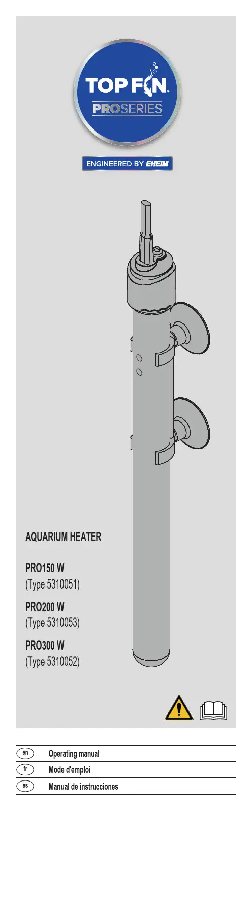
en Operating manualfr Mode d'emploies Manual de instrucciones‧FOR HOUSEHOLD USE ONLY ‧WARNING! RISK OF ELECTRIC SHOCK! ‧DO NOT RUN DRY!READ AND FOLLOW ALL SAFETY INSTRUCTIONS. ‧DANGER – To avoid possible electric shock, special care should be taken since water is employed in the use of aquarium equipment. For each of the following situations, do not attempt repairs by yourself. Return the appliance to an authorized service facility for service or discard the appliance.‧If the appliance shows any sign of abnormal water leakage, immediately unplug it from the power source.‧Carefully examine the appliance after installation. It should not be plugged in if there is water on parts not intended to be wet.‧Unplug the appliance from the socket outlet to disable any remotecommand.‧Do not operate any appliance if it has a damaged cord or plug, or if it is malfunctioning or has been dropped or damaged in any manner. ‧To avoid the possibility of the appliance plug or receptacle getting wet, position aquarium stand and tank to one side of a wall-mount-ed receptacle to prevent water from dripping onto the receptacle or plug. A ”drip loop”, shown in the figure, should be arranged by the user for each cord connecting an aquarium appliance to a receptacle. The ”drip loop” is that part of the cord below the level of the receptacle, or the connector if an extension cord is used, to prevent water traveling along the cord and coming in contact with the receptacle. If the plug or socket does get wet, DON’T unplug the cord. Disconnect the fuse or circuit breaker that supplies power to the appliance. Then unplug and examine for presence of water in the receptacle.‧Close supervision is necessary when any appliance is used by or near children. ‧To avoid injury, do not touch moving parts or hot parts such as heaters, reflectors, lamp bulbs, and the like. ‧Always unplug an appliance from an outlet when not in use, before putting on or taking off parts, and before cleaning. Never yank cord to pull plug from outlet. Grasp the plug and pull to disconnect. ‧Do not use an appliance for anything other than its intended use. The use of attachments not recommended or sold by the appli-ance manufacturer may cause an unsafe condition.‧Do not install or store the appliance where it will be exposed to the weather or to temperatures below freezing.‧Make sure an appliance mounted on a tank is securely in stalled before operating it.‧Read and observe all the important notices on the appliance.‧If an extension cord is necessary, a cord with a proper rating should be used. A cord rated for less amperes or watts than the appliance rating may overheat. Care should be taken to arrange the cord so that it will not be tripped over or pulled.‧This appliance has a polarized plug (one blade is wider than the other). As a safety feature, this plug will fit in a polarized outlet only one way. If the plug does not fit fully in the outlet, reverse the plug. If still does not fit, contact a qualified electrician. Never use with an extension cord unless plug can be fully inserted. Do not attempt to defeat this feature.‧Check that the voltage shown on the label of the unit corresponds to the voltage of the mains supply.‧Disconnect all electrical appliances from the mains before placing hands in the water.‧The line cord of this unit cannot be replaced or repaired. Should the line cord become damaged the appliance must be discarded.‧This device complies with part 15 of the FCC Rules. Operation is subject to the following two conditions:‧(1) This device may not cause harmful interference, and (2) this device must accept any interference received, including interfer-ence that may cause undesired operation.‧Any changes or modifications not expressly approved by the party responsible for compliance could void the user’s authority to operate the equipment.‧This equipment complies with FCC radiation exposure limits set forth for an uncontrolled environment. This equipment should be installed and operated with a minimum distance of 20 cm between the radiator and your body.NOTE:This equipment has been tested and found to comply with the limits for a Class B digital device, pursuant to Part 15 of the FCC Rules. These limits are designed to provide reasonable protection against harmful interference in a residential installation. This equipment generates, uses and can radiate radio frequency energy and, if not installed and used in accordance with the instructions, may cause harmful interfer-ence to radio communications. However, there is no guarantee that interference will not occur in a particular installation. If this equipment does cause harmful interference to radio or television reception, which can be determined by turning the equipment off and on, the user is encouraged to try to correct the interference by one or more of the following measures:‧Reorient or relocate the receiving antenna.‧Increase the separation between the equipment and receiver.‧Connect the equipment into an outlet on a circuit different from that to which the receiver is connected.‧Consult the dealer or an experienced radio/TV technician for help.Operating manualTOP FIN ®Pro Adjustable Aquarium HeaterGeneral User InstructionsFollow all operating manual instructions▶Before using the appliance for the first time, the operatingmanual must be read fully and understood.▶Consider the operating manual as part of the product and keep in a safe and accessible location.▶Enclose this operating manual if passing the appliance on toa third party.Symbol explanationThe following symbols are used on the appliance:The appliance must only be used indoors, and exclusively foraquariums.The appliance is of protection class II.The symbol indicates that the appliance is protected againstpermanent submerging.The following symbols and signal words are used in this operating manual:DANGER!Risk of serious personal injury or death from a general sourceof danger.DANGER!Danger of electric shock with the risk of serious personal injuryor death.WARNING!Danger of serious personal injury or health hazard.WARNING!Warning of hot surfaces with possible burns as a result.CAUTION!Note on the risk of material damage.Note with useful information and tips.Typographical conventions:Reference to a figure; in this case, reference to figure AYou are prompted for an action.ApplicationThe TOP FIN ®Pro heater is an adjustable heater for aquariums. The temperature range is 64 – 90°F ± 1°F or 18 – 32°C ±0.5°C.The appliance and all parts included in the scope of delivery are intended for private use and must only be used:‧For the heating of aquarium water in fresh and salt wateraquariums‧In compliance with the technical dataThe following limitations apply to the appliance:‧Do not use for commercial or industrial purposes‧Corrosive, highly flammable, aggressive or explosivesubstances, foodstuffs and drinking water must not be come into contact with the appliance‧Do not ever operate dry (without water)IP68⌦ASafety InstructionsRisks for persons and property can arise from this appliance if the appliance is improperly used or not used as intended or if the safety instructions are not heeded.‧Do not let the appliance packaging and small parts get into the hands of children as hazards can arise (danger of suffocation!). Keep away from animals!‧Before use, carry out a visual inspection to ensure that the appliance, especially the main cable and plug, are undamaged.‧Do not use the device if it does not function properly or if it is damaged.‧Never use the appliance with a damaged main cable.‧The connecting line of this device can not be replaced. When the line is damaged, the device must no longer be used.‧Repairs must only be carried out by an EHEIM service center.‧Do not carry the appliance by the main cable. To disconnect appliance, always pull on the plug and not the cable or appliance.‧Protect the main cable from heat, oil, and sharp edges.‧Only carry out the work described in these instructions.‧Never make technical modifications to the appliance.‧Only use original spare parts and accessories for the appliance.‧The device should be protected by means of a residual current protective device with a maximum rated residual current of 30 mA. Ask your electrician.‧If not in use, always disconnect all devices in the aquarium from the power supply before you install/remove any parts and before all cleaning and maintenance work.‧Protect the socket andplug against moisture. It is recommended to form a driploop with the cable to preventany water running along thecable to the socket.‧The electrical data of the appliance must match the data of the power source. This data is found on the type plate,the packaging, and in these instructions.‧Only connect the device to a power outlet. Current correctly installed with contact grounding. Unplug the device from socket outlet to disable remote command.‧Danger of burning! The appliance is very hot during and directly after operation. Never touch hot parts or the heating zone d! CommissioningInstalling the heater (⌦A)1. Remove the transportation protection e.2. Connect the suction device c to the suction device mount b.3. Connect the suction device mount to the heater (not in the areaof the heating zone d, the control light f and the indicatorLED g).4. Attach the appliance below water level on the inside of youraquarium (⌦B/C). Take care of the minimum water level.▶The heater must be rinsed well in order to guarantee consistentwater heating. Therefore, place the heater in an area with astrong flow.▶Only install the heater in a vertical position. OperationSystem requirementsWireless Connection (Wi-Fi) capable device (smart phone, tablet, desktop computer, etc.)Creating a network1. Plug in aquarium heater to begin operation. The Wi-Fi indicatorLED g light on the heater will light up.‧White flashing LED: Network is being sought or created.‧Blue LED: Network is connected and ready to start. Connecting to the WLAN network2. Open the network settings on your device (smart phone,tablet, etc.).3. Connect it to the WLAN network (SSID) that was just created byyour aquarium heater: EHEIM heater XXXXXXXX4. Enter the network security key.You find the SSID and the network security key on the mains cableor scan the QR-Code 1 for connection setup.Navigating to the Website5. Open your internet browser and go to http://192.168.1.1You can also use the QR code 2 to open the software in the browser.Start the configuration6. Select your desired language in the language selection fieldand proceed with the initial configuration. Follow the instructionsaccordingly.Control light f‧Lights up red: Heater is heating.‧Light off: Heater is not heating.LED indicator g‧Lights up white: Network is being sought or created.‧Lights up blue: Heater is in master mode.‧Lights up green: Heater is connected to another EHEIM digital device.Before you remove the heaterWARNING! Burning and fire hazards due to hot surfaces.▶Allow the appliance to cool down in the water for at least30 minutes before removing it.If you have accidentally removed the heater during operation:▶Do not submerge the heater back into the water.▶Do not touch any hot surfaces.▶Remove the main plug and allow the heater to cool down for at least one hour on a heat-resistant base.Thermal circuit breakerThe heater is equipped with a thermal circuit breaker as protection against overheating and any associated fire hazards. In the event of the heater being accidentally operated outside the water or when the water level is too low, it will be▶The appliance is not dishwasher-safe! Do not clean theappliance in the dishwasher.Cleaning1. Disconnect the heater from the power supply.2. Allow the appliance to cool down in the water for at least30 minutes.3. Take the appliance out of the aquarium.4. Clean the heater under running water.Shut offStorage1. Take the appliance out of the aquarium.2. Clean the appliance3. Store the appliance in a frost-proof place.Spare parts4 piece suction device (art. no. 7271100), suction device mount incl. 2 suction devices (art. no. 7443900)Wireless connectivity manual Contents1 Symbols (11)2 Initial configuration (12)3 Home page (18)4 Heater overview (20)5 Heater mode (22)5.1 Manual control (23)5.2 Smart control (24)6 Settings home (26)6.1 Connect with available network (29)6.2 E-mail adress for heater messages (31)6.3 Deactivating WLAN (32)6.4 Activating WLAN (33)7 Heater settings (34)8 Status LED indicator (37)9 Reset (39)10 Connecting with other TOP FIN®Pro device (39)11 Information (42)1 SymbolsHome pageSettingsRemoveChangeSaveAdd deviceOverviewManual controlSmart ControlTemperature/ Currentwater temperatureHeaterTimeTemperature setpointFactory DefaultsAttention2 Initial configuration1Select language.2Select unit system.3Change name of heater(optional).4Enter and save preferredname (optional).5Select next setting.6Add a new aquariumto network.7Change name (optional).8Select next setting.Continue with Step 12.Continue with Step 12.9Connecting with an existingaquarium (optional).10Selecting an aquarium fromthe list.11Connecting the aquarium.12Select heater regulationtypeMANUAL CONTROL.English.13Set the setpoint temperatureby moving the slider.14Save the settings.Continue with Step24.15Select heater regulationtypeSMART CONTROL.English.16Search for otherT OP FIN ®Pro devices.17Select your device.18Select your filter .19Pair with device .EHEIM Filter_XXXXXXXFilter XXXXXXX20To pair this filter it must beconfigured in Bio Mode.Filter XXXXXXX21Set the setpoint temperaturefor the day.Filter XXXXXXX22Set the temperaturedifference for night time.25Change name.for time23Save settings.Filter XXXXXXX24HOME PAGEOverview of aquarium with all connected devices.3 Home pageEnglish.26Enter and save preferredname.27Add a new aquarium.28Remove aquarium.29Add device.English30Change to view the heateroverview.2131Heater Overview: Thecurrent heater mode,temperaturesetpoint and current water temperature. 32Heater ON/OFF.4 Heater overview33Change the temperaturesetpoint.34Show the selection menu forOVERVIEW,TEMPERATURE andSETTINGS.35Go back to home page.5 Heater modeHOME PAGESelect the heater overview.Show the selection menu.Select TEMPERATUREfor heater modes.Overview of heater modes.40Select MANUALCONTROL.41Set the setpoint temperatureby moving the slider.42Save the settings.Select SMART CONTROL. Search for other T OP FIN®Pro devices.Select your device.EHEIM Filter_XXXXXXXSelect the network.English .47Pair with device .48To pair this filter it must be configured in Bio Mode.49Set the setpoint temperature for the day .50Set the temperaure difference for night time .Filter XXXXXXXFilter XXXXXXXFilter XXXXXXXfor time51Save settings.Filter XXXXXXX 52Select settings.53Call up network setting. Continue with 6.1.6 Settings home54Select/change language.55Enter the e-mail addressand user name to receivemessages from the heater.Continue with 6.2.56The current time is set.57Manual setting of dateand time.English.58Activate/deactivateautomatic change betweensummer and winter time.59Display network informationand switching off the WiFifunction.60Reset to factory settings.61Carry out manual update.6.1 Connect with available network62Search for availablenetworks.63Connect available network.64Enter password for theselected network.65Select CONNECT to connect to the network.66Change EHEIM h eaterXXXXXXXX network name to your own name.67Activate password usage and use a password with a minimum of 8 characters.68Save network settings.EHEIM h eater XXXXXXXXEHEIM heater XXXXXXXX#x1y2z3#69Go back to settings.70Enter the e-mail address and user name to receive messages from the heater.Only possible in networks with Internet connection.71Read and confirm the privacy policy.Name6.2 E-mail adress for heater messages72Save the data.Name73Select “Show NetworkInformation”.74Select “Turn off WiFi Feature”.6.3 Deactivating WLANFeature”.75Select “Deactivate WiFi” to disable the WiFi function.76Select “Deactivate WiFi” to disable the WiFi function.The status LED light on the heater flashes continuously yellow after approx. 3- 5 seconds. WiFi functiondeactivated. Device settings remainavailable.77Press the red reset buttonfor approx. 3–5seconds until the status LED lights up green.78The status LED flasheswhite. Network is being created. This process may take a few seconds.6.4 Activating WLANtake a few seconds.79If the status LED lights blue,a network has been created and is visible on a WLAN-enabled device (smart phone, tablet, etc.).80Change to the heateroverview.81Show the selection menu for OVERVIEW,TEMPERATURE and SETTINGS.82Select settings7 Heater settings83Enter and save preferredname (see items 3 & 4).84Open heater expert settings.85Adjustment of actualtemperature with externalthermometer. Example:Actual temperature = 79°FDisplay thermometer = 77°FSetting calibrate temperature=-2°F89Reset to factory settings. =-2°F86Select ”Show NetworkInformation“.87Change name.88Initial configuration reset.90LED flashes white:Device control unit is starting.91LED lights permanently blue:Device is ready foroperation (MASTER) and can be connected to WLAN-capable device (smart phone, tablet, etc.).92LED lights permanentlygreen:The device is ready for operation and is connected to a MASTER device.93LED flashes yellow: Firmware update in progress .94LED flashes green/yellow:Control unit waits until all connected control units are updated.8 Status LED indicator95LED lights permanently red:Website is missing and must be called up again via http://192.168.1.1/update.http://192.168.1.1/update.96LED flashes red/green/blue:Resetting the network settings or resetting to factory settings.97LED lights alternating white/red/white:Connection to home network or to MASTER network failed (network name wrong, password wrong, poor WLAN reception).98LED lights alternatinggreen/red/white:Master network or home network is no longer accessible. Control unit is restarting .99LED flashes pink:Detection mode is activated.100LED lights yellow:WLAN function isdeactivated. Reactivation (see items 77 -79).101Press the red reset buttonfor approx. 5 –8seconds.102LED flashes red/green/blue. Device is reset.103LED flashes white:Device control unitrestarting.104LED lights permanentlyblue:Device is ready for operation again.9 Reset105Add device.10 Connecting with other TOP FIN ®Pro deviceAdd device.106Select your device.107Select the network .108The selected device can be identified using DETECT. LED flashes pink.109The device can be added to the selected network using ADD. LED flashes white.EHEIM Filter XXXXXXX110If theLED lightspermanently green, complete the process with SAVE.111Devices are connected toeach other.11 InformationTOP FIN®Pro SeriesEngineered by EHEIMIf you are not satisfied with this product, return it with your valid proof of purchase for a refund. Conditions apply. See store or for details.For more information about Top Fin® products, please call 1-888-839-9638.Dist. by/par:Pacific Coast Distributing, Inc.19601 N. 27th Ave.Phoenix, AZ USA 85027Reproduction or copying – even parts thereof – only with the express permission of the producer.Les reproductions, copies et utilisations de nos logos et matériels et produits dérivés sont interdits à l’exploitation, de toute nature, et sont soumises au préalable, par écrit, au consentement et à l’approbation du fabricant.La reproducción o copia -incluso parcial- sólo puede hacerse con la autorización expresa del productor.© TOP FIN Pro SeriesEngineerd by EHEIM, Germany73 75 420 / 06.21 / C&F TOP FIN ®Pro SeriesEngineered by EHEIMIf you are not satisfied with thisproduct, return it with your validproof of purchase for a refund.Conditions apply.See store or fordetails.For more information aboutTOP FIN ® products,please call 1-888-839-9638.Dist. by/par:Pacific Coast Distributing, Inc.19601 N. 27th Ave.Phoenix, AZ USA 85027Made in GermanyTF-20-766150 IM。
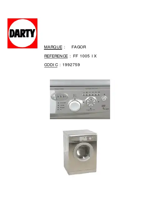
MARQUE : FAGOR REFERENCE : FF 1005 IX CODIC :1992759a/c bFrançais abcFrançaisrégler laafin de pou-Dévissez les vis des charnières et, avec un déplacementlatéral, démonter la porte de la machine à laver.Retirer le cadre de protection inférieur en dévissant les vis et retirer le panne-au fourni avec la machine à laver.La partie inférieure de la porte et le cadre de protection inférieur sont divi-sés en 7 sections de 10 mm. Sectionner, selon vos besoins et adapter le panneau décoratif aux nou-velles dimensions. Placer à nouveau le panneau décoratif et le cadre de pro-tection inférieur etremonter la porte.c7changer le Dévisser les vis des charnières et, avec un déplacementlatéral, démonter la porte de la machine à laver.Retirer le cadre de protection inférieur en dévissant les vis. Extraire le panneau fourni avec la machine à laver, ainsi que la plaque interne, en dévis-sant les vis la fixant. Extraire les charniè-res pour les placer sur le côté opposéà celui de la porte. Libérer le couvercle de protection de la porte pour le placer à l’endroit opposéoù se trouvaient les charnières.Monter à nouveau la plaque, le panne-au de la porte et le cadre de protection inférieur, afin de monter ultérieure-ment la porte. Extraire l’ancrage de fermeture situésur la face avant du meuble de la machine à laver, en dévissant la vis le fixant, et le placer où se trouvait aupa-ravant la charnière supérieure.Retirer également le couvercle de pro-tection et le placer où se trouvait aupa-ravant la charnièreinférieure.fgi Placer la porte eninsérant les charniè-res avec un légerdéplacement latéral,à son nouvel empla-cement. Serrer lesvis.Français a b9FrançaisDans cette machine,vous pouvez égale-ment employer des lessives liquides en utilisant pour cela la cuvette optionnelle qui peut être acquise àtravers le Réseaud’Assistance Technique La cuvette optionnelle doit être placée dans le compartiment de lava-ge.Souvenez-vous que la dose de lessive à utili-ser dépend toujours de:G La quantité de lingeà laver.G La saleté du linge.G La dureté de l’eau(Les informations concernant la dure-té de l’eau peuvent être sollicitéesauprès des organis-mes locaux compé-tents).Pensez qu’il existe des lessives concentréesquisont plus respectueuses de la nature et de l’environ-nement.L’utilisation d’une quantité de lessive plus grande que REMARQUE ÉCOLOGIQUEFrançaisREMARQUE ÉCOLOGIQUENous vous recommandons de choisir le programmeadapté à votre lavage,afin d’éviter le prélavageàchaque fois que cela est possible. Vous ferez des éco-nomies et vous contribuerez à une meilleure conserva-tion de l’environnement.Manuel d’installation et d’utilisation de l’appareil Manual de intalação e utilização do aparelho User installation and operation manualManual de instalación y uso del aparato TURBO TIMETURBO TIME PLUSFrançaisTouche: Rinçage extraAugmente le degré de rinçage final obtenu sur le linge; indiqué pour les grandes charges ainsi que pour les vête-ments des personnes àla peau sensible.Cela augmente la con-sommation en eau!Touche: LavageintensifCette option, spéciale-ment recommandée pourlinge très sale et taché,permet de meilleursrésultats grâce à l’allon-gement du cycle normalde lavage.Touche:Repassage facileCette option évite queles vêtements ne soientfroissés grâce à la réali-sation d’un programmespécial pendant lequel ily a plusieurs tours spé-ciaux permettant dedéfroisser les vête-ments après l’essoragener l’horaire différésouhaité, appuyer sur la touche Horloge jus-qu’à afficher l’heure dif-férée souhaitée.Sélection de l’heure différéeModèle à visuelSélection de l’heure différéeFrançaisSélection du blo-cageFonction du blocage Le blocage permet d’assurer que les manipulations des dif-férentes touches ne vont pas affecter le programme ni les options de lavagesélectionnées. Il est utilisé afin d’éviter les manipulations de la part des enfants, etc. Actionner le blocage Pour activer le verrouillage, mainte-nir enfoncée la tou-che Marche.Après ces quelques secondes, le signal lumineux de la touchede marche clignotera, ce qui confirme que le blocage est habilité, et la machine à laver se mettra en marche.Le blocage doit être activé après la sélec-tion du programme de lavage et de toutes les options de ce dernier, ainsi que la program-mation différée souhai-tée.Désactiver le blo-cageLe blocage est éliminé àla fin du programme delavage, lorsque le signallumineux de FIN s’allume.Pour annuler le verrouilla-ge avant la fin du cyclede lavage, maintenirenfoncée la touche à nou-veau pendant au moins 3secondes.Les 3 secondes écoulées,le voyant s’éteindra et lelave-linge se mettra enPause. La touche OFFn’élimine pas le verroui-llage (enfoncer la toucheou l’interrupteur central dumodèle intégrable total).Lorsqu’on remet en mar-che la machine à laver,elle continuera l’exécutiondu programme au pointoù il s’était arrêté.FrançaisPrélavageLavageRinçageREMARQUE ÉCOLOGIQUEAfin de préserver l’environnement,votre machine àlaver est équipée d’un système qui a la capacité de s’adapter aux différentes conditions d’utilisation(charge de linge et nature du tissu) en garantissantLAVE-LINGEFrançaisDans le cas où vous détecteriez un problème lors de l’utilisation de votre machine à laver, il est probable que vous puissiez le résoudre après avoir consulté les indications suivantes. Si ce n’était pas le cas,débranchez l’appareil et contactez le SERVICE D’ASISSTANCE TECH-NIQUE TECNICA.• Pourquoi la machine à laver ne se met pas en marche?Les causes peuvent être les suivantes:–Il n’y a pas de tension sur le réseau électrique.–Les fusibles de l’installation électrique peuvent avoir “sautés”.–La machine à laver n’est pas connectée à l’alimentation.–Vous n’avez pas appuyé sur la touche Marche/Arrêt (l’indicateur lumineux de cette touche doit être alluméen continu).–La commande de sélection n’a pas été tirée vers l’extérieur.–La porte de la machine à laver est mal fermée.Lorsque les indicateurs de prélavage et de fin cligno-tent ou lorsque apparaît F04 sur l’écran de votremachine à laver. Il faut ensuite vérifier la porte et bien la fermer.• Pourquoi la machine à laver vibre-t-elle ou fait-elle un bruit excessif?Les causes peuvent être les suivantes:–Les vis de fixation interne n’ont pas été retirées.–La machine à laver n’est pas bien mise à niveau.LAVE-LINGE• Pourquoi la machine à laver ne se remplit-elle pas d’eau?–Lorsque cette anomalie est détectée, les indicateurs de Lavage et de Rinçage se mettent à clignoter en alternance ou, si votre machine à laver dispose d’un écran, celui-ci indiquera F01.–L’anomalie d’entrée d’eau peut être due à une coupure d’eau, à un robinet d’entrée d’arrivée d’eau à la machi-ne à laver fermé ou à un filtre d’arrivée d’eau à la machine à laver obstrué.–Par conséquent, les attitudes possibles sont: attendre la fin de la coupure d’eau, ouvrir le robinet d’arrivée d’eau, et enlever le tuyau flexible d’arrivée d’eau et en nettoyer le filtre.•Pourquoi la machine à laver ne procède ni à l’écoulement de l’eau ni àl’essorage ?–Lorsque cette anomalie est détectée, les indicateurs de rinçage et de Fin se mettent à clignoter ou bien,apparaît le message F02 si votre machine à laver dis-pose d’un écran.–Les raisons de cette anomalie peuvent être: obstruc-tion de la pompe à moteur d’écoulement de la machi-ne à laver, obstruction dans les tuyauteries d’écoule-ment de l’immeuble ou, une mauvaise connexion élec-trique de la pompe à moteur.–Action: si la raison correspond à l’obstruction de lapompe à moteur, y accéder comme cela est indiqué dans le paragraphe 2, Entretien et nettoyage de l’appareil.• Pourquoi la machine à laver ne procède-t-elle pas à l’essorage?–Lorsque cette anomalie est détectée, les indicateurs de Prélavage et de Lavage se mettent à clignoter ou,le message F03 apparaît si votre machine à laver dis-pose d’un écran.–Cette anomalie est due au fait que la distribution du linge dans le tambour est très inégale et qu’il peut entraîner un niveau excessif de vibrations.–Le mode d’action est de remettre la machine à laver au point d’essorage.•Est-il plus efficace de mettre la lessive dans la cuvette ou directement dans le tambour?L’utilisation des “ tablettes ” qui se placent directement dans le tambour est de plus en plus fréquent. Ces tablet-tes garantissent un bon lavage et n’abîment pas le linge.Cependant, d’autres produits de lessive en poudre ou liquides contiennent des composants agressifs qui, avec un contact direct, peuvent abîmer le linge.Dans ces situa-tions, il est recommandé d’utiliser la cuvette.Para estas situaciones es recomendable utilizar la cubeta.25FrançaisCela peut être dû au fait que la machine à laver est équi-pée d’un système qui a la capacité de s’adapter à la char-ge de linge et à la nature du tissu, en ajustant le niveaud’eau et d’énergie utilisé, afin de préserver l’environne-ment. Par conséquent, même si la quantité d’eau que vouspouvez observer par le hublot vous semble faible, ne vousen faites pas, le degré d’efficacité du lavage et du rinçagesera optimum.• Pourquoi de l’eau sort-elle par la cuvette?Cela peut être dû au fait que la cuvette ou le comparti-ment de distribution ait besoin d’être nettoyé. Cette opéra-tion simple est décrite dans la partie Entretien et nettoya-ge de l’appareil.1- Nettoyage de la cuvette de lessive.•Pourquoi m’est-il impossible d’ouvrir le hublot immédiatement après la fin du lavage?Les machines à laver actuelles sont équipées de systèmesde sécurité pour les utilisateurs. L’un d’entre eux consisteà ne pas permettre l’ouverture de la machine à laver sansgarantir que le tambour est totalement arrêté. Voilà pour-quoi il faut attendre 2 minutes pour ouvrir le hublot.• Autres anomalies–La machine à laver a la possibilité de détecter d’autresanomalies. Lorsque cela arrive, tous les indicateursdes phases de lavage se mettent à clignoter ou, appa-raîtront sur l’écran divers messages d’erreurs F05,F06, ….., F10.–Ces anomalies peuvent être dues à des causes trèsdiverses.–Dans ce cas, il faut appeler le SERVICE TECHNIQUEOFFICIELLAVE-LINGEREMARQUE ÉCOLOGIQUEAfin de préserver l’environnement, remettez votre machine à laver usagée dans。
Ranger 305 D (CE)OPERATOR’S MANUALIM837-AJune, 2005Safety Depends on YouLincoln ar c welding and cutting equipment is designed and built with safety in mind. However, your overall safety can be increased by proper installation ... and thought-ful oper ation on your par t.DO NOT INSTALL, OPERATE OR REPAIR THIS EQUIPMENT WITHOUT READING THIS MANUAL AND THE SAFETY PRECAUTIONS CONTAINED THROUGHOUT.And, most impor tantly, think befor e you act and be careful.EN 60974-1Copyright © 2005 Lincoln Global Inc.Mar ‘95Mar ‘95Mar. ‘93c/o Balmes, 89 - 80 2a 08008 Barcelona SPAINMeasured sound power level:LWA 98 dB (net power Pel = 7.5kW) LWA 96 dB (net power Pel = 7.5k W)26 April 2005Dario Gatti,ixixfor selecting a QUALITY product by Lincoln Electric. We want you to take pride in operating this Lincoln Electric Company product ••• as much pride as we have in bringing this product to you!Page Installation.......................................................................................................................Section A Technical Specifications.......................................................................................................A-1 Safety Precautions........................................................................................................A-2Location and Ventilation................................................................................................A-2Stacking........................................................................................................................A-2Angle of Operation........................................................................................................A-2Lifting.............................................................................................................................A-2High Altitude Operation.................................................................................................A-2High Temperature Operation........................................................................................A-2Cold Weather Operation...............................................................................................A-2Towing...........................................................................................................................A-3Vehicle Mounting...........................................................................................................A-3 Pre-Operation Engine Service..............................................................................................A-3 Oil..................................................................................................................................A-3Fuel...............................................................................................................................A-3Engine Coolant..............................................................................................................A-4Battery Connections......................................................................................................A-4Muffler Outlet Pipe........................................................................................................A-4Spark Arrester...............................................................................................................A-4Remote Control.............................................................................................................A-4 Electrical Connections..........................................................................................................A-4 Machine Grounding.......................................................................................................A-4Welding Terminals........................................................................................................A-5Welding Output Cables.................................................................................................A-5Cable Installation...........................................................................................................A-5 Auxiliary Power ....................................................................................................................A-5 Standby Power Connections................................................................................................A-5 Connection of Lincoln Electric Wire Feeders................................................................A-6,A-7 ________________________________________________________________________________ Operation.........................................................................................................................Section B Safety Precautions ..............................................................................................................B-1 General Description..............................................................................................................B-1 For Auxiliary Power..............................................................................................................B-1 Engine Operation..................................................................................................................B-1 Break in Period.....................................................................................................................B-1 Add Fuel...............................................................................................................................B-1 Fuel ......................................................................................................................................B-1 Welder Controls............................................................................................................B-2Engine Controls.............................................................................................................B-3Starting and Stopping the Engine...........................................................................B-3, B4Stopping .......................................................................................................................B-4 Welding Operation................................................................................................................B-5 Duty Cycle.....................................................................................................................B-5Constant Current (Stick) Welding..................................................................................B-5Downhill Pipe (Stick) Welding.......................................................................................B-5Tig Welding...................................................................................................................B-5Typical Current Ranges for Tungsten Electrodes.........................................................B-5Wire Welding-CV...........................................................................................................B-6Arc Gouging..................................................................................................................B-6Auxiliary Power.............................................................................................................B-6 ________________________________________________________________________________ Accessories.....................................................................................................Section C Field Installed Options / Accessories ...............................................................................C-1 ________________________________________________________________________________Check with distributor for the recommended trailer for use with this equipment for road, in-plant and yard towing by a vehicle. If the user adapts a non-Lincoln trailer, he must assume responsi-bility that the method of attachment and usage does not result in a safety hazard nor damage the welding equipment. Some of the factors to be considered are as follows:1. Design capacity of trailer vs. weight of Lincoln equipment and likely additional attachments.2.Proper support of, and attachment to, the base of the weld-ing equipment so there will be no undue stress to the frame-work.3.Proper placement of the equipment on the trailer to insurestability side to side and front to back when being moved and when standing by itself while being operated or ser-viced.4. Typical conditions of use, i.e., travel speed; roughness of sur-face on which the trailer will be operated; environmental con-ditions; like maintenance.5. Conformance with laws in nation / region to be used.• The installation complies with the National Electrical Code and all other applicable electri-cal codes.•The premises is isolated and no feedback into the utility system can occur. Certain laws require the premises to be isolated before the generator is linked to the premises. Check your local requirements.-----------------------------------------------------------------------CONNECTION OF LINCOLN ELECTRIC WIRE FEEDERSConnection of LN-15 to the Ranger 305DThese connections instructions apply to both the LN-15 Across The-Arc and Control Cable models. The LN-15 has an internal contactor and the electrode is not energized until the gun trigger is closed. When the gun trigger is closed the wire will begin to feed and the welding process is started.• Shut the welder off.• For electrode Positive, connect the electrode cable to the "+" terminal of the welder and work cable to the "-" terminal of the welder. For electrode Negative, connect the electrode cable "-" terminal of the welder and work cable to the "+" terminal of the welder.• Across The-Arc Model:Attach the single lead from the front of the LN-15 to work using the spring clip at the end of the lead. This is a control lead to supply current to the wire feeder motor; it does not carry welding current.Set the "WELD TERMINALS" switch to "WELD TER-MINALS ON".• Control Cable Model:Connect Control Cable between Engine Welder and Feeder.Set the MODE switch to the "CV-WIRE " position. Set the "WELD TERMINALS" switch to "REMOTELY CONTROLLED".Set the "WIRE FEEDER VOLTMETER" switch to either "+" or "-" as required by the electrode polarity being used.Set the "ARC CONTROL" knob to "0" initially and adjust to suit.Set the "IDLE" switch to the "AUTO" position. 0AUXILIARY POWER:Start the engine and set the IDLER control switch tothe desired operating mode. Full power is availableregardless of the welding control settings providing no welding current is being drawn.Simultaneous Welding and Auxiliary Power Loads While welding, the amount of 3-phase Auxiliary power available is reduced.(See table A.4)When in the TOUCH START TIG mode and when a Amptrol is connected to the 6-pin Connector the OUT-PUT dial is used to set the maximum current range of the CURRENT CONTROL of the Amptrol.The ARC CONTROL is not active in the TIG mode.The RANGER 305D (CE) can be used in a wide variety of DC TIG welding applications. In general the ‘Touch Start’ feature allows contamination free starting without the use of a Hi-frequency unit. If desired, the K930-2TIG Module can be used with the RANGER 305D (CE).The settings are for reference.RANGER 305D (CE) settings when using the K930-2TIG Module with an Amptrol or Arc Start Switch:• Set the MODE Switch to the TOUCH START TIG setting.• Set the "IDLER" Switch to the "AUTO" position.• Set the "WELDING TERMINALS" switch to the"REMOTELY CONTROLLED" position. This will keepthe "Solid State" contactor open and provide a “cold”electrode until the Amptrol or Arc Start Switch ispressedWhen using the TIG Module,the OUTPUT control on the RANGER 305D (CE) is used to set the maximumrange of the CURRENT CONTROL on the TIG module or an Amptrol if connected to the TIG Module. (See Table B.2.)WIRE WELDING-CV Connect a wire feeder to the Ranger 305D according to the instructions in INSTALLATION INSTRUCTIONS Section.The RANGER 305D (CE) in the CV-WIRE mode, per-mits it to be used with a broad range of flux cored wire (Innershield and Outershield) electrodes and solid wires for MIG welding (gas metal arc welding). Welding can be finely tuned using the ARC CONTROL. Turning the ARC CONTROL clockwise from –10 (soft) to +10 (crisp)changes the arc from soft and washed-in to crisp and narrow. It acts as an inductance/pinch control. The proper setting depends on the procedure and operator preference. Start with the dial set at 0.TABLE A.4FIELD INSTALLED OPTIONS / ACCESSORIESK1898-1 SPARK ARRESTOR- Mounts between muf-fler & elbow to eliminate any risk of spark from exhaust. K704 ACCESSORY SET- Includes (10m) 35 ft. of electrode cable and (9.m) 30 ft. of work cable, head-shield, work clamp electrode holder. Cables are rated at 400 amps, 100% duty cycle.K857(7.6m) 25 ft. or K857-1(30.4m) 100 ft. REMOTE CONTROL - Portable control provides same dial range as the output control on the welder. Has a convenient 6 pin plug for easy connection to the welder.ENGINE OIL CHANGEDrain the engine oil while the engine is warm to assure rapid and complete draining. It is recommend-ed that each time the oil is changed the oil filter be changed as well.• Be sure the unit is off. Disconnect the negative bat-tery cable to ensure safety.• Locate oil drain hose and valve in bottom of base and pull through the hole in the battery access panel on the welder.• Remove the cap from the drain valve. Push valve in and twist counterclockwise. Pull to open and drain the oil into a suitable container for disposal.• Close the drain valve by pushing in and twisting clockwise. Replace the cap.• Re-fill the crankcase to the upper limit mark on the dipstick with the recommended oil (see engine oper-ation manual OR engine service items decal OR below). Replace and tighten the oil filler cap secure-ly.• Push oil drain hose and valve back into unit, re-con-nect negative battery cable, and close doors and engine top cover before restarting unit.Wash your hands with soap and water after handling used motor oil. Please dispose of used motor oil in a manner that is compatible with the environment. We suggest you take it in a sealed container to your local service station or recycling center for reclama-tion. DO NOT throw it in the trash; pour it on the ground or down a drain.ENGINE OIL REFILL CAPACITIESWithout oil filter replacement:• 3.2 liter (3.3 U.S. Quart)With oil filter replacement:• 3.2 liter ( 3.4 U.S. Quart.)Use motor oil designed for diesel engines that meets requirements for API service classification CC/CD/CE/CF/CF-4/CG-4 or CH-4.ACEA E1/E2/E3. Always check the API service label on the oil container to be sure it includes the letters indicated. (Note: An S-grade oil must not be used in a diesel engine or damage may result. It IS permissible to use an oil that meets S and C grade service classifi-cations.)SAE 10W30 is recommended for general, all tempera-ture use, -15C to 40C (5F to 104F).See engine owner’s manual for more specific informa-tion on oil viscosity recommendations.removal/installation. Most latchesare spring loaded to fold back when open. The filter fits tightly over the outlet tube, creating the critical seal on the inside diameter of the filter endcap. The filter should be removed gently to reduce the amount of dust dislodged. There will be some initial resistance, similar to breakingClean Sealing Surface 3of the Outlet Tube Use a clean cloth to wipe the sealing surface. Dust on the outside diameter of theoutlet tube could hindernew filter is inserted.Insert the New7RadialSealô Filter by HandInsert carefully. Seat the new filter by hand, making certain it is completely into the air cleaner housing before latching the cover in place. If the cover hits the filter before it is fully in place, remove the cover and push (by hand) thefilter further intothe air cleanerwith no extra force.Never use the latches on the cover to force the filter into the air cleaner! It is tempting to assume the cover will do the job of seating the filter ñ but it will not! Using the latches to push the filter in could cause damage to the housing and will void theClean the Inside of 4the Outlet Tube Carefully wipe the insideof the outlet tubewith a clean cloth.Dirt accidentlytransferred to theinside of the outlettube will reach theengine and cause wear.(Engine manufacturers says that it takes only a few grams of dirt to ëdustí an engine!) Be careful not to damage the sealing area on the tube.of leaks. A streak of dust onthe clean side of the filterInspect the NewFilter for DamageInspect the new filter carefully,paying attention to the inside ofthe open end,which is thesealing area.NEVER installa damaged filter.This Troubleshooting Guide is provided to help you locate and repair possible machine malfunctions.Simply follow the three-step procedure listed below.Step 1.LOCATE PROBLEM (SYMPTOM).Look under the column labeled “PROBLEM (SYMP-TOMS)”. This column describes possible symptoms that the machine may exhibit. Find the listing that best describes the symptom that the machine isexhibiting.Step 2.POSSIBLE CAUSE.The second column labeled “POSSIBLE CAUSE ” lists the obvious external possibilities that may contribute to the machine symptom.Step 3.RECOMMENDED COURSE OF ACTIONThis column provides a course of action for the Possible Cause, generally it states to contact your local Lincoln Authorized Field Service Facility.If you do not understand or are unable to perform the Recommended Course of Action safely, contact your local Lincoln Authorized Field Service Facility.HOW TO USE TROUBLESHOOTING GUIDEService and Repair should only be performed by Lincoln Electric Factory Trained Personnel.Unauthorized repairs performed on this equipment may result in danger to the technician and machine operator and will invalidate your factory warranty. For your safety and to avoid Electrical Shock, please observe all safety notes and precautions detailed throughout this manual.__________________________________________________________________________。
B-VENT FREESTANDING FIREPLACE HEATEROWNER’S OPERATION AND INSTALLATION MANUAL®MSBVBN, MSBVBP REMOTE READYSave this manual for future reference.FOR YOUR SAFETYWHAT TO DO IF YOU SMELL GAS •Do not try to light any appliance.•Do not touch any electrical switch•Do not use any phone in your building.•Immediately call your gas supplier from a neighbor’s phone. Follow the gas supplier’s instructions.•If you cannot reach your gas supplier, call the fire department.WARNING: Improper instal-lation, adjustment, altera-tion, service, or maintenance can cause injury or property damage. Refer to this manual for correct installation and operational procedures. For assistance or additional in-formation consult a quali-fied installer, service agency, or the gas supplier.This appliance may be installed in an aftermarket* manufactured (mobile) home, where not prohibited by state or local codes.* Aftermarket: Completion of sale, not for purpose of resale, from the manufacturerWARNING: If the information in this manual is not followed exactly, a fire or explosion may result causing property damage, personal injury, or loss of life.FOR YOUR SAFETYDo not store or use gasoline or other flammable vapors and liquids in the vicinity of this or any other appliance.—Installation and service must be performed by a qualified installer, service agency, or the gas supplier.IMPORTANT: This fireplace must be installed into approved Sun Valley cast iron stove bodies,models MC(*) series ONLY. See page 3 of this manual. *Indicates color suffix designation.TM2B-VENT FREESTANDING FIREPLACE106022SUN VALLEY STOVE COMPANYOWNER’S MANUAL31060224B-VENT FREESTANDING FIREPLACE106022SUN VALLEY STOVE COMPANYOWNER’S MANUAL51060226B-VENT FREESTANDING FIREPLACE106022SUN VALLEY STOVE COMPANYOWNER’S MANUAL71060228B-VENT FREESTANDING FIREPLACE106022SUN VALLEY STOVE COMPANYOWNER’S MANUAL910602210B-VENT FREESTANDING FIREPLACE106022SUN VALLEY STOVE COMPANYVENTING INSTALLATION ContinuedHIGH ALTITUDE INSTALLATIONYour Sun Valley B-vent freestanding fire-place heater has been AGA tested and ap-proved for elevations from 0-2000 feet and CGA certified for elevations from 0-4500 feet. When installing this fireplace at an eleva-tion above 2000 feet (in the USA), you may need to decrease the input rating by chang-ing the existing burner orifice to a smaller size. Reduce input 4% for each 1000 feet above sea level. Check with your local gas company for proper orifice size identifica-tion and proper orifice for your location. When installing this fireplace at an eleva-tion above 4500 feet (in Canada), check with local authorities.For assistance with any high altitude installa-tion contact DESA International’s Technical Service Department at 1-800-DESA-LOG (1-800-337-2564).TROUBLESHOOTINGVENTINGPROBLEMSMost venting problems are caused by incor-rect vent sizing, improper installation, orinadequate air supply. A preliminary checkfor a field problem might include:•Using a draft meter to determine ifventing system draft meetsmanufacturer’s specifications•Checking the vent sizing according tomanufacturer’s specifications, applianceinput, and venting configuration•Examining the entire venting system forfaults such as disconnected joints fordamaged vent sections•Making sure vent and air openings arenot obstructedIf these procedures do not reveal the source ofthe problem, troubleshooting may includeattention to common venting problems.FLUE GAS SPILLAGESpillage occurs when flue gases cannot exitthe vent system and back up into the dwell-ing. A primary symptom of appliancesequipped with a Vent Safety Shutoff System(flue spill switch) is unexplained applianceshutoffs. Other symptoms of flue gas spillageat the draft hood include condensation onwalls and windows and/or noticeable odors.Spillage may also result in the release ofcarbon monoxide, a colorless, odorless, highlytoxic gas. A simple spillage test can be con-ducted if spillage is suspected. See CheckingGas Connection, pages 13 and 14.CAUSES OF SPILLAGE ANDCORRECTIVE ACTIONIncorrect Vent SizingIf the vent is too small or too short, spillagemay occur. If the vent is too large, excessivedilution air may cool flue gases and reducedraft, causing spillage. The vent cap sizeshould also be checked. Checkmanufacturer’s instructions, appliance in-put rating, and appropriate sizing tables.Venting ConditionLoose joints can affect draft and cause spill-age. “Mashed” vent sections and damagedvent caps can restrict flow and cause spill-age. Examine and replace as needed.ObstructionsSmall animals or birds may get into and blockthe vent or draft hood outlet. Dust, lint, andforeign objects may obstruct air inlets. Re-move obstructions and clean openings.Lateral RunLengthy horizontal or non-vertical runs causeresistance to flow and may reduce draftenough to cause spillage. The pitch of lateralruns can also be a problem; lateral runsshould be pitched 1/4" rise per foot of hori-zontal run from the appliance to the vent.ElbowsToo many elbows cause excessive restric-tion of flow and may result in spillage.Usually, two 90º turns can be tolerated in aproperly sized venting system. More thantwo may cause problems and necessitatechanging the system.Negative Pressure in theDwellingAn extremely tight house may not supplyadequate combustion and venting air. Useof mechanical exhaust such as a dryer ventor range vent may worsen the problem. Anair exchange system must be installed in thedwelling to correct this problem.Flue Gas CoolingVenting exposed to extremely cold tem-peratures or venting of single wall construc-tion loses heat needed to maintain draft;massive masonry chimneys absorb neededheat. If the flue gases cool excessively, draftis reduced and spillage may result. Useproper materials, insulate and protect prop-erly, reline when necessary.Down DraftsIn certain wind conditions and in certainrelationships with nearby structures andobjects, high pressure conditions may affectdraft negatively. Relocate the vent cap, raiseits height, or use an approved high wind cap.1110602212B-VENT FREESTANDING FIREPLACE1060221310602214B-VENT FREESTANDING FIREPLACE10602215106022161060221710602218B-VENT FREESTANDING FIREPLACE10602220B-VENT FREESTANDING FIREPLACE1060222110602222B-VENT FREESTANDING FIREPLACE106022OBSERVED PROBLEMBurner does not light after pilot is lit Delayed ignition burnerBurner backfiring during combustionSlight smoke or odor during initial operation Heater produces a whistling noise when burner is litGlass sootsFireplace produces a clicking/ticking noise just after burners are lit or shut off Remote does not function REMEDY1.Clean burner (see Cleaning andMaintenance, page 21) or replace burner orifice2.Contact local propane/LP or natural gascompany3.Reconnect leads (see Wiring Diagram,page 25)4.Replace thermopile1.Contact local propane/LP or natural gascompany2.Clean burner (see Cleaning and Main-tenance, page 21) or replace burner orifice 1.Clean burner (see Cleaning andMaintenance, page 21) or replace burner orifice2.Replace damaged burner3.Replace gas control1.Problem will stop after a few hours ofoperation1.Turn control knob to LO position andlet warm up for a minute2.Operate burner until air is removed fromline. Have gas line checked by local pro-pane/LP or natural gas company3.Clean burner (see Cleaning andMaintenance, page 21) or replace burner orifice1.Adjust the log set so that the flame doesnot excessively impinge on it2.Inspect the opening at the base of theburner to see that it is NOT packed with any type of material1.This is common. If noise is excessive,contact qualified service person1.Replace 9-volt batteries in receiver andremote controlTROUBLESHOOTINGContinuedPOSSIBLE CAUSE1.Burner orifice clogged2.Inlet gas pressure is too low3.Thermopile leads disconnected or im-properly connected4.Thermopile is defective1.Manifold pressure is too low2.Burner porting or orifice clogged1.Burner orifice is clogged or damaged2.Damaged burner3.Gas regulator defective1.Residues from manufacturing processesand logs curing1.Turning control knob to HI positionwhen burner is cold2.Air in gas line3.Dirty or partially clogged burner orifice1.Flame impingement on logs2.Debris around burner air mixer1.Metal expanding while heating or con-tracting while cooling1.Battery is not installed or battery poweris low Continued2310602224B-VENT FREESTANDING FIREPLACE1060222510602226B-VENT FREESTANDING FIREPLACE106022SPECIFICATIONSMSBVBN MSBVBP 21,000-30,000 Btu/h20,000-28,000 Btu/hGas Type Natural Propane/LP IgnitionPiezo Piezo Manifold Pressure3.5" w.c.10.0" w.c.Minimum Inlet Supply Pressure4.5" w.c.11.0" w.c.Thermal Efficiency70%70%Dimension, Inches/mm (HxWxD)Fireplace*28" x 27" x 23"28" x 27" x 23"711.2 x 685.8 x 584.2 mm711.2 x 685.8 x 584.2 mmCarton (Insert Only)23" x 33" x 23"23" x 33" x 23"584.2 x 838.2 x 584.2mm584.2 x 838.2 x 584.2mmWeight, lbs/kgFireplace 70 lbs/31.8 kg 70 lbs/31.8 kg Shipping75 lbs/34 kg75 lbs/34 kg* When installed in Sun Valley cast iron stove body (MC Series).2710602228B-VENT FREESTANDING FIREPLACE1060222910602230B-VENT FREESTANDING FIREPLACE106022OWNER’S MANUAL31106022LIMITED WARRANTYB-VENT FREESTANDING FIREPLACE AND SUN VALLEY STOVE CHASSISDESA International warrants this product to be free from defects in materials and components for four (4) years from the date of first purchase, provided that the product has been properly installed, operated and maintained in accordance with all applicable instructions.To make a claim under this warranty the Bill of Sale or cancelled check must be presented.This warranty is extended only to the original retail purchaser. This warranty covers the cost of part(s) required to restore this heater to proper operating condition and an allowance for labor when provided by a DESA Authorized Service Center. Warranty part(s) MUST be obtained through authorized dealers of this product and/or DESA International who will provide original factory replacement parts.Failure to use original factory replacement parts voids this warranty. The heater MUST be installed by a qualified installer in accordance with all local codes and instructions furnished with the unit.This warranty does not apply to parts that are not in original condition because of normal wear and tear, or parts that fail or become damaged as a result of misuse, accidents, lack of proper maintenance or defects caused by improper installation. Travel, diagnostic cost,labor, transportation and any and all such other costs related to repairing a defective heater will be the responsibility of the owner.TO THE FULL EXTENT ALLOWED BY THE LAW OF THE JURISDICTION THAT GOVERNS THE SALE OF THE PRODUCT;THIS EXPRESS WARRANTY EXCLUDES ANY AND ALL OTHER EXPRESSED WARRANTIES AND LIMITS THE DURA-TION OF ANY AND ALL IMPLIED WARRANTIES, INCLUDING WARRANTIES OF MERCHANTABILITY AND FITNESS FOR A PARTICULAR PURPOSE TO FOUR (4) YEARS ON ALL COMPONENTS FROM THE DATE OF FIRST PURCHASE;AND DESA INTERNATIONAL’S LIABILITY IS HEREBY LIMITED TO THE PURCHASE PRICE OF THE PRODUCT AND DESA INTERNATIONAL SHALL NOT BE LIABLE FOR ANY OTHER DAMAGES WHATSOEVER INCLUDING INDIRECT,INCIDENTAL OR CONSEQUENTIAL DAMAGES.Some states do not allow a limitation on how long an implied warranty lasts or an exclusion or limitation of incidental or consequential damages, so the above limitation on implied warranties, or exclusion or limitation on damages may not apply to you.This warranty gives you specific legal rights, and you may also have other rights that vary from state to state.For information about this warranty write:KEEP THIS WARRANTYWARRANTY INFORMATIONModel Serial No.Date PurchasedAlways specify model and serial numbers when communicating with the factory.We reserve the right to amend these specifications at any time without notice. The only warranty applicable is our standard written warranty. We make no other warranty, expressed or implied.106022-0155997Rev. A 08/99NOT A UPC2701 Industrial Drive P.O. Box 90004Bowling Green, KY INTERNATIONALSun Valley Stove CompanyDiv. MASDA Corporation Box DWhippany, NJ or106022 01。

Installation and operating manual ENCLOSURE HEATER TEF 9208 TUM7132 __________________________________________________________________________________Installlation ManualENCLOSURE HEATER TEF 9208Zone 1, Zone 2 & Safe AreaDocument properties (TUM7132)Revision Comment Revision date Approved- First issue - AKAA Minor changes 06.04.2022 CKRB Minor changes 07.04.2022 CKRC Minor changes 29.04.2022 CKRD Updated with new certificate and UKCA 01.04.2023 CKRInstallation and operating manualContentsDocument properties (TUM7132) (1)Warnings and risk levels (3)General information (3)Marking and intended use (4)Special conditions for safe use (5)Technical data (5)Product description (6)Transport and storage (6)Mounting and installation (7)Mounting (7)Electrical connections (8)Commissioning (9)Operation (9)Maintenance and cleaning (9)Disposal (10)Compliance/Conformity (10)R. Stahl Tranberg declaration of Conformity: (11)Warnings and risk levelsDANGERNon-compliance with the instruction results in risk of severe or fatal injuries to personsWARNINGNon-compliance with the instruction may result in risk of severe or fatal injuries to personsCAUTIONNon-compliance with the instruction may result in risk of injuries or damage to equipmentNOTICENon-compliance with the instruction may result in reduced lifetime of equipment, malfunctions etc.General informationBefore installation, make sure to read and understand this installation and operating manual.Observe national assembly and installation regulations.Always contact the manufacturer if anything is unclear, or if you notice any faults on the product or in this document.This installation and operating manual shall be available to anyone operating, installing, inspecting, modifying or repairing the equipment.For further information, see the referenced certificates.Marking and intended useDANGERNot for use in Zone 0 or Class I division 1. Shall be placed inside an enclosure with IP min. IP54CAUTIONThe enclosure heater shall not be exposed to direct sunlight, dust, water or similar. The enclosure heater should be protected from contamination and shall not be cleaned with running water.•CE•ATEX / IECEx/ UKEx: II 2G Ex 60079-30-1 IIC T4 GbI 2G Ex 60079-30-1 eb mb IIC T4 GbFor use in hazardous areas Zone 1 or Zone 2For use in onshore/offshore areas protected from exposure.Special conditions for safe useDANGERSpecial conditions for safe use are critical conditions to maintain the explosion protection of the equipment. These shall be adhered to in all cases and under all circumstances.•The heaters with permanently connected unterminated flying lead cable need an appropriate protection of the free end of the cable (for example terminated in an Ex e junction box).•The heaters with thermostat shall be connected to a circuit breaker with rated current max. 16A and a breaking capacity of min. 1500A.•The supply circuit shall include an electrical protection device in conformity with EN 60079-30-1 (For version 2015/2017 clause 4.3).•Enclosure heaters of type TEF 9208, shall be installed inside an enclosure with IP min. IP54•Follow the instructions given in this IOMTechnical dataProperty Value ValueExplosion protection* Note:”mb” only with thermostat II 2G Ex 60079-30-1 IIC T4 Gb II 2G Ex 60079-30-1 eb mb IICT4 Gb *Input voltage and frequency 220-240V AC 50/60HzInput current Model specific Start-up: >6x nominal current Rated power 50-600W (model dependant)Ingress protection N/AAmbient temperature -50°C …+50°C (+80°C if thermostat is used or power is disconnected) For use in zone Zone 1 or 2Communication N/AWeight Model specific, see datasheetSize Model specific, see datasheet Mounting: 4x M6 Screw Terminals Screw terminals, 6(10)mm²Entries/Cable glands If installed, M25 (CMP A2F 25) Ø11.1-20.0mmHousing material Stainless steelOther materials Polymer, Silicone, BrassProduct descriptionThe TEF 9208 Enclosure heater consists of a self-limiting heat tracing cable arranged in stainless steel housing. Different versions come with a flying lead silicone cable, integrated junction box or integrated junction box with thermostat. The product series is designed to maintain a minimum temperature inside an enclosure (distribution board, storage cabinet or similar). The self-limiting characteristic of the heating element prevents severe over-heating, but a thermostat is always recommended, especially for sensitive equipment.Transport and storage•Transport and store the equipment only in the original packaging•Store the equipment in a dry and vibration free place•Do not drop!•Protect the flying lead cable during transport and storageMounting and installationDANGERIncorrect mounting and installation may lead to ignition of an explosive atmosphere, risk of falling objects, risk for electric shock and risk for equipment malfunction. In turn, this can lead to severe damage and/or injuries. The integrated silicone cable is susceptible to mechanical damage and shall be protected in all phases (transport, storage, installation and operation). Observe “Special conditions for safe use”.MountingThe TEF 9208 enclosure heater shall be mounted on a flat and sturdy surface. Mounting is done with 4x M6 screws. The mounting shall be done to ensure that any foreseen load, vibrations, shock or similar do not impose a risk of mechanical failure or loosening of screws.For detailed mounting dimensions, see the respective datasheet for each model and type. Mounting dimensionsBody size E FA 190 160B 440 200C 590 240D 760 320 Sandwich heaters D 760 397Installation and operating manual ENCLOSURE HEATER TEF 9208 TUM7132 __________________________________________________________________________________ Electrical connectionsNOTICESee “Special conditions for safe use”Electrical connections shall only be performed by trained personnel according to the relevant regulations. Special care shall be taken to ensure proper connection of the wires. The insulation shall reach all the way to the connection point, and no strands shall be loose. Ferrules are recommended.The supply circuit shall be protected according to EN/IEC 60079-30-1. The flying lead cable shall be terminated in a manner suitable for the hazardous area classification (e.g. in an Ex e junction box).Power terminals are 6mm², and the PE terminal is 10mm² max. Min. 2,5mm² cables are recommended. Enclosure heaters with a junction box are delivered with 1 pc. cable gland for cables Ø11.1-20mm.CommissioningDuring commissioning, an insulation resistance test of max 2550V DC is recommended. For critical applications, a thermostat function test is recommended. Verification of temperatures inside enclosures is strongly recommended.OperationTo save energy, ensure a long lifetime of the enclosure heaters, and to prevent over-heating of enclosures and components, the heater should be switched off when heating is not needed. This could be done with a thermostat, manually or based on seasonal variations.Regular visual inspections, earth-fault- or insulation resistance measurements shall be performed. Inspections shall be carried out according to IEC/EN 60079-17 or other relevant standards.Maintenance and cleaningAs stated above, regular inspections and maintenance shall be performed according to IEC/EN 60079-17 or equivalent.Clean only with a damp cloth, and mild detergents. Do not use running water. Avoid chemicals with high or low pH, abrasives, high pressure washer, strong detergents, solvents, petroleum- or alcohol based cleaning agents and similar. Avoid any corrosive media.DisposalCAUTIONThis equipment or part of this equipment is considered EE-Waste, and shall be handled accordingly •Observe national and local regulations and statutory regulations regarding disposal•Separate materials when sending it for recycling•Ensure environmentally friendly disposal of all components•No component or packaging shall end up in the ocean during any stage of the product’s lifetimeCompliance/Conformity•ATEX: CML 22 ATEX 3623X•UKEX: CML 22 UKEX 3624X•IECEx: IECEx CML 22.0096XThe certificates are issued in based on the following standards:ATEX / UKEX: IECEx:EN IEC 60079-0:2018 IEC 60079-0:2017 Ed. 7.0EN IEC 60079-7:2015/A1:2018 IEC 60079-7:2017 Ed. 5.1EN 60079-18:2015/A1:2017 IEC 60079-18:2017 Ed. 4.1EN 60079-30-1:2017 IEC/IEEE 60079-30-1:2015 Ed. 1.0R. Stahl Tranberg declaration of Conformity: EU DoC: Document no. TDC3359。
空气加热器说明书FJH-2.5AⅡ/5AⅡ前言公司简介首先感谢您选用北京京威汽车设备有限公司加热器,我公司是有着40余年研发设计经验的加热器生产厂家。
目前公司拥有自主研发的YJH、FJH、YJP、YJ、QN共五大系列产品。
本公司是以质量第一服务至上的原则服务于社会。
FJH加热器简介特点1.低油耗高效率。
2.使用环境广,可在高原平原任意使用。
3.极寒天气好帮手,可在-41℃正常工作。
4.体积小,噪音低。
警告:1、加热器附近禁止放置任何可燃物或易燃易爆危险品,否则可能造成火灾。
2、加热器废气出口下方300mm以内不得有任何遮挡物。
废气出口温度较高,下方如有线束、橡胶管路、液压管路等不耐高温材料,容易引起火灾。
3、进行日常维护过程中,请注意察看停车时加热器下部有没有燃油渗出的痕迹。
加热器漏油有可能引起火灾。
4.严禁使用柴油以外的其他燃料。
5、如果加热器安装在室内,必须把废气全部引导至室外,并确保不得有泄漏。
如果不按此安装有可能会导致尾气中毒或窒息的危险发生。
6、关闭车辆总电源开关前,请提前3分钟以上关闭加热器。
否则会造成加热器无法延迟吹凉,机体持续高温导致加热器损坏。
7、严禁对加热器进行改造,使用非本公司的原装部件进行修理(替换)、以及采用不符合本公司规定的方法进行安装设置等。
8、禁止以拖拽线束的方式移动加热器。
对于因以上原因所造成的事故、损坏,京威公司不负赔偿责任。
目录1.产品参数----------------------------------------------------------------------------52.使用条件----------------------------------------------------------------------------53.安装指导----------------------------------------------------------------------------54.外形附图----------------------------------------------------------------------------85.安装开孔图-------------------------------------------------------------------------96.主机结构图------------------------------------------------------------------------117.安装位置图------------------------------------------------------------------------128.安装结构图------------------------------------------------------------------------139.电路原理图------------------------------------------------------------------------1410.使用须知-------------------------------------------------------------------------1511.维护/维修------------------------------------------------------------------------1612.故障代码/服务-------------------------------------------------------------17/18产品参数质量外形尺寸发热量热风排量额定功耗点火功耗耗油量单位Kg mm KW M/h W W L/h FJH-2.5AⅡ 2.7313×115×122 2.59036≤1000.3 FJH-5AⅡ 4.5388×141×150515050≤1000.6使用条件•储藏温度:-55℃至+70℃;•工作温度:-41℃至+50℃•请使用与环境温度相适宜的低温柴油,否则燃油会在油管中结腊,造成加热器无正常法工作;5℃以上-5℃以上-15℃以上-30℃以上-41℃以上0#柴油-10#柴油-20#柴油-35#柴油-50#柴油•产品使用高度:民品海拔≤3000m;军品海拔≤5500m.•正常工作车速:0-100KM/安装指导1.选择合适位置,加热器应远离震动大,易淋雨,易涉水的地方。
防爆电加热器使用说明书一、技术参数:1.产品型号:WDDQ-380-400-Ex2.总外形尺寸:总高度约5300mm直径700mm3.型式:管式电加热:采用Φ30直型电加热管。
展开长度:4350mm;发热区长度:约3900mm;非发热区长度:450mm。
用螺母压紧紫铜垫片密封,方便拆卸。
4.设计压力:4.5MPa最高工作压力:4.05MPa5.设计温度:270℃工作温度:210℃6.加热介质:CO27.工作电压:380V,50Hz,8.工作功率:9.5KW/支9.发热元件:高温镍铬合金电阻丝10.电热管材质:SUS30411.法兰材质:SUS30403不锈钢12.接线腔室:防爆型材质:Q23513.接线方式:△三角型接法(分四组,第一、三组是120KW,第二、四组是80KW)14.防爆等级:dIIBT215.防护等级:IP65,绝缘等级:B16.测温元件:PT100,量程:-50~400℃二、工作流程:加热器发热部分完全浸入在被加热介质里,通电后电热管内的电阻丝就会产生热量并散发到电热管表面,将热量传导给介质。
从而使介质获得满足工艺要求的温度。
三、安装、使用说明1.电加热管设备安装使用前应贮藏在通风干燥处,不得受潮。
2.安装工作环境:-20℃~+40℃,无灰尘、无污染、无腐蚀性气体场所。
3.通电运行前,认真检查电加热管与之配套的电气、仪表、温控系统各设备间线路接线是否连接完好,各接线是否紧固牢靠,内外壳应有效接地。
4.检测电加热管的绝缘电阻,确认合格后方可使用。
5.电加热管安装完毕后,请在气体流通的情况下再通电加热,检查压力及流量,观察内部温度升高情况,在无压力无流通时通电加热极易烧毁电加热管,此类情况生产方不予质保或退换!6.加热器运行前,必须检查电加热器内部气体是否流通,确认无误方可投入使用。
7.电加热管工作时,电压不得超过其额定值的1.1倍。
8.设备初运行时,必须有专人定时观察设备、电气、仪表及控制系统工作是否正常,如发现有异常,应立即停止设备运行。
(Digital)CONTENTS1.PRODUCT OVERVIEW (3)2.GENERAL INSTALLATION INSTRUCTION (4)2.1 Mounting instruction (4)2.2 Pipe work (5)2.3 Flow direction (6)2.4 Electrical connection (7)2.5 Power requirements (8)2.6 Dedicated RCD safety circuit (8)3.OPERATING INSTRUCTIONS (9)3.1 Flow requirements (9)3.2 Water quality (9)3.3 Selector knob operation (9)3.4 Choose your language (10)3.5 Set point (11)3.6 Heating mode (11)3.7 Calibrate temperature (12)4.TROUBLE SHOOTING (12)5.MAINTENANCE (15)6.DISPOSAL OF ELECTRICAL AND ELECTRONIC EQUIPMENT (16)7.WARRANTY (16)8.DEDICATED RCD WIRING DIAGRAM FOR CORRECT OPERATION OF THEEVOLUTION 2 HEATER (17)9.WIRING DIAGRAMS: (18)23INTRODUCTIONThank you for purchasing an Evolution 2 electric swimming pool heater manufactured to the highest standards in England.To ensure years of trouble-free service, please read and follow these instructions for proper installation, maintenance and use.WARNING: Failure to install the unit correctly may result in the warranty being void.Please retain this manual for future reference .1. PRODUCT OVERVIEWFig.1Dimensions:* for dimension ‘L’ – refer to section 2.52. GENERAL INSTALLATION INSTRUCTION2.1 Mounting instructionThe heater should be either installed horizontally or vertically allowing enough space for the pipe connections and wiring. It should be firmly secured using screws to a firm base or wall. WARNINGS: If the heater is placed against a combustible material a fireproof barrier must be placed between the unit and the wall, this must cover a minimum of 15cmaround the outside of the heater. The unit must not be covered to allow adequateventilation.The heater must be installed within a dry, permanent weather-proof area. In anycase where water or moisture enters the enclosure the warranty will be void. Caution: If the heater is unused during the winter months, it must be drained to prevent frost damage. Water must not be allowed to freeze in the heater, as this will cause severedamage.See Fig. 2 for mounting instructions when securing to the wall or floor.WALL MOUNT42.2 Pipe workThe heater should be installed at a low point in the filtration system. It should be positioned downstream of (after) the filter and upstream of (before) any dosing or other water treatment plan (see Fig 3).`56 2.3 Flow directionThe heater can accept flow of water from only one end (see Fig. 5). If the flow direction is opposite to Fig. 5 the heater must be rotated by 180° so the flow switch is always where the water exits.DO NOT REVERSE THE FLOW SWITCHINLETIt is essential that the pipe work connecting to and from the heater has a minimum bore (internal diameter) of 32mm. To support correct air purging and to ensure the heater remains completely full of water during operation, the return pipe which carries the water back to the pool must incorporate a safety loop or ‘kick -up’ in the pipe as close as possible to the heater (see Fig 4).NOTE: When coupling to a flexible pipe a safety loop can easily be formed by directing thepipe up and over an obstacle. Pipe clips should be used to securely fasten all hose connections.Fig. 6Fig. 7If rigid pipework is usedThere is no need to use mastic or PTFE tape to connect unions or hosetails to the heater, use the O-ring supplied which should be slid over the threaded ends (see Fig. 6).All factory unions are made from ABS plastic, when gluing connections to an ABS pipe an ABS cement must be used (see Fig. 7).NOTE: Be sure to apply the glue evenly and to all surfaces that will be in contact to reduce the risk of leakage.If flexible pipework is usedConnect the pipe to the non-threaded side of the hosetail and secure using two jubilee clips(See Fig. 7)Note:•The hosetail may need to be cut depending on the diameter of the pipe.•Wrap PTFE tape or use silicone around the hosetail before connecting the pipe to reduce the risk of leakage.•When using non-standard pipework, the first thing to note is that the smooth end of the pipe will not fit into anything other than another fitting of the samebrand. You will have to cut it off. The hose tail will push fit in to the cut endof the pipe, but it will not be watertight. You can put two jubilee clips on itbut because of the ridges in the pipe it will not squeeze down tight. It willneed to be sealed with a bathroom type mastic sealant.2.4 Electrical connectionWARNINGS:•This device must be installed by a qualified Electrician following the instructions provided in this manual. The manufacturer will not be liable forany issues caused by poor or improper installation.•Any alterations made to the unit (unless stated) will affect the warranty. This also applies if components are changed for non-standard componentsacquired anywhere other than direct from the manufacturer.•Incorrect installation may result in serious damage to property/persons.•The heater must be installed in accordance with the country/regional requirements and regulations and an Electrical Installation Certificate mustbe provided on completion of the installation.•The power supply must be fitted with a 30mA RCD. If required, the Electrician may replace the cable entry gland supplied with a larger size tosecure the cable powering the heater.Minimum cable sectional areaThis should be calculated at 5-amp/mm2 for distances up to 20 metres (these sections are indicative and should be checked and adapted if necessary, for cable lengths over 20 metres).Fig.87Connections•To connect the power supply cable, remove access cover (see Fig. 8).•Make sure that all connections to the terminal block are correct as per the label inside the heater and they are tight.•Make sure not to expose the cable to anything which can cause damage to it i.e. sharp edges, hot surfaces, or crush hazards.•The cable should be fixed to avoid any trip hazard.2.5 Power requirements2.6 Dedicated RCD safety circuit•The heater is fitted with a high limit Safety Circuit which must be connected to a dedicated RCD and circuit breaker.•The Safety Circuit is constantly monitoring the flow tube temperature. Air pockets, incrustation, debris build-up or faulty components can be a reason of a sudden temperature rise inside the flow tube. To protect heating elements and other components the Safety Circuit will trigger the RCD and shut down the power to the heater.WARNING: The Safety Circuit must be connected. Failure to do so will void the warranty and might result in product failure.NOTE: The Safety Circuit is fitted with a TEST BUTTON which must be tested after completing installation of the heater to confirm it is operating correctly. Whenpressed, the RCD should instantly trip and cut the power to the unit (See Fig. 9).Fig.983. OPERATING INSTRUCTIONS3.1 Flow requirementsThe flow rate of water into the heater must not exceed 17,000 litres per hour (17m3/hour/3,740 UK gallons per hour). A higher flow rate will require the installation of a bypass to prevent damage to the heater elements.NOTE: The heater will not operate unless the following minimum flow rates are achieved: 1,000 litres/hour (1m3/hour/220 UK gallons/hour) for 2 to 6 – kW heaters4,000 litres/hour (4m3/hour/880 UK gallons/hour) for 9 to 24 – kW heaters3.2 Water qualityThe water quality MUST be within the following limits:•PH: 6.8 – 8.0•Total Alkalinity (TA): 80 – 140 ppm (parts per million)•Chloride Content MAX: 150 mg/litre•Free Chlorine: 2.0 mg/litre•Total Bromine: Max 4.5 mg/litre•Total Dissolved Solids (TDS)/Calcium hardness: 200 – 1,000 ppmStainless Steel heaters are NOT suitable for use on saline (salt) water pools. ONLY heaters with titanium heating elements are suitable for use on saline (salt) water pools.WARNING:Failure to meet the water quality limits will void the warranty.Upon completion of the installation, run the water-circulating pump to purge the system and heater of air (i.e. remove any trapped air in the system and heater).•Switch on the power supply to the heater. This will be indicated by the illuminated Amber light on the panel.•Turn the thermostat to the desired temperature.•The heater will only start heating (red light indicator illuminated) when the following criteria are met: ➢Water circulating pump is ‘On’ delivering more than the minimum flow rate of water (see 3.1 flow requirement).➢The required water temperature point is set to a higher value than that of the water. Useful advice:To reduce running costs and speed up the heating process, insulate the pool wherever possible. A floating solar cover is an essential minimum to retain heat.3.3 Selector knob operationTo aid navigation through the controller options, the digital heater is fitted with a selector knob for easy and user-friendly navigation.To adjust or select any option simply turn the knob clockwise or anti-clockwise (see Fig. 10).To confirm selected option, press the knob button (OK). The display should show message ‘SAVED’ confirm the changes (see Fig. 11).910 Fig. 10 Fig. 113.4 Choose your languageOn initial power up, the display will illuminate and show a language message, (see Fig. 12). If the controller detects inactivity for 3 seconds, it will default the language to English.Fig. 12There are five languages to choose from English, French, Spanish, German and Russian.To select a language, turn the knob clockwise or anti clockwise until the desired language is displayed. Press the knob button (OK) to accept the changes.NOTE: To access language mode, press the knob button (during heating only). You can also access language mode by resetting power to the heater.3.5 Set pointThe setting can be changed (desired water temperature), any time by simply turning the knob clockwise or anti clockwise until the required temperature is shown on the display (see Fig.13). To confirm the changes, press the knob button (OK).The display should show ‘SAVED’ message.Fig. 133.6 Heating modeIf the heater is receiving enough flow and the set point value is greater than the pool water temperature ‘HEATER DELAY’ will be shown on the display (see Fig. 14).it will appear for two minutes before the device commences the heating process. The delay time is required to prevent a cycling effect due to air pockets trapped in the pipe work system or any water fluctuations. The combination of the delay time and flow switch sensor is ensuring that the device always receives enough flow and the heating element is fully submerged. This will extend the life expectancy of the components and the product.After two minutes, the controller will switch on the heating output, RED LIGHT will come ON and the displaywill show current water temperature (see Fig. 15).Fig. 14 Fig. 1511The heater will stay on until the set temperature point is reached. When reached the heater will maintain the pool temperature within 0.5°C differential.3.7 Calibrate temperatureIf for any reason the water temperature displayed by the controller is different to the water temperature in the pool, adjust this by pressing and holding the dial button for five seconds. The display will show calibrate and the actual temperature (see Fig. 16). Turn the dial clockwise to adjust it UP or anti clockwise to adjustit DOWN.Fig. 16NOTE: The controller will allow maximum adjustments of ± 2°C. If the controller displays ‘No flow’ message, then entering the calibration mode will not be possible.Useful advice:To reduce running costs and speed up the heating process, insulate the pool wherever possible. A floating solar cover is an essential minimum to retain heat.4. TROUBLE SHOOTING➢Quick Function TestObserve the main electricity meter when the heater is on (i.e. red light ‘On’) and then observe it again when the heater is in the standby mode (i.e. amber light ‘On’). The test should show that the meter is recording more electricity being used by the heater when the red light is ‘On’. It is impossible for an electric heater to waste energy, if it is drawing power then that power will be turned into heat that will be transferredto the water.➢Accurate Function TestIf a more accurate test is required to confirm that your heater is delivering the specified heat output, two electricity meter readings will need to be taken from the property’s main electricity meter, at one hourly intervals (i.e. take one-meter reading and then a second reading exactly one hour later). By subtracting the first reading from the second reading the number of units (kilo Watts kW) consumed can be calculated. Note that your heater is also rated in kW hours.The pool pump and heater will need to be running continuously during the test (i.e. with the heater red light‘On’. To avoid inaccurate results when performing this test, it is important to refrain from using other high current consuming appliances in the property, such as tumble dryers, showers, cookers etc. A large domestic pool pump of one horsepower will draw less than 1-kW in a one-hour period. The conclusion of the test should prove that for example a 6-kW heater and a half horsepower pump will draw between6.3-kW to 6.5-kW in one hour.1213➢ Heater will not switch from standby to on (Red light):In most cases this will be the result of one of the following points not being met:Possible Cause 1: The temperature point set has been achieved. To confirm the increase of the temperature set, turn the dial to a value greater than the current water temperature.Possible Cause 2:NO FLOW messageThis message is displayed (see Fig.17) only when the heater is not receiving enough flow. This could be due to the circulation pump being switched off. The pump is not powerful enough to meet the flow requirements (See 3.1 Flow requirements). The cartridge filter needs cleaning or replacing. The sand/glass media filter creates too high a back pressure and needs a backwash.Fig. 17Possible Cause 3: HEATER DELAY messagePlease refer to Page 9Possible Cause 4:OUT OF RANGE messageThis error message will be shown (see Fig.18) in case of the temperature sensor failure or in case the temperature inside the flow tube is outside of the measurement range of the sensor (0 - 100°C). During the winter the time temperature could drop below 0°C.Fig. 18Possible Cause 5: SHUTDOWN HIGH AMBIENT message (See Fig.19). The heater isfitted with intelligence sensors not only monitoring the watertemperature but also the temperature within the electrical enclosure.To protect the components if the temperature inside the enclosurereaches 60°C, the controller will shut down and go to STAND BYmode. This could be due to the product being exposed to directsunlight, operating in a very hot environment. As soon as thetemperature drops down the heater will come back on to heatingmode automatically.➢No display on the heater when it is switched ‘On’Possible Cause:Power failure external to the heaterRemedy: Check any fuses, RCD or other switch components installed in thesupply cable.NOTE: The heater PCB control board is fitted with a fuse which shouldbe inspected.➢The flow tube does not feel warm:Due to the high efficiency of your electric heater no warmth should be detectable from the flow tube of the heater.The most likely causes of the flow tube feeling warm are:Possible Cause 1: The heater has been positioned in direct sunlight.Possible Cause 2: An air pocket is trapped inside the heater particularly if the tank feelswarmer at the highest point of the tank (as air rises).➢The water entering the pool does not feel much warmer:The temperature gain of the water after it has passed through the heater will be directly proportional to the volume of water being pumped in relationship to the power output of the heater.For example: A 6-kW heater, when connected to a 4,000 litre/hour pump willproduce a lift in temperature of approximately 1.2°C (almostundetectable to the human hand), however, as the water beingheated is re-circulated from a single body of water, the time requiredto heat it remains unaffected by the volume of the flow. A popularmisconception is that slowing down the flow rate will speed up theheating process.14➢Heater is tripping circuit breaker (MCB) after few minutes/ hours of operation:If the heater is faulty it will instantly trip the circuit breaker (MCB). The most likely causes of tripping the breaker after a period of time are:Possible Cause 1: Faulty circuit breaker.Possible Cause 2: Incorrect size of the circuit breaker.Possible Cause 3: Cross section of the cable is not sufficient.Possible Cause 4: Loose connection(s) of the power supply cable. Check both ends ofthe power supply cable (at the distribution box and at the heaterterminal block).Remedy: Contact an Electrician to check installation and protection.➢Heater is tripping circuit breaker (MCB) or RCD instantly:Possible Cause 1: Short circuit caused by the wiring or faulty components.Possible Cause 2: Heating element is going to ground or is damaged.Possible Cause 3: Moisture inside the heater.Remedy: Send heater back to the manufacturer. Use return form on page 18or download it from the Elecro website.➢Power supply cable is getting very hot:Possible Cause 1: Cross section of the power supply cable is not sufficient.Possible Cause 2: Loose connection(s) of the power supply cable. Check both ends ofthe power supply cable (at the distribution box and at the heaterterminal block).Remedy: Contact an Electrician to check installation. Inspect for looseconnections and upgrade the power supply cable to a bigger size ifnecessary.5. MAINTENANCEWe recommend annual maintenance and cleaning of the heater to ensure proper operation. WARNING:Before performing any maintenance on the unit isolate from the main power supply. The heater should be drained, the flow tube and heating elements should be cleaned. Removing scale/sludge and any debris or blockages will extend life expectancy of the heating element(s) and avoid potential failures.Check that electrical cable connections are properly tightened.156. DISPOSAL OF ELECTRICAL AND ELECTRONIC EQUIPMENTDO NOT dispose of this product as an unsorted municipal waste.This symbol on the product or on the packaging indicates that this product should not be treated as household waste. Instead it should be handed over to the applicable collection point for the recycling of electrical and electronic equipment.By ensuring this product is disposed of correctly you will help prevent potential Array negative consequences for the environment and human health, which couldotherwise be caused by inappropriate waste handling of this product. Therecycling of materials will help to conserve natural resources.For more information please contact your local Civic Office, household wastedisposal service or the retailer where the product was purchased.7. WARRANTYThis product is guaranteed from the date of purchase against faulty workmanship and materials for:–two years within Europe–one year outside Europe•The manufacturer will replace or repair, at its discretion, any faulty units or components returned to the Company for inspection.•Proof of purchase may be required.•The manufacturer will not be liable in cases of incorrect installation of the heater, inappropriate use or neglect of the heater.•Any damages occurred due to shipping must be reported within 48 hours of receipt of the product.Any claims after this time will be considered as misuse or abuse of the product and will not be covered by the warranty.•Any glass parts, seals and water connections are considered as consumables and are not coveredby the warranty.16178. DEDICATED RCD WIRING DIAGRAM FOR CORRECT OPERATION OF THE EVOLUTION 2 HEATER18 9. WIRING DIAGRAMS:Elecro Engineering LtdRepairs DepartmentUnit 11 Gunnels Wood ParkGunnels Wood RoadStevenageHertfordshire SG1 2BHUnited Kingdom__________________________________________________________________________________Customer Information:(A TTACH TO HEA TER)Company Name: ………………………………………………………………………………. Contact Name: ………………………………………………………………………………. Daytime T elephone Number: ………………………………………………………………………………. Email Address: ………………………………………………………………………………..Return Address: ………………………………………………………………………………..………………………………………………………………………………..………………………………………………………………………………..Post/Zip Code: ……………………………………………………………………………….. Country: ……………………………………………………………………………….Suspect Fault / Description of problem:19***************+44(0)1438749474。
HT系列(HT10M/HT22M)水加热器用户手册郑州众智科技股份有限公司SMARTGEN (ZHENGZHOU) TECHNOLOGY CO.,LTD.目次前言 (3)1概述 (4)2性能和特点 (4)3技术参数 (5)4面板指示 (5)5操作说明 (6)5.1试机 (6)5.2干烧保护复位 (6)6接线 (6)7加热器连接 (6)8安装方式 (7)9注意事项 (8)10外形及安装尺寸 (9)前言是众智的中文商标是众智的英文商标SmartG en ―Smart的意思是灵巧的、智能的、聪明的,Gen是generator(发电机组)的缩写,两个单词合起来的意思是让发电机组变得更加智能、更加人性化、更好的为人类服务!不经过本公司的允许,本文档的任何部分不能被复制(包括图片及图标)。
本公司保留更改本文档内容的权利,而不通知用户。
公司地址:中国·河南省郑州高新技术开发区金梭路28号表1 版本发展历史1 概述HT系列水加热器采用精密铸铝外壳,阻燃工程塑料端盖,适用于各种型号发动机的冷却液预加热,具有多种安装方式,使用简单方便。
当发动机的使用环境低于4ºC时,在起动阶段,发动机的冷却液润滑油有可能凝结成固态,失去润滑或冷却的作用,从而损坏发动机,因此在使用环境温度低于4ºC时,应为发动机加装加热器,以保证发动机的正常起动及运行。
本加热器内部的加热管和密封端盖均采用不锈钢制造,耐腐蚀性强。
加热器带有灯光指示功能,可明确指示通电及加热状态。
加热器有3种加热温度可选用(标准型号温度为40℃,50℃和60℃加热器需定制)。
本产品适用于排量为(0~13)L的各种发动机。
加热器选型请登录我公司官方网站。
2 性能和特点——加热体壳体采用精密压铸铝制造,特殊表面处理,具有较强的耐腐蚀和耐高低温能力;——内部加热管和密封端盖均为不锈钢材料,耐腐蚀性强;——冷却液温度由加热器内的温控开关进行控制,结构简单,性能可靠;——面板上安装有电源、加热、过热保护指示灯,便于观察加热器的工作状态;——加热器最下端有密封圈式放水阀,可在需要时使用;——当环境温度过高时,可通过试机键进行试机操作;——内部装有过热温控开关,提供防干烧及过热保护功能;——加热器提供多种安装方式,可适合不同的安装场合使用;——本产品可在-25℃环境下正常工作。
model PERSONAL HEATER OWNER’S GUIDEREAD AND SAVE THESE INSTRUCTIONS2English 800.234.0604****************We expect this product to beperfect.If it is not, we will make it right.Important Safety Instructions (4)Safety Features (8)Controls (9)How To Use (10)Cleaning (11)Storage (12)Reset Heater .....................................................................................12Troubleshooting . (13)Warranty (14)CONTENTS3EnglishREAD ALL INSTRUCTIONS BEFORE USING THIS HEATER IMPORTANT SAFETY INSTRUCTIONSThis owner’s guide and any additional inserts are considered part of the product. They contain important information about safety, use and disposal. Before using the product, please familiarize yourself with all operating and safety instructions. Please keep all documents for future reference and pass these documents on, together with the product, to any future owner. See to view, download and print the most current version of this owner’s guide.INTENDED USE: This product is intended to heat and circulate the air in indoor living spaces only. This product is not intended for commercial or industrial use. This heater is not intended for use in bathrooms, laundry areas, and similar damp locations. The manufacturer assumes no responsibility for damage or injury due to unauthorized use or product modification. Failure to follow these directions will void the product warranty. WARNING: When using electrical appliances, basic precautions should always be followed to reduce the risk of fire, electric shock, injury to persons, and hyperthermia, including the following:WARNING: Risk to Children and Impaired Persons- Extreme caution is required during the installation, operation, cleaning and maintenance of this product by or around children 12 years of age and younger and anyone with reduced physical, sensory or mental capabilities, and whenever the heater is left operating and unattended. Children should be supervised to ensure that they do not play with the appliance, its parts and packaging material. WARNING: Risk for Heat Stroke (Hyperthermia)- Hyperthermia can result in death. Symptoms of hyperthermia include high body temperature, headache, nausea, vomiting, tiredness, dizziness, fainting, and rapid pulse. If you begin to experience symptoms related to hyperthermia, turn off the heater and seek medical attention.- To avoid excessive room temperatures which can cause hyperthermia: DO NOT leave product running unattended in a confined space around infants, or individuals with reduced physical, sensory, or mental capabilities.4EnglishINSTALLATION WARNING—To reduce risk of fire, electrical shock and injury to persons, observe the following:- A heater has hot and arcing or sparking parts inside. Do not use it in areas where gasoline, paint, or flammable liquids are used or stored.- Do not use this heater in an RV, boat or during any application where battery power is converted to AC power.- Place this product at least 3 feet away on all sides from electrical outlets, furniture, pillows, bedding, papers, clothes, curtains and other objects that may cause or catch on fire. Do not place the heater near a bed because objects such as pillows or blankets can fall off the bed and be ignited by the heater.- To prevent a possible fire, do not place the heater on soft surfaces, like a bed, where air intakes or exhaust can be blocked in any manner.- No part of this product (the appliance, power cord, plug, packaging, etc.) should be placed near furnaces, fireplaces, stoves or other high temperature heat sources.- Do not use on an uneven or unstable surface.- Operate only in the upright position.- This appliance, power supply, power cord and plug cannot come into contact with water. Do not use this product on wet surfaces. Do not use this product in a bathtub or shower or position where it may fall into a bathtub, shower, laundry, swimming pool or other water container. Do not use in a window, outdoors, or exposed to weather or elements.- Do not run cord under carpeting. Do not cover cord with throw rugs, runners, or similar coverings. Do not route underfurniture or appliances. Arrange cord away from traffic area and where it will not be tripped over. The cord should not hang over edges of counters or be placed where it can be crimped or closed in doors. Place appliance near an easily accessible outlet so the product can be unplugged quickly during an emergency.- Do not modify the product with any aftermarket accessory. SAFE USE WARNING—To reduce risk of fire, electrical shock and injury to persons, observe the following:- Use this heater only as described in this manual. Any other use not recommended by the manufacturer may cause fire, electric shock, or injury to persons.- Extreme caution is required at all times a heater is in operation. Always unplug heater when not in use. Vornado does not recommend unattended and unsupervised use of this heater. - This heater is hot when in use. To avoid burns, do not let bare skin touch hot surfaces. If provided, use handles when moving this heater.- Always plug heaters directly into a wall outlet/receptacle. Never use with an extension cord or relocatable power tap (outlet/power strip).- Do not use this heater on a surge-protected unit or Ground Fault Circuit Interrupted (GFCI) outlet.- Before plugging power cord into electrical outlet, be sure that all electrical information on the rating label, including voltage, is compatible with your outlet’s power supply.- To reduce likelihood of circuit overload, fire and electric shock, do not operate with a solid state speed device, such as5Englisha dimmer control switch. Do not use this heater with a timer designed to automatically turn the unit on or off, as this may accidentally disable the heater’s thermal cutout safety feature. - Use of this appliance on the same electrical circuit as another high energy use product, such as a vacuum cleaner, blender, variable speed fan or circular saw is not advised.- Risk of fire. Do not operate any heater with a damaged cord or plug or after the heater malfunctions, has been dropped or damaged in any manner. Discard heater, or return to a Vornado authorized service facility for examination and/or repair.- Do not sit or stand on product.- Never use the cord as a handle or otherwise yank, strain or stretch the power cord.- Do not insert or allow foreign objects to enter any ventilation or exhaust opening as this may cause an electric shock or fire, or damage the heater.- Check your heater cord and plug connections. A loose fitting outlet can cause the plug to overheat or cause a fire. Be sure plug fits tight in the outlet. Check frequently during use to make sure plug and outlet are not hot. If so, discontinue using heater and have outlet replaced by a qualified electrician.- Never ignore the signs of an electrical problem, such as: warm outlet coverplates, sparks when plugging in or operating, lights flickering/dimming during operation. Immediately turn off and unplug the appliance if any such problems are noticed. Contact a qualified electrician to investigate possible causes before operating the appliance again.- Note: Heaters draw more current than small appliances, overheating of the outlet may occur even if it has notoccurred with the other appliances.- Before moving, repositioning, servicing, cleaning and when not in use, use the product controls to turn off the power and then unplug. To disconnect from outlet, grasp and pull only the plug. Also, power off and unplug if the product will be left unattended for an extended period of time or during electrical storms.- This appliance has a polarized plug (one blade is wider than the other.) To reduce the risk of electrical shock, this plug is intended to fit in a polarized outlet only one way. If the plug does not fit fully in the outlet, reverse the plug. If it still does not fit, contact a qualified electrician. Do not attempt to defeat this safety feature.- If your heater suddenly stops working:• This heater is equipped with a thermal cutout safety feature designed to automatically shut off when overheating isdetected. See the “RESET HEATER” instructions in thisguide to determine how to check and reset the heater. • If the heater and other electrical products suddenly stopworking at the same time, your home circuit breakeror fuse may have tripped due to an overload of power.Consider only running your heater on the “low” setting,only running one heater at once and unplugging all other electrical products while running the heater, and/or hiring an electrician to install an additional circuit to your home’s electrical system.SERVICING WARNING—To reduce risk of fire, electrical shock and injury to persons, observe the following:6English- Clean your product regularly, only as is instructed in thismanual. Prior to cleaning, turn off the power on yourproduct and unplug. Do not use gasoline, thinners, solvents,ammonias or other chemicals for cleaning. Refer to theCLEANING instructions provided.- Do not open appliance housing while product is plugged in.To avoid risk of shock, all service and/or repairs must be doneby a Vornado Authorized Service Center.SAVE THESEINSTRUCTIONSEnglish78EnglishSAFETY FEATURESTIP-OVER: If heater tips over, safety shut-off system cuts power to heater. The red indicator light will not illuminate again until you position the heater back in upright position and power is restored.AUTOMATIC SAFETY SHUT -OFF SYSTEMIf airflow becomes blocked, power to heater is shut off to prevent overheating.AUTOMATIC TIP-OVER PROTECTION If tipped more than 10 degrees in any FINGER-FRIENDLY DESIGN Resists curious fingers.COOL-TOUCH CASE Safe to touch, even on high heat setting.9English CONTROLSPOWER On ( I )Off (O)MODEHigh Heat (II) 750 watts,Low Heat (I) 375 watts or Fan Only .10EnglishHOW TO USEBefore use, check appliance for visible damage. DO NOT USE THIS HEATER if there is evidence of damage. If any damage is found, contact Vornado Air LLC at 1-800-234-0604.3. Plug power cord into standard grounded wall outlet.2. Position heater so airflow is not obstructed.1. Use the slight recess onback of heater for lifting and carrying.4. Press Power switch and select Mode. The red light illuminates to indicate the heater is on. To use as personal fan, select the centerposition on the switch for Fan Only .11English CLEANINGYou should periodically blow out the heater with pressurized air to keep heat element and motor clear of dust, hair and debris that can build up inside the heater as it moves air during use. This also eliminates unwanted odors caused by accumulation of these particles inside the unit.Because your heater moves a substantial amount of air, it will need regular cleaning. Cleaning the outside of the heater is recommended on a weekly basis. If service is required, return your heater to Vornado. See WARRANTY for instructions.1. Unplug heater before cleaning.2. Use brush attachment on household vacuum cleaner to vacuum any accumulated dust off Air Inlets on back of heater.3. Use brush attachment on household vacuum cleaner to vacuum any accumulated dust off the Front Outlet Grill.4. Wipe down the entire heaterwith a soft, dry cloth.Note: Do not modify the product with any aftermarket accessory.12EnglishRESETTING YOUR VORNADO HEATERYour Vornado Heater has a multilevel safety shut-off system designed to prevent overheating. Overheating may occur when the inlets or outlet are blocked. If this happens, the safety shut-off system cuts power to the heater and you must to manually reset the heater.1. Power heater off, then unplug power cord.2. Remove any obstructions.3. Wait 5–10 minutes, allowing heater to cool down.4. Plug in power cord and place heater in desired position.5. Press Power switch On. Your Vornado Heater should now function normally.Note: If the safety shut-off system repeatedly shuts off your heater or if it will not reset after following the above procedure, call Vornado Consumer Services Department toll-free at 1-800-234-0604.During the off-season or after extended periods of non-use, you may choose to store your heater. To ensure long life of the product, it is recommended to store your heater by following these instructions:1. Unplug power cord and bundle loosely.2. Cover, or place back in retail carton if available. This preventsheater from accumulating dust over time.3. Store heater in cool and dry location.STORAGERESET HEATERCleaning is recommended before storage.DISPOSALDispose of all packagingmaterials in an environmentally responsible manner.TROUBLESHOOTINGEnglish13Vornado Air LLC (“Vornado”) warrants to the original consumer or purchaser this Vornado® Whole Room Heater (“Product”) is free from defects in material or workmanship for a period of three (3) years from the date of purchase. If any such defect is discovered within the warranty period, Vornado, at its discretion, will repair or replace the Product at no cost.Forwarrantyservice:******************************************************** Authorization (“RA”). Please have or include your Product’s model number and serial number, as well as your name, address, city, state, zip code, e-mail, and phone number when contacting Vornado for warranty service. Or to file a contactless warranty claim, visit /contact-us.After receiving the RA form, ship your Product to: Vornado Air LLC Attn: Warranty & Repair 415 East 13th Street Andover, KS 67002. For your convenience, please have your model number and serial number when contacting Vornado with service inquiries. To assure proper handling, packages must be clearly marked with the RA number. Packages not clearly marked with the RA number may be refused at the receiving dock. Please allow 2-3 weeks for warranty service and return of your Product after the Product is received.This warranty does not apply to defects resulting from abuse of the Product, modification, alteration, mishandling, improper maintenance, commercial use or repair or service of the Product by anyone other than Vornado; damages which occur in shipment or are attributed to acts of God. Improper product use, which includes using an external device thatalters or converts the voltage or frequency of electricity, or shipping a Vornado productto a country not intended for use will void all warranties. Any unauthorized product modification, repair by unauthorized repair center, or use of non-approved replacement parts is not recommended and any consequences will not be covered by support services or product warranties. The product warranty will be honored only on models that are being used in the country intended. REPAIR OR REPLACEMENT AS PROVIDED UNDER THIS WARRANTY IS THE EXCLUSIVE REMEDY OF THE CONSUMER. VORNADO SHALL NOT BE LIABLE FOR ANY INCIDENTAL OR CONSEQUENTIAL DAMAGES FOR BREACH OF ANY EXPRESS OR IMPLIED WARRANTY ON THIS PRODUCT. EXCEPT TO THE EXTENT PROHIBITED BY APPLICABLE LAW, ANY IMPLIED WARRANTY OF MERCHANTABILITY OR FITNESS FOR A PARTICULAR PURPOSE ON THIS PRODUCT IS LIMITED IN DURATION TO THE DURATION OF THIS WARRANTY. Some states do not allow the exclusion or limitation of incidental or consequential damages, or allow limitations on how long an implied warranty lasts, so the above limitations or exclusions may not apply to you. This warranty gives you specific legal rights, and you may have other rights that vary from state to state. The manufacturer assumes no responsibility for damage caused by failureto follow these instructions or improper product use. Any such actions will invalidate the product warranty.All company names and product names are trademarks of their respective owners. ©All rights reserved. All technical information, data, and instructions for the installation, connection, and operation contained in these instructions for use correspond to the latest available information at time of printing. The contents of this manual may differ slightly from the actual product. Observe any additional supplements.WARRANTYWe expect this product to be perfect. If you’re not satisfied with this product, let us know.We’re Here to Help 800.234.0604 ****************14English。
安装、使用产品前,请仔细阅读使用说明书RJD-25/1140(660)制氮装置用隔爆兼增安型电加热器使用说明书煤科集团研究院有限公司前言本说明书是使用说明书。
本说明书对于初次使用RJD-25/1140(660)型制氮装置用隔爆兼增安型电加热器的用户很有必要,对于具有使用经验的用户,也可使其进一步加深理解,这一点也是编者的宗旨。
希望用户仔细阅读本说明书,完全理解后在付诸实践。
另外,设备在正常运转开始后,设备操作员与维修人员须将此说明书就近保管好,以便需要时参阅。
本说明书的主要容包括RJD-25/1140(660)型制氮装置用隔爆兼增安型电加热器的结构特征与工作原理、技术特征、安装调试使用操作以及维护保养等容。
由于RJD-25/1140(660)型制氮装置用隔爆兼增安型电加热器的研究与改进在不断进行,因此本说明书的容有可能与购买产品的具体情况有不符之处,如对购买产品或本说明书有疑问,请与下述部门联系:TEL:-56626032警告!先启动制氮机,工作稳定后再启动电加热器1.概述1.1主要用途及使用围●该电加热器专门用于矿用井下移动式制氮装置的配套,安装在矿用井下移动式制氮装置。
用于井底车场、总进风巷和主要进风巷,翻车机硐室,采区进风巷。
●品种、规格●RJD-25/1140(660)1.2执行标准及特征1.2.1 型号的组成及其代表意义R J D -25/1140(660)电压等级额定功率制氮装置用隔爆兼增安加热器1.2.2 执行标准执行标准为Q/SMY2222-2015;GB3836-2010。
1.2.3防爆形式矿用隔爆型“ExdeⅠMb”。
1.3基本参数1.4使用环境条件●隔爆型电控制箱能够在下列环境条件下正常工作:➢环境温度:0~40℃;➢相对湿度:≤95%(25℃时);1.5工作条件●电加热器应安置在矿用井下移动式制氮装置。
工作环境的有害气体、瓦斯、煤尘含量和通风量应符合《煤矿安全规程》的规定,具有完整的供电系统,●额定工作电压:1140/660V(AC)●额定的功率:25KW●额定的工作制:长期工作制●制氮机工作稳定后再启动电加热器!!!1.6安全●电加热器的维护和保养工作必须在断电的情况下才能进行。
灰斗片式自控恒温
电加热器
说
明
书
西安美克森科技工程有限公司
灰斗片式自控恒温电加热器使用说明书
一、灰斗片式自控恒温电加热器工作原理
片式自控恒温电加热器是我公司针对电力行业电除尘灰斗加热保温需要研制的新型电加热器。
其核心是采用具有优良电热特性的新一代陶瓷材料作为发热体, 当对陶瓷发热体加电升温时, 处于冷态的陶瓷发热体的电阻率很低, 经过的电流较大, 灰斗片式自控恒温电加热器迅速升温, 当温度达到灰斗设定温度( 也是陶瓷发热体自身设定温度) 时, 陶瓷发热体电阻率急剧增大, 电流下降至稳定值, 达到”自我”控制的自动恒温目的。
二、灰斗片式自控恒温电加热器工作特性
片式自控恒温电加热器采用的电加热片是一种由特殊材料制成的高科技热敏元件, 利用其电阻随温度呈指数关系变化( 即随温度的升高呈阶跃性的增高) 的特点实现恒温加热。
阻温特性( R-T特性)
电阻温度特性(R-T特性)简称阻温特性, 它展示了在规定的电压下, 电阻零功率电阻与电阻体温度之间的依赖关系。
发热体采用正温度系数很大的特殊材料, 其电阻值
在常温下很低, 随着温度的升高, 在
居里点附近发生突变, 产生数量级的
变化从而达到稳流恒温目的。
电阻温
度系数aT是指经过Tp和Tb两点割
线的斜率, aT=(lnRp-lnRb)/(Tp-
Tb)(℃)。
Tc: 居里温度, 一般为陶瓷发热体元
件的Rmin二倍阻值时所对应的温度
点;
Tmax: 元件可达到的最高温度;
Tp: 工作范围内的上限温度;
Tmin: 发热体( 正常) 呈现最小电阻时的温度;
T25: 标准室温25℃;
Rc: 居里温度时对应的电阻;
Rmax: 元件达到最高温度时的电阻;
Rp: 上限工作温度所对应的电阻;
Rmin: 发热体( 正常) 可呈现的最小电
阻;
R25: 发热体室温电阻。
电压--电流关系( V-I特性)
电压电流特性简称伏安特性, 它是
指在25℃的静止空气中, 加在发热体
两引出端的电压与达到热平衡的稳定条
件下的电流之间的关系。
电阻的伏安特
性大致可分为三个:区域在0-VK之间的区域称为线性区, 此间的电压和电流的关系基本符合欧姆定律, 不产生明显的非线性变化, 也称不动作区。
在Vk-Vmax之间的区域称为跃变区, 此时由于电阻的自热升温, 电阻值产生跃变, 电流随着电压的上升下降, 因此次区也称动作区。
在Vd以上的区域称为击穿区, 此时电流随着电压的上升而上升, 电阻的阻值呈指数型下降, 于是电压越高, 电流越大, 电阻的温度越高, 阻值越低, 很快导致电阻热击穿。
电流--时间关系( I-T特性)
电流-时间特性是指发热体在实际工作过程中, 电流随时间变化的特性。
通电瞬间流经发热体的电流较大, 此时的电流称起始电流。
电流随着通电时间的增长逐渐降低, 直至稳定在lr附近, 此时的电流为残余电流, 也叫维持电流。
一定环境温度下, 给电阻加一个起始电流( 保证是动作电流) , 经过电阻的电流降低到起始电流的50%时所经历的时间就是动作时间。
三、产品特点
1.产品使用寿命长: 由于采用了具有自动恒温特性的陶瓷发热材料及抗老化性
能极佳的绝缘耐温材料, 加上先进的结构设计, 其正常使用寿命长达5—。
2.安全可靠: 陶瓷发热体材料在发热时无明火, 不耗氧, 其生产配方中固定了
恒温点, 能够终身保持不变, 其失效模式不会体现为失控超温或熔断, 使用
时安全可靠。
3.节约能源: 陶瓷发热体材料本身热转换率高, 加之自控恒温的特性, 在热负
载发生变化时, 能够迅速增加或减小功率。
即当热负载增加时, 能迅速补偿
损耗的热量, 不至因热负载的增加而影响去湿除尘效果; 特别是在热负载减
小时, 功耗仅用来维持灰斗壁的温度, 节能效果十分明显。
4.加热均匀: 每只灰斗配备若干组灰斗片式自控恒温电加热器单元, 均布在灰
斗外壁, 总功率8~20KW/斗, 取电方式为三相四线制保证了三相电平衡。
5.电压适应能力强: 由于陶瓷发热体材料的伏—安特性, 陶瓷发热体可在电源
电压波动+25%时依然能够
保持恒温状态, 这是普通
电热线材料不具备的特
性。
6.升温迅速: 陶瓷发热体材
料特殊的电流—时间特性,
决定了其升温的速度极快,
是普通电热丝材料远远无
法企及的。
7.安装方便: 灰斗片式自控恒温电加热器采用并联方式接入电路, 并用耐温导
热胶和防护胶带安装在灰斗外壁, 出线简单, 防尘、防水、防紫外线老化, 维护方便灵活。
四、灰斗片式自控恒温电加热器选型样例
型号 Maxon — HW P □
温度
片状
恒温
美克森
五、使用条件
a)环境温度: -20℃~+180℃
b)空气相对湿度: 不超过85%
c)安装地点: 非防爆场所
d)防护等级: IP23
e)电源等级: 400/230 V 50 HZ
六、技术参数
1.输入电压: 220Vac
2.电压频率: 50HZ
3.启动功率: 4~10KW
4.维持功率: 0.8~3KW
5.维持温度: 0~300℃
七、产品安装调试维护
1.设备安装
1.1.灰斗片式自控恒温电加热器的安装
1.搬运和安装电加热器时, 按搬运要求进行搬运, 不应损坏加热器
外壳和引出导线。
2.灰斗片式自控恒温电加热器安装部位应用手持式砂轮机打磨露出
金属本色, 并用酒精类清洗剂清洗干净。
3.灰斗片式自控恒温电加热器粘贴层应涂抹均匀, 保证贴装牢固,
平整。
1.2.铠装热电阻的安装
1.热电阻应避免安装在炉旁或距加热体太近之处, 应尽量安装在没
有震动或震动很小的地方, 同时要便于施工和维护。
安装位置应
尽可能保持垂直, 但在有流速时则必须倾斜安装。
接线盒出孔应
向下方。
2.热电阻应按规定接线, 一般采用三线制。
连接导线应采用绝缘
( 最好是屏敞) 铜线, 其截面积应≥1.0平方毫米, 导线的阻值应
按显示仪表的规定配准。
3.由热惰性使热电阻变化滞后温度变化, 为消除它的引起的误差,
应尽可能地减小热电阻保护管外径, 适当增加热电阻的插入深度
使热电阻受热部位增加。
4.要经常检查保护管状况, 发现氧化或变形应立即采取措施, 要定
期进行校验。
1.3.低压动力柜的安装
1.严格计算电流, 保证三相平衡式供电。
2.箱体内不得有空洞, 缆线入口要灭弧封闭。
3.同一箱内, 不得设置多处接地端, 接零端。
4.严禁在箱内摆放接头。
5.同一箱内, 零地线的组别及线径、数量配比, 零地线在汇流排上
要同步依序排列。
6.电箱内要建立两级标示说明, 为施工方的一端应以施工图为准,
要求每一条线都有, 为用户端的一方, 要求方位准确。
7.建立逐级跳闸程序, 其故障动作顺序应该从小到大, 规范后不得
越级跳闸。
未经线耳处理的导线, 要弯成”? ”型接入, 以增大接触面积,
严禁将大小不一的线缆并排一字接入同一孔内。
8.箱体接地、箱门接地、箱和周边所有铁件同地。
9.通电设施一切附件选用优质铜材, 不得使用铁件( 主含: 线耳、
螺钉、螺母、垫片、汇流排等) 。
10. 地线线耳必须正反水平平压, 两个为一组, 组别用垫片或螺母垫
平, 完成后要水平一条线重叠, 不可成星型、三角形、多边
形。
1.4.电缆敷设
1.耐温电缆应敷设在灰斗壁上焊接的自制绝缘支架上, 确保电缆与
灰斗壁不接触, 以免运行当中烧坏电缆绝缘引起电加热器故障。
2.电缆敷设后两端应做电缆头, 铠装电缆做头时, 其钢带要用包箍
扎紧:
a)电缆拐弯处及穿越保护管的两端
b)电缆引入控制盘前300—400mm处
c)引入端子排前150—300mm处
3.电缆芯线不应有伤痕, 单股线芯弯圈接线时, 其弯曲方向应与螺
栓紧固方向一致, 多股软线芯与端子连接应加接线片或镀锡, 导
线与端子或绕线柱接触应良好, 端子板的每侧接线宜为一根, 不
得超过两根。
4.接线应正确, 导线在端子的连接处应留有适当余量, 线芯的端头
应有明显的不易脱落、褪色的回路编号标志。
5.电缆、导线不应有中间接头, 必须时, 接头应接触良好、牢
固、不承受机械拉力并保证原有的绝缘水平。