SMC 静电消除器 IZS31中文说明书.
- 格式:doc
- 大小:482.00 KB
- 文档页数:40
文件No.PS※※-OMS0006CN-G数字式压力开关ZSE20(F)ISE20安全注意事项2型式表示・型号体系8产品各部位名称及功能10用语说明11安装·设置14设置方法14配管方法16配线方法18设定概要[测量模式] 20 压力设定21 3步设定模式22 简易设定模式24功能选择模式26功能选择模式说明26出厂设定26 F0 单位切换功能28 F1 OUT1的设定29 F3 数字滤波器的设定32 F4 自动预设功能的设定33 F6 显示值微调的设定35 F10 子画面的设定36 F11 显示分辨率的设定41 F80 省电模式的设定42 F81 密码输入的设定43 F82 线名输入的设定45 F90 全功能的设定46 F98 输出确认48 F99 恢复出厂设置49其他设定50维护54忘记密码的场合54故障一览表55规格62规格表62外形尺寸图64安全注意事项此处所示的注意事项是为了确保您能安全正确地使用本产品,预先防止对您和他人造成危害和伤害而制定的。
这些注意事项,按照危害和损伤的大小及紧急程度分为「注意」「警告」「危险」三个等级。
无论哪个等级都是与安全相关的重要内容,所以除了遵守国际规格(ISO/IEC)、日本工业规格(JIS)*1)以及其他安全法规*2)外,这些内容也请务必遵守。*1) ISO 4414: Pneumatic fluid power -- General rules relating to systemsISO 4413: Hydraulic fluid power -- General rules relating to systemsIEC 60204-1: Safety of machinery -- Electrical equipment of machines (Part 1: General requirements)ISO 10218: Manipulating industrial robots-SafetyJIS B 8370: 空气压系统通则JIS B 8361: 油压系统通则JIS B 9960-1: 机械类的安全性-机械的电气装置(第1部:一般要求事项)JIS B 8433: 产业用操作机器人-安全性等*2) 劳动安全卫生法等注意误操作时,有人员受伤的风险以及物品破损的风险。警告误操作时,有人员受到重大伤害甚至死亡的风险。
Z/ISE30A 系列压力开关设定说明设定顺序:通电—测量模式—零点校正—功能设定—测量模式产品通电后,自动进入压力测量模式,第一次使用时,请按如下顺序操作。
1、零点校正:产品第一次使用时,通电且不施加气压时,如果显示值不为零,和键同时按住1s 以上,显示值归零。
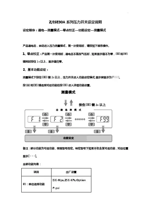
2、基本功能设定:测量模式下按住键2s 以上,压力开关进入功能设定模式,显示屏显示为。
按和键选择对应功能后按进入详细功能设置。
备注:部分功能为可选功能,根据型号而定。
特定型号下如果不包含某可选功能,对应位置显示。
全部功能列表:测量模式按住键2s 以上功 能 选 择 模 式功能设定1)F0-单位选择功能可选功能,部分型号无此功能。
单位不同,显示屏开显示的数值范围不同。
操作方法:按和键选择对应单位,按键确认。
2)F1-OUT1输出规格设定方法:此部分可设置输出类别(迟滞型/比较型)和输出模式(常开/常闭)设定。
按键进入单位选择模式按和键选择对应单位交替显示按键完成设定返回到功能选择模式,屏幕显示F0F0-单位选择功能设定完成输出模式常开型出厂时默认设置常闭型迟滞模式(出厂时默认设置)压力输出迟滞(H-1)压力输出压力输出迟滞(H-1)压力输出比较模式(也称窗口比较模式)迟滞模式(出厂时默认设置)比较模式(也称窗口比较模式)迟滞(H1)迟滞(H1)迟滞(H1)迟滞(H1)功能选择模式下按和至屏幕显示,然后按进入OUT1规格设定。
压力设定状态:此状态下设定压力开关输出的ON/OFF 点。
以迟滞型为例:输出方法:当压力超过设定值时,开关输出变为ON 。
当压力下降到设定值-迟滞(参见下图)以下时,开关输出变为OFF 。
按键 进入OUT1规格设定设定输出类别-迟滞型/比较型 按和选择对应模式。
按确认交替显示输出类别设定值迟滞型 比较型设定输出模式-常开模式/常闭模式 按和选择常开/常闭。
按确认交替显示输出模式设定值常开型 常闭型按键确认 进入压力设定状态按键 进入输出模式设定<操作方法>1、 压力设定状态进入方法 (1) 如上所述。
为更好地对静电消除器进展合理使用,对被保护对象〔除电对象〕产生积极地有益效果,科学充分的了解静电消除器产品特性及使用要求,具有重要的实际意义。
为实现此目的特编写静电消除器使用指南,此指南为整体性、原那么性文件,具体技术指标请参阅产品使用说明。
一、影响静电消除器性能的因素1、自身因素:放电方式、放电构造、高压、放电极、气体流量〔风扇类型及风速〕、产品尺寸1.2 放电构造:1.2.1离子风机:1.2.1.1 电极针与风扇的距离设置:电极针离风扇的距离变小时:1、空间离子对放电筒内场强分布影响变小;2、紊流对针积灰的作用变小;离子风机的平衡性能更加稳定。
1.2.1.2 电极针与接地电极的距离、相互的方向设置对风机性能有重大影响:电极长度方向与出风方向垂直,与地电极所在平面平行:同等条件下,消电速度慢一些。
电极长度方向与出风方向平行,与地电极所在平面垂直:同等条件下,消电速度快一些。
1.2.1.3 风扇前置与后置:风扇前置:同等条件下,消电时间慢些,平衡电压波动小一点。
风扇后置:同等条件下,消电时间快些,平衡电压波动大一点。
1.2.2 离子棒:电极针——接地电极的放电构造设计对离子棒性能会产生较大影响:接地电极过大,离子损失较大;接地电极过小放电稳定性下降。
电极针与接地极的绝缘距离有一最正确值,使离子产生量最大,损失量最小,离子利用率最大;绝缘距离过小导致电场过于集中在电极针与接地极之间,容易发生击穿造成绝缘故障;绝缘距离过大使电场力分散,容易导致平衡电压波动较大〔脉冲放电方式表现的更加明显〕。
1.3 高压高压是影响性能的主要因素,电压的上下、高压电流的大小等。
高压幅值越大,放电电流越大,消电速度越快,同时对绝缘性能的要求也越高,产品尺寸也越大。
如为脉冲工作方式,其电压越高,离子平衡波动越大。
电子密封胶的性能也非常重要,如导热性、绝缘性、密封性等。
1.4 放电极放电极的材质,外表粗糙度、锥度、形状等。
静电消除器通常在放电针上施加高电压,因此,放电针尖端局部加载了非常大的能量载荷。
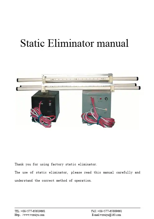
Static Eliminator manualThank you for using factory static eliminator.The use of static eliminator,please read this manual carefully and understand the correct method of operation.IntroductionThe existence of static and anti-static technology applications are increasingly affected by social concern and attention,factory production line factory technical personnel eliminator look at the Japanese import models,using a special process developed carefully.Factory production of various specifications of the eliminator with a stable performance,reliable and constant power output.At the same time using high-voltage output transformer oil-immersed type,completely overcome the similar products available on the market using epoxy resin and bitumen cast of high-voltage transformer easy to short-circuit,often sparking drawbacks,making the availability of fire discharge equipment can be prolonged output short-circuit of the advantages. WorksThe machine at work,in the discharge around the needle generate substantial positive and negative ions,when an object with static electricity pass through the plasma zone to produce and in response,and in the static objects brought to achieve the purpose of eliminating static electricity.Discharge rodDischarge stick is an essential package,discharge discharge needle stick work that is part of the high pressure from the static elimination device,discharge a high voltage is applied after the needle so that needle into the surrounding air ionization ion.In fact,the use of environmental conditions,according to the discharge in the form of rods,specification size,the length of power lines,installation methods are not uniform.Customer order should be customized after explaining in detail.Factory production of the discharge rod points directly to type and capacitive are two of them stick with the elimination of capacitive discharge effect is good,fire-retardant and do not produce the advantages of sources of interference.Product Specifications(Dimensions Unit:mm)SpecificationsOperating Voltage:AC220V±15%,50/60HZOperating ambient temperature:-10~40℃Working environment relative humidity:≤80%RHMethods of work:continuousNotes1、Eliminator Power for the exchange of220V,is strictly prohibited the use of 380V,use terminal must be reliable and machine-metal body and the ground phase, otherwise fragile Eliminator!2、Discharge rod at both ends of earth to be reliable grounding,electrostatic discharge needle to be vertically aligned objects,eliminate static electricity from the closer the better.3、Machine work,the operation of the Do not touch or near high-voltage output devices discharge needle.4、High-voltage output line and ground line is to be separated by a certain distance,and not near any metal objects.5、In a clean maintenance,you must cut off the power.6、Discharge body and fixation should always wash with gasoline Sassafras.7、In the transport,storage,use the process,no rain and exposure to corrosion objects.8、In use,if found sparks gradually weakened or non-spark output,is generally 630V, 1.5uF capacitor failure,therefore,to replace an equivalent capacitance that is back to normal.A fter-sales service1,since the date of purchase within one year from the factory to provide free maintenance service.2way for warranty repair,that is,the user shall deliver products to the factory repair.3,more than the warranty period products,such as the need to replace parts, spare parts small additional fees for nominal fee.4,all man-made damage,does not belong to the scope of the warranty,but can be sent to plant maintenance.For example:(1)failure to require the specification installation damage;(2)damage caused by force majeure.CompanyRealtek Ruian City,Zhejiang Industrial Control Instrument Factory was established in1999,is a research and development,production,marketing printing,flexible packaging,plastics and other mechanical areas of electrical automotive and industrial control equipment,professional enterprise.As a many years in industrial control equipment manufacturer,we always adhere to customer-centric in order to"quality first,the eternal purpose of the enterprise,the customer expectation is that business goal"as quality policy,in product development and technical updating the introduction of high technology,and draw on the essence of similar products at home and abroad,to provide customers with better and better products.For high-quality will be never-ending pursuit,but for customer service and will also be our relentless focus on improving one of the important work.We are the spirit of"doing my best to meet customer's needs,"the service concept,relying on high-quality products in order to price to the amount of sincerity in order to quickly win customers,with all our wisdom and sweat wholeheartedly for the customer to solve problems make every effort to meet or achieve customer requirements and expectations,and strive to be innovative and sustained through its own efforts to create value for customers in the customer satisfaction will also enable the company continue to develop and continuously improve the service system,and look forward to new and old customers with more cooperation and common development!The main products are:RY300/RY3000InverterDCZLY series DC motor winding tension(speed)control instrument(board)DC,TS,TSB,TSG,TSBG series DC motor speed control boardRTS,RTSG series DC motor controllerLJKY Series Torque Motor Controller(board)ZLMK Series Manual Tension ControllerSZK Series Manual Tension ControllerZXT Series Constant Tension ControllerSWK Series Displacement ControllerHSK Series Hall two-speed controllerZX series of counters,MetersGK Series Photoelectric correction controllerCTE-XC10Series corona processor(electronic shock machine)BF-Ⅰtype blown film makeup air controllerStatic Eliminator,etc.Distribution:Permanent magnet DC motor,torque motor,photoelectric switches,as well as packaging,plastics,printing machinery and other electronic accessory products and accessories.。

静电消除器安全操作及保养规程静电消除器是一种用于清除物体表面静电的设备,广泛应用于电子、印刷、纺织、塑料、化工等行业。
正确的使用和保养静电消除器可以维护设备的正常运行,延长使用寿命,同时也可以避免安全事故的发生。
本文将针对静电消除器的安全操作和保养规程进行详细阐述。
安全操作规程1. 前置准备工作使用静电消除器前,应按照说明书要求接好电源并确保接地良好,电源开关应处于“关闭”位置。
操作前需要着防静电服、手套及鞋,以免因静电产生火花而引发安全事故。
同时,需要检查消除器表面是否有潮湿或有遮挡物,以确保设备处于正常工作状态。
2. 操作步骤将静电消除器放置于需要清除静电的物体旁边,将吸头或风镜等设备朝向物体表面。
将电源开关打开,静电消除器开始工作。
清除完成后,关闭电源开关并拔掉电源插头,关闭设备。
3. 注意事项使用静电消除器时,需注意以下事项:•在操作前,需要检查消除器的电源、接地和防护装置是否良好,确保设备没有问题;•静电消除器应放置在稳定的平面上,避免在操作过程中设备下滑或翻倒;•在清除过程中,不要将吸头或风镜等接触物体表面,以免在静电消除过程中产生火花;•使用静电消除器时,应保持设备表面的清洁和干燥,避免设备发生故障或失效。
如果设备表面潮湿或有遮挡物,应及时清理干净。
保养规程1. 保养周期静电消除器的保养周期视使用频率而定,一般建议每隔一个月进行一次检查和清洁,重要的部件如吸头、风镜等需要每隔半年或一年更换一个新的。
2. 检查和清洁保养前需要关闭电源并拔掉电源插头。
然后,清理设备表面灰尘和污物,硅酮部位涂上润滑油,并检查吸头、风筒、风机等部件是否有损伤或堵塞,如有问题需要及时更换或修理。
3. 日常注意事项设备在使用过程中需要注意以下事项:•如发现设备异常时,需要及时停机检查,不要强行继续使用;•如发现设备散热不畅时,应停机检查并及时清理设备表面的灰尘和污物;•不要将设备放在高温、潮湿、强电磁干扰的环境下使用;•设备在停机状态下长期不用时,应关闭电源开关并拔掉电源插头;•严禁更改设备的结构和电路,以免影响设备的正常运行。
No.PS※※-OML0002CN-G 使用说明书产 品 名 称数字式压力开关形式/系列/型号ZSE30A(F)ISE30A目录安全注意事项 2型式表示·型号体系 8产品各部的名称及功能 10用语说明 11安装・设置 14设置方法 14配管方法 17配线方法 18压力的设定 21什么是测试模式 21功能设定 24什么是功能选择模式 24出厂设定 24 F0 单位切换功能 26 F1 OUT1的设定 27 F2 OUT2的设定 30 F3 响应时间的设定 30 F4显示分辨率的设定 31 F5 自动预设功能的设定 32 F6 显示值微调的设定 34 F7 省电模式的设定 35 F8 密码输入的设定 36特殊功能的设定 37 F90 全功能的设定 37 F97 复制功能的选择 39 F98 输出确认 41 F99 恢复出厂设置 43其他设定 44维护 47忘记密码的情况 48故障一览表 49规格 56规格表 56外形尺寸图 58安全注意事项此处所示的注意事项是为了确保您能安全正确地使用本产品,预先防止对您和他人造成危害和损失而制定的。
这些注意事项,按照危害和损伤的大小及紧急程度分为「注意」「警告」「危险」三个等级。
无论哪个都是与安全相关的重要内容,所以除了遵守国际规格(ISO/IEC)、日本工业规格(JIS)※1)以及其他安全法规※2)外,这些内容也请务必遵守。※1) ISO 4414: Pneumatic fluid power -- General rules relating to systemsISO 4413: Hydraulic fluid power -- General rules relating to systemsIEC 60204-1: Safety of machinery -- Electrical equipment of machines (Part 1: General requirements) ISO 10218-1992: Manipulating industrial robots-SafetyJIS B 8370: 空气压系统通则JIS B 8361: 油压系统通则JIS B 9960-1: 机械类的安全性、机械的电气装置(第1部: 一般要求事项)JIS B 8433-1993: 产业用操作机器人-安全性等※2) 劳动安全卫生法等注意:误操作时,有人员受伤的风险,以及物品破损的风险。警告:误操作时,有人员受到重大伤害甚至死亡的风险。
SMC压力开关ISE30A-01-P中文说明书
产品介绍
真空压力开关是用于检测真空压力的开关。
当真空压力未达到设定值时,开关处于断开状态。
当真空压力开关达到设定值时,开关处于接通状态,发出电信号,智慧真空吸附机构动作。
当真空系统存在泄漏、吸盘破损或气源压力变动等原因而影响到真空压力大小时,装上真空压力开关便可保证真空系统安全可靠的工作。
. 真空压力开关按功能分,有通用型和小孔口吸着确认型;按电触点的形式分,有无触点式和有触点式。
产品详细说明
工作原理一:当被测压力过额定值时,弹性元件的自由端产生位移,直接或经过比较后推动开关元件,改变开关元件的通断状态,达到控制被测压力的目的。
压力开关采用的弹性元件有单圈弹簧管、膜片、膜盒及波纹管等。
开关元件有磁性开关、水银开关、微动开关等。
工作原理二:一般是使用“电接点压力表”,这是一种普通的管弹簧压力表,加上两组电接点。
可以接通相当高低压力的电接点,从而把压力控制在上下限之间。
这种电接点的容量小,只能开关接触器的控制线圈,压力表上的控制位置可以调节。
装在水泵的出水口,当出水压力达到你的
设定值时(即你不需要更大的压力时),压力开关就动作了,水泵停止不工作。
如果压力开关一直不动作,根据你说的情况,应该是压力还没达到动作压力(压力不够)。
工作原理三:当被测压力过额定值时,弹性元件的自由端产生位移,直接或经过比较后推动开关元件,改变开关元件的通断状态,达到控制被测压力的目的。
精度:表示设备程度的值,包括线性度、公差、迟滞、重复性等.。
SMC压力传感器调整说明书ZSE30AISE30A关键信息项:1、传感器型号:ZSE30A/ISE30A2、调整目的3、调整工具4、调整步骤5、安全注意事项6、故障排除方法1、引言本协议旨在为用户提供关于 SMC 压力传感器 ZSE30A/ISE30A 的详细调整说明,以确保其正常运行和准确测量压力。
11 适用范围本协议适用于 SMC 压力传感器 ZSE30A/ISE30A 的调整操作。
2、调整目的21 确保传感器测量精度通过调整,使传感器能够准确测量压力值,减少误差。
22 适应不同的工作环境和压力范围根据实际工作需求,调整传感器的参数,以适应各种工作条件。
23 优化传感器性能提高传感器的响应速度、稳定性和可靠性。
3、调整工具31 专用调试设备如 SMC 提供的特定调试工具或软件。
32 标准压力校验仪用于提供准确的压力标准值,以校准传感器。
33 螺丝刀等常用工具用于拆卸和安装传感器的外壳及相关部件。
4、调整步骤41 准备工作411 关闭相关设备的电源,确保操作安全。
412 将传感器从系统中拆卸下来,放置在干净、平稳的工作台上。
42 外观检查421 检查传感器外壳是否有损坏、变形等情况。
422 检查传感器的连接接口是否清洁、无异物。
43 连接调试设备431 将专用调试设备或软件与传感器正确连接。
432 按照调试设备的说明书进行设置和初始化。
44 压力校准441 使用标准压力校验仪向传感器施加不同的压力值。
442 观察传感器的输出值,并与标准压力值进行对比。
443 通过调试设备调整传感器的参数,使输出值与标准压力值相符。
45 功能测试451 对调整后的传感器进行功能测试,包括压力上升和下降时的响应情况。
452 检查传感器在不同压力范围内的稳定性和重复性。
46 安装与恢复461 将调整好的传感器安装回原系统。
462 开启相关设备的电源,检查传感器的工作状态是否正常。
5、安全注意事项51 在操作过程中,务必遵循相关的安全操作规程,防止发生意外事故。
TroubleshootingSpecificationThe IODD file can be downloaded from the SMC website (URL ).Refer to the product catalogue or SMC website (URL ) for more detailed information about product specifications.DimensionsRefer to the product catalogue or SMC website (URL ) for more detailed information about dimensions.than above are displayed, please contact SMC.Error indicationSnap shot functionThe current flow rate/temperature value can be stored to the switch output ON/OFF set point.When the set value and hysteresis are set, press the UP and DOWN buttons for 1 second or longer simultaneously. Then, the set value of the sub display (right) shows [- - -], and then values corresponding to the current flow rate/temperature are automatically displayed.Peak/bottom value indicationThe max. (min.) rate/temperature when the power is supplied is detected and updated.The value can be displayed on the sub display by pressing the UP or DOWN button in measurement mode.Key-lock functionTo set this function, refer to SMC website (URL ) for more detailed information or contact us.MaintenanceHow to reset the product after a power cut or when the power has been unexpectedly removedThe settings of the product are retained from before the power cut or de-energizing.The output condition also recovers to that before the power cut or de-energizing,but may change depending on the operating environment.Therefore, check the safety of the whole system before operating the product.Function selection mode[F Select to display the function to be change [F mode to return to measurement mode.∗: The sub screen displays the content of function and the setting of the function alternately.The function number is increased and decreased by the UP and DOWN buttons.Display the required function number and press the SET button.Default settingsThe default settings are provided as follows. If these settings are acceptable,retain for use. To change setting, refer to SMC website(URL ) for more detailed information or contact us.Display of sub screenIn measurement mode, the display of the sub screen can be temporarily changed by pressing the UP or DOWN buttons.∗: After 30 seconds, it will automatically reset to the display selected in [F10].∗: Arbitrary displayThe set values and accumulated output of OUT2 cannot be displayed.(Example for 16 L/min type the above )The switch turns on within a set flow range (from P1L to P1H) during window comparator mode. Set P1L (switch lower limit) and P1H (switch upper limit) using the setting procedure above.When reversed output is selected, the main screen displays [n1L] and [n1H].To set accumulated output functions, refer to the product catalogue orSMC website (URL ) for more detailed information.For models with 2 outputs, [P_2] or [n_2] will be displayed. Set as above.For models with the temperature sensor attached, [ tn] will be displayed.When the fluid temperature falls below the set value, the output turns ON.∗: If a button operation is not performed for 30 seconds during the change of setting, the set value will start flashing.Refer to the SMC website (URL ) for more detailed information about product troubleshooting.Note: Specifications are subject to change without prior notice and any obligation on the part of the manufacturer.© 2018 SMC Corporation All Rights Reserved Akihabara UDX 15F, 4-14-1, Sotokanda, Chiyoda-ku, Tokyo 101-0021, JAPAN Phone: +81 3-5207-8249 Fax: +81 3-5298-5362URL PF ※※-OMV0007Safety InstructionsFlow (Temperature) SettingInstallationBracket mounting (PF3W704/720/740)Mount the product (with bracket) usingthe mounting screws supplied (M4 x 4 pcs.).For models with flow adjustment valve attached, fix using 8 mounting screws.Bracket thickness is approx. 1.5 mm.Measurement modeThe mode in which the flow is detected and displayed, and the switch function is operating.This is the basic operating mode; other modes should be selected for set-point and other function setting changes.Approx. 3 seconds for this period)Mounting and InstallationInstallation•Use the product within the specified operating pressure range and temperature range.•Proof pressure could vary according to the fluid temperature.Check the characteristics data for operating pressure and proof pressure.(4 pins) (Option)(Option)Direct mounting (PF3W704/720/740)Mount using the self tapping screws(nominal size: 3.0 x 4 pcs.) for installation.For models with flow adjustment valvePipingWhen connecting piping to the product, a spanner should be used on the metal piping attachment only.Using a spanner on other parts may damage the product.In particular, do not let the spanner come into contact with the M8 connector.The connector can be easily damaged.If the tightening torque is exceeded, the product can be broken. If the correct tightening torque is not applied, the fittings may become loose.Avoid any sealing tape getting inside the piping.Ensure there is no leakage from loose piping.3/824 mm 1/227 mm 3/432 mm Tighten to the specified torque for piping.The tightening torque for connection threads is shown in the table below.Direct mounting (PF3W711)Mount using the self tapping screws(nominal size: 4.0 x 4 pcs.) for installation.The tightening torque must be 1 to 1.2 Nm.The self tapping screws cannot be re-used.Refer to the outline dimension drawing for mounting hole size.Refer to the product catalogue or SMC website (URL )for more detailed information.WiringWiring of connectorConnections should only be made with the power supply turned off.Use separate routes for the Flow switch wiring and any power or high voltage wiring. Otherwise, malfunction may result due to noise.Ensure that the FG terminal is connected to ground when using a commercially available switch-mode power supply. When a switch-mode power supply isconnected to the product, switching noise will be superimposed and the product specification can no longer be met. This can be prevented by inserting a noise filter, such as a line noise filter and ferrite core, between the switch-mode power supply and the product, or by using a series power supply instead of a 141 mm How to adjust the flow rate(when a flow adjustment valve is mounted)(1) Rotate the knob of the valve to adjust the flowrate to the target value.(2) Be sure to confirm that there is no fluid leakagegenerated after adjustment.the valve several times for re-adjustment, and confirm that there is no fluid leakage.)(3) The flow adjustment valve is not designed forIf the valve is adjusted frequently, fluid may leak due to wear of the internal seal.BodyDisplayBracket mounting (PF3W711)Mount the product (with bracket) usingthe mounting screws supplied (M5 x 4 pcs.).Bracket thickness is approx. 2 mm.2. Press the UP or DOWN button to change the set value.The UP button is to increase and the DOWN button is to decrease the set value.•Press the UP button once to increase by one digit, press and hold to continuously increase.3. Press the SET button to finish the setting.•Press the DOWN button once todecrease by one digit, press and hold tocontinuously decrease.Mounting•Never mount the product in a location where it will be used as a support.•Mount the product so that the fluid flows in the direction indicated by the arrow on the side of the body.•Check the flow characteristics data for pressure loss and the straight inlet pipe length effect on accuracy, to determine inlet piping requirements.•Do not sharply reduce the piping size.•The monitor with integrated display can be rotated. It can be set at 90o intervals clockwise and anticlockwise, and also at 45o and 225o . Rotating the display with excessive force will damage the end stop.Refer to the product catalogue or SMC website (URL )for more detailed information.11/454 mm 11/254 mmBefore UseDigital Flow Switch(Integrated display type)(Integrated display type).Please read this manual carefully before operating the product and make sure you understand its capabilities and limitations. Please keep this manual handy for future reference.Safety InstructionsThese safety instructions are intended to prevent hazardous situations and/or equipment damage.These instructions indicate the level of potential hazard with the labels of"Caution", "Warning" or "Danger". They are all important notes for safety and must be followed in addition to International standards (ISO/IEC) and other safety regulations.OperatorWidth across flats of attachment<Operation>1. Press the SET button in measurement mode to display set values.Set value on the right side of the sub screen flashes.。
SAC31电容器保护测控装置技术说明书(3.70)装置的操作使用,请参见《产品使用手册》。
本说明书的内容:1. SAC31概述 (1)SAC31装置概述2. SAC31-1电容器保护测控装置 (7)SAC31-1功能说明3. SAC31-2电容器保护测控装置 (23)SAC31-2功能说明4. SAC31-3电容器保护测控装置 (36)SAC31-3功能说明5.附录A 插件E的配置应用 (49)6.附录B 插件F的配置应用 (52)7.附图概述SAC31电容器保护测控装置采用保护、测控一体化设计,适用于6~35kV电压等级的星形、三角形、双星形等各种接线型式的电力电容器,可满足保护及远动双重标准的要求。
1.1功能配置功能SAC31-1 SAC31-2 SAC31-3过流保护◆◆◆低电压保护◆◆◆过电压保护◆◆◆不平衡电压保护◆不平衡电流保护◆零序过压保护◆零序过压(三组)保护◆差电压保护◆差电流保护◆零序过流保护◆◆◆非电量保护◆◆◆接地选线◆◆◆断线判别◆◆◆故障录波◆◆◆断路器测控◆◆◆可接打印机◆◆◆注:◆表示该型号装置具备此功能。
1.2技术数据1.2.1 额定参数装置电源直流220V或110V(订货时请注明)交流电压100V交流电流5A或1A(订货时请注明)额定频率50Hz功率消耗直流电源回路:正常工作时,不大于25W;保护动作时,不大于30W交流电流回路:额定5A时每相不大于0.75VA,额定1A时每相不大于0.5VA交流电压回路:每相不大于0.5VA1.2.2 性能参数交流量测量精度电压、电流:±0.2%功率及因数:±0.5%频率:±0.01Hz过载能力测控电流回路:1.2倍额定电流时,连续工作;20倍额定电流时,允许1s保护电流回路:2倍额定电流时,连续工作;10倍额定电流时,允许10s;40倍额定电流时,允许1s交流电压回路:1.2倍额定电压时,连续工作;1.4倍额定电压时,允许10s;2倍额定电压时,允许1s直流电源回路:0.8~1.2倍的额定电压时,连续工作(装置经受过载电流/电压后,无绝缘损坏,装置性能不下降)开关量采集信号电平:直流220V或110V或24V(订货时请注明)接入方式:无源空接点SOE站内分辨率:不大于2ms脉冲量采集信号电平:直流24V脉冲要求:宽度应不小于5ms;脉冲周期不小于50ms接入方式:无源空接点或有源脉冲保护性能电流精度:±3%或±0.02 In电压精度:±3%或±0.001 Un角度精度:±5°动作时间:零时限时,不大于40ms;定时限时,±2%或±30ms出口接点容量直流220V,5A,不允许断弧绝缘性能绝缘电阻:符合DL/T478-2001中4.10.2和GB/T13729-2002中3.6.1的规定介质强度:符合DL/T478-2001中4.10.3和GB/T13729-2002中3.6.2的规定冲击电压:符合DL/T478-2001中4.10.4和GB/T13729-2002中3.6.3的规定电磁兼容性能辐射电磁场:装置能承受GB/T17626.3-1998中规定的试验等级为Ⅲ级的试验脉冲群干扰:装置能承受GB/T14598.13-1998规定的严酷等级为Ⅲ级的1MHz及100KHz试验浪涌:装置能承受GB/T17626.5-1999中规定的试验等级为Ⅳ级的试验快速瞬变:装置能承受GB/T14598.10-1996中规定的严酷等级为Ⅳ级的试验静电放电:装置能承受GB/T14598.14-1998中规定的严酷等级为Ⅳ级的试验射频传导:装置能承受GB/T17626.6-1998中规定的严酷等级为Ⅲ级的射频传导干扰试验工频干扰:装置能承受IEC60255-22-7:2003中规定的严酷等级为A级的工频干扰试验工频磁场:装置能承受GB/T17626.8-1998中规定的试验等级为Ⅴ级的工频磁场干扰试验脉冲磁场:装置能承受GB/T17626.9-1998中规定的严酷等级为Ⅳ级的脉冲磁场干扰试验传导发射:传导发射限值满足GB/T14598.16-2002中的规定机械性能振动响应:装置能承受GB/T11287-2000中3.2.1规定的严酷等级为1级的振动响应试验振动耐久:装置能承受GB/T11287-2000中3.2.2规定的严酷等级为1级的振动耐久试验冲击响应:装置能承受GB/T14537-1993中4.2.1规定的严酷等级为1级的冲击响应试验冲击耐久:装置能承受GB/T14537-1993中4.2.2规定的严酷等级为1级的冲击耐久试验碰撞:装置能承受GB/T14537-1993中4.3规定的严酷等级为1级的碰撞试验1.3装置显示及操作装置的液晶和键盘操作的详细说明,请参见《产品使用手册》。
静电消除器使用注意事项
静电棒是用于高压电之特殊制品,是消耗品,如无定期保养清理,会减短使用寿命或无法充分发挥除电效果。
1.静电棒需要确实接地,若机器铁架有施涂装者,有必要将涂装剥除,未确实接地则
无法充分发挥性能。
2.静电棒连接主机之高压线,不可与其他金属物体接触,高压线必须以绝缘材质隔离
机械之铁架,壁床15MM以上,若高压线接触金属物体者,高压线使用寿命会降短。
3.静电棒之放电针15MM以内不可有金属物,放电针尖端沾污尘时,请利用尼龙刷或
压缩空气清除。
4.静电棒为高压电输出端,请防止水滴,油滴,溶剂或可燃性粉尘,欲清除油污,可
用酒精以干净抹布擦拭。
5.静电棒正常使用,火花放电不会有目视状态,若放电针部份有火花持续发生时,请
关闭电源,将放电针清理干净后再开机,如放电异常(短路,漏电)发生时,主机高压输出不会停止,如此高压异常发生状况,长时间放置未处理时,静电棒会烧毁,因此请务必定期检视清洁保养。
静电机检测方法:
欲检测前请注意确认周围不可有可燃性溶剂,瓦斯,因检测时会有火花产生,必须考虑安全。
检测前先将电源关闭OFF,
1.将连接静电主机之静电棒高压线末端拆开,取下。
2.主机电源开关开启为ON。
3.用手持起子绝缘部份,起子金属前端接触主机外壳,末端接近高压输出端约5MM,
如有火花产生,主机是正常,若无火花,主机高压无输出。
静电除尘器操作步骤说明书一、产品概述静电除尘器是一种常用于工业生产中的空气净化设备,能够有效去除空气中的颗粒物和粉尘,提高工作环境的清洁度。
本说明书将详细介绍静电除尘器的操作步骤,以确保用户正确操作设备。
二、安全须知1. 在操作静电除尘器之前,请确保设备已经断开电源,并进行必要的维护清洁。
2. 使用静电除尘器时,应避免与设备触电,以免发生意外事故。
3. 不得将手指或其他物体伸入设备内部,以防止受伤或引发故障。
4. 若发现设备有任何异常情况或故障,请立即停止使用并联系专业人员进行检修。
三、操作步骤1. 准备工作在使用静电除尘器之前,确保以下工作已完成:- 检查电源:确保设备已连接到正常的电源供应,电源插头已牢固插入插座。
- 检查电子线路:检查设备内部的电子线路是否完好无损。
- 检查滤网:检查滤网是否干净,如有需要,可按照说明书进行清洗或更换。
- 检查电极:检查设备内部的电极是否清洁无尘,如有需要,可使用干净的软布轻轻擦拭。
2. 开始操作按下以下步骤进行静电除尘器的操作:步骤1:打开电源将电源开关拨至“开启”位置,此时设备即开始运行,电源指示灯亮起。
步骤2:调节吸风力度根据实际需要,通过旋转风量调节旋钮,调节静电除尘器的吸风力度。
旋钮向左旋转可降低吸风力度,旋钮向右旋转可增加吸风力度。
步骤3:等待过滤设备开始运行后,静电除尘器将吸入空气,并通过电极产生静电力场,颗粒物和粉尘被静电力场吸附。
此时,请耐心等待过滤过程完成。
步骤4:关闭电源使用完毕后,将电源开关拨至“关闭”位置,设备即停止运行,电源指示灯熄灭。
断开电源插头,确保设备彻底断电。
四、维护保养静电除尘器的正常维护保养能够保证其长期高效运行,请定期进行以下操作:1. 清洁滤网:根据使用情况,定期清洁或更换滤网,确保滤网清洁无尘。
具体清洁方法请参考说明书。
2. 检查电极:定期检查设备内部的电极,如发现有灰尘积累,可使用干净的软布轻轻擦拭,使其保持清洁状态。
产品名称:SMC气动产品说明书
气动是利用撞击作用或转动作用产生的空气压力使其运动或作功,气动就是以压缩空气为动力源,带动机械完成伸缩或旋转动作。
因为是利用空气具有压缩性的特点,吸入空气压缩储存,空气便像弹簧一样具有了弹力,然后用控制元件控制其方向,带动执行元件的旋转与伸缩。
从大气中吸入多少空气就会排出多少到大气中,不会产生任何化学反应,也不会消耗污染空气的任何成分,另外气体的粘性较液体要小,所以说流动速度快,也很环保。