型腔压力传感器在模具中的安装固定
- 格式:pdf
- 大小:176.20 KB
- 文档页数:4

塑料热塑性塑料材料注塑试样的制备第3部分:小方试片Plastics-Injiection moulding of test specimens ofthermoplasticmerials—Part 3:Small plates(ISO294-3;2002.IDT)目录1 范围 (4)2 规范性引用文件 (4)3 术语和定义 (4)4 设备 (5)4.1 D1型和D2型标准模具 (5)4.2注塑机 (7)5 步骤 (7)5.1状态调节 (7)5.2注塑 (7)6 试样制备的报告 (7)前言GB/T 17037塑料热塑性塑料材料注塑试样的制备分为五部分:——第1部分:一般原理及多用途试样和长条试样的制备;——第2部分:小拉伸试样;——第3部分:小方试片;——第4部分:模塑收缩率的测定;——第5部分:研究各向异性用标准试样的制备。
本部分为GB/T 17037的第3部分,本部分等同采用ISO 294-3:2002塑料热塑性塑料材料注塑试样的注塑第3部分:小方试片本部分等同翻译ISO 294-3:2002 。
本部分的附录A和附录B为资料性附录。
本部分由中国石油化工股份有限公司提出。
本部分由全国塑料标准化技术委员会石化塑料树脂产品分会归口。
本部分主要起草人:王晓丽,王树华,吴世见,陈宏愿,张昌怡。
塑料热塑性塑料材料注塑试样的制备第3部分:小方试片1 范围GB/T 17037的本部分规定了D1型和D2型两个两型腔的标准模具,用于注塑60mm∙60mm的小方试片,试片厚度为1mm(D1型)和2mm(D2型)。
试片可用于多种测试(见附录A),另外,模具可以装配嵌件用于研究熔接线对力学性能得影响(见附录B)2 规范性引用文件下列文件中的条款通过GB/T 17037本部分的引用而成为本部分的条款。
凡是注日期的引用文件,其随后所有的修改单(不包括勘误的内容)或修订版均不适用于本部分,然而,鼓励根据部分达成协议的各方研究是否可使用这些文件的最新版本。

cvc压力传感器固定方法文献The mounting method for CVC pressure sensors can be found in various literature sources, providing a range of options for securely and accurately fixing the sensor in place. CVC压力传感器的固定方法可以在各种文献来源中找到,提供了一系列选项来确保传感器安全准确地固定在位。
One common method for fixing CVC pressure sensors is the use of mounting brackets or clips, which can be specifically designed to fit the sensor and the application requirements. 一种常见的CVC压力传感器固定方法是使用安装支架或卡扣,可以专门设计以适应传感器和应用需求。
Another approach is to utilize adhesives or sealants to fix the sensor in place, providing a strong and durable bond between the sensor and the mounting surface. 另一种方法是使用粘合剂或密封剂将传感器固定在原处,为传感器和安装表面之间提供牢固持久的粘合效果。
In some cases, the use of mechanical fasteners such as screws, bolts, or clamps may be necessary to securely mount the CVC pressuresensor in place, especially in high-pressure or high-vibration environments. 在某些情况下,可能需要使用机械紧固件,如螺钉、螺栓或夹具来牢固地固定CVC压力传感器,特别是在高压或高振动环境中。


Re-write of 'Pressure Sensors in the Injection Mold' by Robert Vaughan “Pressure Sensors: The Nerve System of the Molding Process” In today’s new world mold makers must reinvent their business to add unique value to the customer as part of their offering. Adding a molding nerve center using mold pressure sensors and understanding how to use it can add a new dimension to what the mold builder brings to the table. As with anything, understanding the details involving pressure sensors and their use is key to adding value. This article will give the mold maker basic knowledge on the benefits of pressure sensors. It will also provide an understanding of the different types and styles of pressure sensors, how they are placed in the mold, and how the mold maker can utilize the nerve center during the tryout phase to reduce his costs and add capability to the ultimate customer.
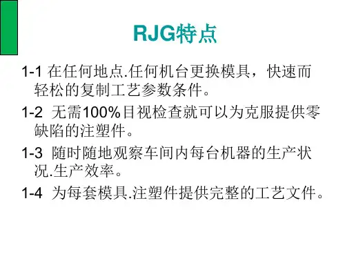
Benefits of Pressure Sensors Today most of the leading molders are utilizing pressure sensors in their business in some way. This is because the nerve center developed from the pressure sensor information can allow the molder to be more profitable by eliminating inspection costs, getting processes up and running quickly and knowing when something is abnormal so that corrective action can be taken before rejects are made. Also, the molder may want the flexibility to move molds from one press to another, or one location to another, without redeveloping the process. Mold pressure sensors allow this to be achieved. The molder is selling his press time. Someone, somewhere along the line has bid the time needed to test a new or refurbished mold before going into production. Because we are all working on tight timelines, it is important for the molder to have at his fingertips the best technology available to assist him in setting the mold and gaining valuable information. As the mold is cycled through the mold trial, information gained can then be transferred to the molder in the form of a template as shown in Figure 1.
Today the mold maker has to do more than make a rock solid mold to print. The customer wants him to build a mold with correct shrinkages that can be easily filled so critical dimensions can be easily held over time. Often the mold maker is not at the mold trial to see and learn about processing but is asked to correct molding deficiencies without really knowing how the mold was processed. Mold pressure sensors can allow the molder to see, after the fact, whether or not the process is being run as it was intended to be, so that corrective action is a result of a true need to modify a mold rather than simply to correct the process.
Purpose of Pressure Sensors Keeping it simple, pressure sensors measure plastic pressure at strategic locations along the route from the machine nozzle to the cavity as a part is filled, packed, held, and cooled. Sensors can also be placed in the machine nozzle, hot runner systems, and cold runner systems, but for the best information they are placed in the cavity areas of the mold. This is where we will focus. Sensors read pressure at their location. This information is then sent to monitoring or control systems so that the process can be better controlled from inside the cavity where the part quality is actually made. By correctly monitoring this information, recording it and developing process control approaches, the mold can be the focus of the process and can be moved from press to press with confidence that the parts can be reproduced on a machine-independent basis.
Pressure Sensor Options There are two common technologies used in mold pressure sensing. Strain gauge sensors have been predominant in the U.S. for a number of years and are probably more common. The other technology is piezoelectric technology utilizing signals generated from pressurization of quartz crystals. This technology is utilized much more in Europe than in the U.S., however, both are commonly used. While there are specific benefits to each, generally if properly employed, both technologies can give robust and accurate readings and are generally a matter of customer preference. Each technology generally requires different signal conditioning to obtain analog signals to be used by conventional data acquisition systems and inputs to the machine for the display on the machine controller.
A third option, which blurs the distinction between these two, is a digital or Lynx™ sensor from RJG. This sensor outputs digital information directly from the sensing source onto a digital network. This makes the use of each of these two technologies transparent to the user and simplifies both the setup and the calibration which many times is the key to easily adapting this technology in the field.