92对话 下一代企业级无线控制器WX5500E系列
- 格式:doc
- 大小:92.50 KB
- 文档页数:2

E22-400T22D产品规格书SX1268 433/470MHz 160mW LoRa无线模块目录第一章产品概述 (3)1.1 产品简介 (3)1.2 特点功能 (3)1.3 应用场景 (3)第二章规格参数 (4)2.1 极限参数 (4)2.2 工作参数 (4)第三章机械尺寸与引脚定义 (5)第四章推荐连线图 (6)第五章功能详解 (7)5.1定点发射 (7)5.2 广播发射 (7)5.3 广播地址 (8)5.4 监听地址 (8)5.5 模块复位 (8)5.6 AUX详解 (8)5.6.1 串口数据输出指示 (8)5.6.2 无线发射指示 (9)5.6.3 模块正在配置过程中 (9)5.6.4 注意事项 (9)第六章工作模式 (10)6.1 模式切换 (10)6.2 一般模式(模式0) (11)6.3 WOR模式(模式1) (11)6.4 配置模式(模式2) (11)6.5 深度休眠模式(模式3) (11)第七章寄存器读写控制 (12)7.1 指令格式 (12)7.2 寄存器描述 (13)7.3 出厂默认参数 (15)第八章中继组网模式使用 (15)第九章上位机配置说明 (16)第十章硬件设计 (17)第十一章常见问题 (18)11.1 传输距离不理想 (18)11.2 模块易损坏 (18)11.3 误码率太高 (18)第十二章焊接作业指导 (19)第十三章相关型号 (19)第十四章天线指南 (19)14.1 天线推荐 (19)修订历史 (20)关于我们 (20)第一章产品概述1.1 产品简介E22-400T22D是全新一代的LoRa无线模块,基于SEMTECH公司SX1268射频芯片的无线串口模块(UART),具有多种传输方式,工作在(410.125~493.125MHz)频段(默认433.125MHz),LoRa扩频技术,TTL 电平输出,兼容3.3V 与5V 的IO 口电压。
E22-400T22S采用全新一代LoRa扩频技术,与传统SX1278方案相比,SX1268方案传输距离更远,速度更快,功耗更低,体积更小;支持空中唤醒、无线配置、载波监听、自动中继、通信密钥等功能,支持分包长度设定,可提供定制开发服务。

超宽骨干,智赢未来华为NetEngine 5000E核心路由器产品外观华为NetEngine 5000E 核心路由器是面向运营商骨干网、城域网核心节点、数据中心互联节点和国际网关等推出的核心路由器产品,具有大容量、高可靠、绿色、智能等特点,支持单框、背靠背和多框集群模式,实现按需扩展,帮助运营商轻松应对互联网流量快速增长和未来业务发展。
NetEngine 5000E 集群系统包括两部分,集群中央框CCC (Cluster Central Chassis )和线卡框CLC (Cluster Line-card Chassis )。
CLC 应用于业务的高速接入,可工作在单框模式和多框集群模式;CCC 在多框集群系统中,连接CLC 的控制和数据平面,实现系统的统一管理和数据交换。
数据中心骨干网络云中心DC网关IGWDC网关云中心城域网NetEngine 5000E 2+8集群系统1华为NetEngine 5000E 集群路由器256T集群容量,弹性扩展,网络持续演进业界领先的新一代网络处理芯片更高性能和集成度、更低功耗,实现多端口类型1.6T线卡,按需部署;先进的高速架构设计创新cable背板,突破PCB背板瓶颈,SerDes速率超过56Gbps,支撑整机容量达到256T以上;CCC与CLC之间采用业界首款12通道25G高密互连光纤带,支撑1.6T多框集群;三级Clos无阻塞交换网架构三级交换分别部署在CCC及CLC上,交换单元可灵活扩展;交换矩阵全连接,信元具备动态选路能力,均衡分担到多个交换网平面,保证交换矩阵无阻塞;创新的ISHE (In-Service Hardware Expansion)技术在业务不中断的情况下引入新的线卡框,支撑集群系统从2+2按需平滑扩容至2+8;同时支持与前一代平台组成混合集群,保护客户既有投资。
全方位的可靠设计,打造高品质网络可靠的系统架构数据平面、控制平面和监控平面分离的架构设计,确保系统运行中业务、控制和环境监控互不干扰;可靠的硬件系统主控、交换网、电源以及风扇等关键组件支持冗余备份,全部组件支持热插拔,保证系统稳定可靠运行;可靠的软件系统分布式、多进程架构设计的VRP网络操作系统,将集群系统中的各种计算存储资源虚拟化为资源池,实现路由计算和存储在设备内的动态负载均衡。
©2022 Guangzhou ZHIYUAN Electronics Co., Ltd.ZM602系列Wi-Fi 模块数据手册Wi-Fi 模块DS01010101 1.2 Date:2022/9/16—————————————— 概述 ZM602系列Wi-Fi 模块是广州致远电子有限公司基于博流BL602系列芯片开发的高性能Wi-Fi+BLE 模块产品。
产品支持IEEE802.11 b/g/n 三种Wi-Fi 通信协议,支持无线热点、无线客户端、无线热点+无线客户端三种工作模式,采用20MHz 标准带宽,可以提供最大72.2Mbit/s 物理层速率。
此外,产品同时具备蓝牙通信功能,支持蓝牙5.0通信协议。
ZM602系列Wi-Fi 模块将完整的射频收发电路集成在一个模块上,同时支持Wi-Fi 和BLE 两种通信模式。
模块的射频输出支持IPEX 座连接外部天线或者直接使用模块自带的PCB 天线模块,使用十分灵活,用户可以根据自己的需求进行选择。
模块与主控设备通过UART 或者SDIO 接口进行通信,简单方便,可以帮助用户产品更快的投入市场,增加用户产品的竞争力。
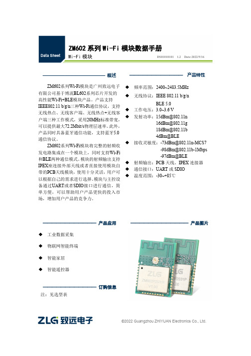
———————————— 产品应用 ◆ 工业数据采集 ◆ 物联网智能终端 ◆ 智能家居 ◆ 智能遥控器————————————— 产品图片———————————— 产品特性 ◆ 频率范围:2400~2483.5MHz ◆ 无线协议:IEEE 802.11 b/g/nBLE 5.0◆ 工作电压:3.0~3.6 V◆ 发射功率:************************** ************* 4dBm@BLE◆ 接收灵敏度:***************************************-97dBm@BLE◆ 射频输出:PCB 天线、IPEX 连接器 ◆ 通信接口:UART 或SDIO ◆ 温度范围:-30~+85℃———————————— 订购信息 注:见选型表©2022 Guangzhou ZHIYUAN Electronics Co., Ltd.修订历史文档版本 日期 原因V1.002022.04.25首次发布 V1.012022.08.17增加产品实物图; 更新产品选型表;优化产品尺寸图; 优化引脚定义说明; 更新BLE 发射功率; 新增包装信息;目录1. 产品简介 (1)1.1概述 (1)1.2产品特性 (1)1.3典型应用 (2)1.4产品选型表 (2)2. 外观尺寸 (3)3. 引脚定义 (4)3.1UART接口 (4)3.3SDIO接口 (7)4. 性能参数 (9)4.1串口波特率 (9)4.2射频性能 (9)4.3电气性能 (11)5. 硬件设计注意事项 (12)5.1UART接口系统设计 (12)5.1.1最小系统 (12)5.1.2推荐系统 (12)5.2SDIO接口系统设计 (13)5.2.1最小系统 (13)5.2.2推荐系统 (13)5.3电源设计 (13)5.4PCB布板注意事项 (14)5.5RF设计指导 (15)5.5.1外接天线使用指导 (15)5.5.2PCB天线使用指导 (15)6. 生产指导 (17)6.1推荐生产回流温度曲线 (17)6.2推荐生产回流温度时间对照表 (17)7. 包装信息 (18)8. 免责声明 (19)1. 产品简介1.1 概述ZM602系列Wi-Fi模块是广州致远电子有限公司基于博流BL602系列芯片开发的高性能Wi-Fi+BLE模块产品。

提供对802.11ax AP的管理WX2500H无线控制器在支持对传统802.11a/b/g/n/ac AP管理的同时,还可以与H3C 基于802.11ax协议的AP配合组网,从而突破传统无线网络串行通信的机制,促使无线频谱资源利用率成倍提升,有效接入用户数得到了极大的提高,有效减少无线网络的部署开销,极大提升了高密度用户环境下的用户体验。
基于全新的操作系统WX2500H系列无线控制器采用H3C新一代V7系统开发,新的操作系统极大提升产品的性能和可靠性,能够满足企业市场上越来越复杂的网络应用,相比上一代操作系统,V7系统具有多方面的优势:多核控制:在V7系统中可以根据需要调整CPU控制核和转发核的分配比例,可根据需求达到一个最佳平衡,能够充分提升CPU的控制计算及数据计算的能力,同时提供强大的并发计算能力。
支持用户态多任务:V7系统采用全新的软件运行权限控制方式,绝大多数网络业务都运行在用户态,不同网络业务占用不同的任务,每个任务占用独立的资源,某一任务运行错误只局限在本任务之内,不影响其他任务,使系统能够保持安全可靠地运行。
用户态任务监控:V7系统具有任务监控功能,系统专门监控用户态的各个任务的运行情况,如果用户态任务出现异常情况,系统会重载该任务,使业务能够迅速恢复。
采用新的单独业务升级的方式:V7系统支持单独的业务升级,只升级单独的某个业务模块而不需更新整个软件,相对公司前一代操作系统,可大大减少重启升级的次数,保证升级的安全性,有效提供网络稳定性。
提供灵活的数据转发方式传统的无线控制器部署一般采用集中式转发模式,AC可以对报文进行全面控制和安全监管,但所有的无线业务流量需要到AC进行统一处理,核心链路带宽和AC转发能力容易成为瓶颈。
特别是AP和AC通过广域网方式进行连接时,AP作为数据接入设备部署在分支机构,而AC部署在总部,所有用户数据由AP发送到AC,再由AC进行集中转发,导致转发效率低下。


Ruijie Reyee RG-RAP2260(E)Access PointDocument Version: V1.1 Date: 2023.03.02CopyrightCopyright © 2023 Ruijie NetworksAll rights are reserved in this document and this statement.Without the prior written consent of Ruijie Networks, any organization or individual shall not reproduce, extract, back up, modify, or propagate the content of this document in any manner or in any form, or translate it into other languages or use some or all parts of the document for commercial purposes., and other Ruijie networks logos are trademarks of Ruijie Networks.All other trademarks or registered trademarks mentioned in this document are owned by their respective owners. DisclaimerThe products, services, or features you purchase are subject to commercial contracts and terms, and some or all of the products, services, or features described in this document may not be available for you to purchase or use.Except for the agreement in the contract, Ruijie Networks makes no explicit or implicit statements or warranties with respect to the content of this document.The content of this document will be updated from time to time due to product version upgrades or other reasons, Ruijie Networks reserves the right to modify the content of the document without any notice or prompt.This manual is designed merely as a user guide. Ruijie Networks has tried its best to ensure the accuracy and reliability of the content when compiling this manual, but it does not guarantee that the content of the manual is completely free of errors or omissions, and all the information in this manual does not constitute any explicit or implicit warranties.PrefaceIntended AudienceThis document is intended for:●Network engineers●Technical support and servicing engineers●Network administratorsTechnical Support●The official website of Ruijie Reyee: https:///products/reyee●Technical Support Website: https:///support●Case Portal: https://●Community: https://●Technical Support Email: *****************************Conventions1. SignsThis document also uses signs to indicate some important points during the operation. The meanings of these signs are as follows:CautionAn alert that calls attention to safety instruction that if not understood or followed can result in personal injury.WarningAn alert that calls attention to important rules and information that if not understood or followed can result indata loss or equipment damage.NoteAn alert that calls attention to essential information that if not understood or followed can result in functionfailure or performance degradation.InstructionAn alert that contains additional or supplementary information that if not understood or followed will not lead to serious consequences.SpecificationAn alert that contains a description of product or version support.2. NoteThis manual provides installation steps, troubleshooting, technical specifications, and usage guidelines forcables and connectors. It is intended for users who want to understand the above and have extensiveexperience in network deployment and management, and assume that users are familiar with related terms and concepts.ContentsPreface (I)1Product Overview (1)1.1Technical Specifications (1)1.2Product Image (2)1.3LED Indicator and Button (2)1.4Power Sources (3)1.5Cooling Solution (3)2Preparing for Installation (4)2.1Installation (4)2.2Movement (4)2.3EMI (4)2.4Ventilation (5)2.5Temperature and Humidity (5)2.6Cleanness (5)2.7Power Supply (6)2.8Installation Tools (6)2.9Unpacking the Access Point (7)3Installing the Access Point (8)3.1Installation Flowchart (8)3.2Before You Begin (8)3.3Precautions (8)3.4Installing the Access Point (9)3.5Removing the Access Point (10)3.6Connecting Cables (10)3.7Bundling Cables (10)3.8Checking after Installation (11)4System Debugging (12)4.1Setting up a Debugging Environment (12)4.2Powering up the AP (12)4.2.1Checking before power-up (12)4.2.2Checking after power-up (recommended) (12)5Monitoring and Maintenance (13)5.1Monitoring (13)5.1.1Hardware Maintenance (13)6Troubleshooting (14)6.1Troubleshooting Flowchart (14)6.2Troubleshooting (14)Appendix A Connectors and Media (15)·1 Product OverviewFeaturing leading 802.11a/b/g/n/ac/ax and MU-MIMO, Ruijie RG-RAP2260(E) supports 4 spatial streams and delivers upto 800 Mbps at 2.4 GHz and 2400 Mbps at 5 GHz. The overall dual-band performance speeds up to 3200 Mbps perdevice, totally eliminating Gigabit wireless bottlenecks. RG-RAP2260(E) adopts either local power supply or PoE powersupply, and provides two Ethernet ports, making it possible connect a camera or switch device to adapt to challenges in awide variety of deployment scenarios.1.1 Technical SpecificationsTable 1-1 RG-RAP2260(E) Technical SpecificationsModel RG-RAP2260(E)RF Four-stream and dual-bandTransmissionProtocolSupport concurrent 802.11ax, 802.11ac wave2/wave1, 802.11a/b/g/nOperating Bands 802.11b/g/n: 2.4 GHz to 2.4835 GHz802.11a/n/ac/ax: 5.150 GHz to 5.250 GHz, 5.250 GHz to 5.350 GHz, 5.470 GHz to 5.725 GHz, 5.725 GHz to 5.850 GHz (Country-specific)Antenna Array antenna (2.4 GHz: 3dBi, 5 GHz: 3dBi)Spatial Streams 2.4 GHz: 4 x 4 MIMO5 GHz: 4 x 4 MIMOMax Throughput 2.4 GHz: up to 800 Mbps5 GHz: up to 2400 MbpsUp to 3200 Mbps per APModulation OFDM: BPSK@6/9Mbps, QPSK@12/18Mbps, 16QAM@24Mbps, 64QAM@48/54Mbps DSSS:DBPSK@1Mbps,DQPSK@2Mbps,**********/11MbpsMIMO-OFDM: BPSK, QPSK, 16QAM , 64QAM, 256QAM and1024QAMOFDMAReceive Sensitivity 11b: -91dBm(1Mbps), -90dBm(5Mbps), -87dBm(11Mbps)11a/g: -89dBm(6Mbps), -82dBm(24Mbps), -78dBm(36Mbps), -72dBm(54Mbps) 11n: -85dBm(MCS0), -67dBm(MCS7)11ac: 20MHz: -85dBm(MCS0), -60dBm(MCS9)11ac: 40MHz: -82dBm(MCS0), -57dBm(MCS9)11ac: 80MHz: -79dBm(MCS0), -53dBm(MCS9)11ax: 80MHz: -79dBm(MCS0), -53dBm(MCS9),-52dBm(MCS11)Transmit Power ≤100mw(20dBm) (adjustable)Transmit PowerAdjustment1 dBmDimensions(W x D x H)220 mm x 220 mm x 35 mm (8.7 in. x 8.7 in. x 1.4 in.) (excluding brackets)Weight ≤1.05 kg (excluding brackets)Service Ports One 10/100/1000BASE-T Ethernet uplink port, one 10/100/1000/2500BASE-T Ethernet uplink·port,LAN1/2.5G/PoE port is PoE+-capableManagement Ports N/ALED 1 LED (green)Power Supply Adapter: DC 12 V/2.5 A (optional)PoE: IEEE 802.3at-compliant (PoE+).Power Consumption < 25.4WTemperature Operating: 0°C to 40°C (32°F to 104°F) Storage: –40°C to 70°C (–40°F to 158°F)Humidity Operating: 5% to 95% RH (non-condensing) Storage: 5% to 95% RH (non-condensing)Installation Ceiling/wall mountCertification CEMTBF > 400,000 HWeight refers to the weight of host.1.2 Product ImageThe AP provides two Ethernet ports (LAN1/2.5G/PoE port is PoE+-capable), and one 12V DC power port for an external power supply.Figure 1-1 Appearance of RG-RAP2260(E)1.3 LED Indicator and ButtonLED Indicatorand ButtonState Frequency Meaning·LED IndicatorOff N/A The AP is NOT receiving power.Blinking0.5HzNormal operation, but there is an alarm. Fast blinking10HzPossible cases:1. Restoring the factory default settings2. Upgrading the firmware3. Restoring the image file4. Initializing the deviceSolid greenN/ANormal operation. Reset ButtonPress for less than 2 seconds Restart the device.Press for more than 5 secondsRestore the factory settings.1.4 Power SourcesThe AP can be powered either with a power adapter or through Power over Ethernet (PoE).The power adapter is customer-supplied.To use a PoE device, make sure that it supports the IEEE 802.3at standard.1.5 Cooling SolutionThe AP features a fanless design.Leave sufficient space surrounding the AP when installing the AP to permit proper airflow for ventilation.·2 Preparing for InstallationTo prevent device damage and physical injury, please read the safety recommendations carefully as described inthis chapter.Recommendations do not cover all possible hazardous situations.2.1 InstallationThe AP must be installed indoors. To ensure normal operation, the installation site must meet the following requirements.●Install the AP in a well-ventilated environment. If it is installed in a closed room, make sure there is a good coolingsystem.●Make sure the site is sturdy enough to support the AP and its accessories.●Make sure the site has enough space for installing the AP and leave sufficient room around the AP for ventilation.●Do not expose the AP to high temperature, dust, or harmful gases.●Do not install the AP in an area prone to fire or explosions.●Keep the AP away from EMI sources such as large radar stations, radio stations, and substations.●Do not subject the AP to unstable voltage, vibration, and noises.●Keep the AP at least 500 meters away from the ocean and do not face it towards the sea breeze.●The installation site should be free from water including possible flooding, seepage, dripping, or condensation.●The installation site should be selected according to network planning and communications equipment features, andconsiderations such as climate, hydrology, geology, earthquake, electrical power, and transportation.Please follow the correct method described in the installation guide to install and remove the device.2.2 Movement●Avoid frequently moving the device.●Turn off all power supplies and unplug all power cables before you remove the device.2.3 EMI●Please observe local regulations and specifications when performing electrical operations. Relevant operators mustbe qualified.●Carefully check for any potential hazards in the working area such as damp/wet ground or floors.●Find the location of the emergency power supply switch in the room before installation. Cut off the power supply firstin case of an accident.●Be sure to make a careful check before shutting down the power supply.●Do not place the device in a damp/wet location. Do not let any liquid enter the chassis.·●Keep the AP far away from grounding or lightning protection devices for power equipment.●Keep the AP away from radio stations, radar stations, high-frequency high-current devices, and microwave ovens.Any nonstandard and inaccurate electrical operation can cause an accident such as fire or electric shock, thuscausing severe even fatal damages to humans and devices.Direct or indirect contact with a wet object (or your finger) on the high voltage and power line can be fatal.2.4 VentilationFor proper ventilation, leave sufficient space around the AP.2.5 Temperature and HumidityTo ensure the normal operation and equipment service life, maintain appropriate temperature and humidity levels in theequipment room. See Table 2-1. Improper room temperature and humidity can cause damage to the device.●High relative humidity may affect insulation materials, resulting in poor insulation and even electrical leakage.Sometimes it may lead to changes in the mechanical properties of materials and corrosion of metal parts.●Low relative humidity can dry and shrink insulation sheets and cause static electricity that can damage the circuitry.●High temperatures greatly reduce device reliability and shorten service life.Table 2-1 Required Temperature and Humidity for the RG-RAP2260(E)Temperature Relative Humidity0ºC to 40ºC (32°F to 104°F) 5% to 95%2.6 CleannessDust poses a serious threat to device operation. Dust on the surface of the device can be absorbed onto metal contactpoints by static electricity causing poor contact. Electrostatic absorption of dust occurs more easily when the relativehumidity is low, and might shorten the equipment service life and cause communication failures. Table 2-2 shows themaximum concentration and diameter of dust allowed in the equipment room.Table 2-2Maximum diameter (μm)0.5 1 3 5Maximum concentration1.4×1077×1052.4×105 1.3×10⁵(Particles/m3)The amount of salt, acids and sulfides in the air are also strictly limited for the equipment room. These substances canaccelerate metal corrosion and aging of some parts. Table 2-3 describes the limits of some hazardous gases such as SO2,H2S, NO2 and Cl2 in the equipment room.Table 2-3·Gas Average (mg/m3) Maximum (mg/m3)SO20.2 1.5H2S 0.006 0.03NO20.04 0.15NH30.05 0.15Cl20.01 0.32.7 Power Supply●DC power adapter:Input voltage: 12VRated current: 2.5A●PoE+ injector: IEEE 802.3at compliantTechnical Specifications of the DC ConnectorInner DiameterOuter DiameterInsertionDepthConductorImpedanceVoltage-enduranceImpedanceVoltage-endurance(Insulator andConductor)Polarity 2.10+/-0.05mm 5.50+/-0.05mm 9mm 5Ω100MΩ1000VInner pole:positiveOuter pole:negativeThe DC input power should be greater than the power actually consumed by the system.Use DC power adapters with specifications recommended by Ruijie.Please use Ruijie certified PoE injectors.Warning:802.3af or non-standard PoE adapter may cause unknown issues. Please use Ruijie PoE+ switch or 802.3at PoE adapter as power supplier2.8 Installation ToolsCommon Tools Phillips (crosshead) screwdriver, copper and fiber cables, bolts, diagonal pliers, cable ties Special Tools Wire stripper, crimping pliers, RJ-45 crimping pliers, punch down toolMeter Multimeter, bit error rate tester (BERT)The tools listed above are customer supplied.·2.9 Unpacking the Access PointPackage ContentsItemsVerify that all parts are installed and debugged.ScrewsMounting bracketsProduct quick installation guide Packing listThe above listed items are for general situations, and contents may vary in the actual shipment. The purchasingorder shall prevail in any case. Please check each item carefully according to the packing list or purchasing order. If any item is damaged or missing, notify your sales representative.·3 Installing the Access PointThe RG-RAP2260(E) series must be fixed and installed indoors.Before installing the AP, make sure you have carefully read the requirements described in Chapter 2.3.1 Installation Flowchart3.2 Before You BeginBefore installing the AP, verify that:●The installation site provides sufficient ventilation for the AP.●The installation site meets temperature and humidity requirements.●The installation site is equipped with a proper power supply.●Network cables are in place.●The installation site meets all described requirements.●The custom AP meets customer requirements.3.3 PrecautionsTo avoid damage to the AP, observe the following safety precautions:●Do not power on the device during installation.●Install the device in a well-ventilated location.●Do not subject the device to high temperatures.●Keep away from high voltage cables.●Install the device indoors.●Do not expose the device in a thunderstorm or strong electric field.●Keep the device clean and dust-free.●Disconnect the device before cleaning it.●Do not wipe the device with a damp cloth.·●Do not wash the device with liquid.●Do not open the enclosure when the AP is working.●Fasten the device tightly.3.4 Installing the Access PointPlease install the AP in the method with a larger antenna coverage area.The antenna coverage area of ceiling-mounting is larger than that of wall-mounting indoors. Please select the formermethod.The installation process below is just for reference. The actual product prevails.●Ceiling Mount1. Attach the mounting bracket on the ceiling or wall, as shown in Figure 3-1.Figure 3-1 Attaching the Mounting Bracket on the Ceiling/Wall2. Connect the Ethernet cable to the LAN1 port. See Figure 3-2.Figure 3-2 Connecting the Ethernet Cable to the LAN1 Port3. Align the square feet on the rear of the AP over the mounting holes on the bracket. Slide the AP into the holes until itclicks into place, as shown in Figure 3-3.Figure 3-3 Fastening the AP·Install the Ethernet cables before mounting the AP on the bracket.The AP can be installed in any of four directions on the mounting bracket depending on how you route the Ethernetcable.The square feet should fit easily into the mounting slots. Do not forcibly push the AP into the slots.After installation, verify that the AP is securely fastened.3.5 Removing the Access PointHold the AP in your hands and push it upward and away from the bracket in the arrow direction, as shown in Figure 3-1.3.6 Connecting CablesConnect the UTP/STP to the LAN1 port on the AP. See Appendix A for the supported wiring for twisted pairs.Avoid bending the cable in a small radius close to the connector.Ruijie recommends that you do not use Ethernet cables with protective sleeves as they could make installation ofEthernet cables more difficult.3.7 Bundling CablesPrecautions●Make sure the cable bundles are neat and orderly.●Bend twisted pairs naturally or in a large radius close to the connector.●Do not over tighten a cable bundle as it may reduce cable life and performance.Bundling Steps1. Bundle the drop UTP/STP cables and route them to the LAN1/2.5G/PoE port.2. Attach the cables in the cable tray of the rack.3. Extend the cables under the AP and run in a straight line.·3.8 Checking after InstallationChecking the Cabinet●Make sure the external power supply matches the patch panel specifications for the cabinet.●After installation, make sure that the front and rear cabinet doors easily close.●Make sure the cabinet is stable and level.●Make sure the device and all cables are securely fastened in the rack.Checking Cable Connection●Make sure the UTP/STP cable matches the interface type.●Make sure cables are properly bundled.Checking the Power Supply●Make sure all power cables are properly connected and safe.●Make sure the AP is operational after powering on.4 System Debugging4.1 Setting up a Debugging EnvironmentUse a power adapter or PoE to power the AP.Setting up the Environment●Verify that the AP is properly connected to the power source.●Connect the AP to a wireless controller through a twisted pair cable.●When the AP is connected to a PC for debugging, verify that the PC and PoE switch are properly grounded.4.2 Powering up the AP4.2.1 Checking before power-up●Verify that the power supply is properly connected.●Verify that the input voltage matches the specification of the AP.4.2.2 Checking after power-up (recommended)After powering up, it is recommended that you check the following to ensure normal operation of the AP.●Check if any message is displayed on the Web-based configuration interface for the wireless controller.●Check if the LED works normally.5 Monitoring and Maintenance5.1 MonitoringLEDYou can observe the LED to monitor the AP in operation.5.1.1 Hardware MaintenanceIf the hardware is faulty, please contact our Technical Assistance Center (TAC) for help.6 Troubleshooting6.1 Troubleshooting Flowchart6.2 TroubleshootingLED does not light up after the AP is powered on1. If you use PoE power supply, verify that the power source is IEEE 802.11at compliant; then verify that the cable is properly connected.2. If you use a power adapter, verify that the power adapter is connected to an active power outlet; then verify that the power adapter works properly.Ethernet port is not working after the Ethernet port is connectedVerify that the device at the other end of the Ethernet cable is working properly. And then verify that the Ethernet cable is capable of providing the required data rate and is properly connected.Wireless client cannot find the AP1. First, follow the two steps above.2. Verify that the AP is correctly configured.3. Adjust the angle of the antennas.4. Move the client device to adjust the distance between the client and the AP.·Hardware Installation and Reference Guide Appendix A Connectors and MediaAppendix A Connectors and Media1000BASE-T/100BASE-TX/10BASE-TThe 1000BASE-T/100BASE-TX/10BASE-T is a 10/100/1000 Mbps auto-negotiation port that supports auto MDI/MDIX. Compliant with IEEE 802.3ab, 1000BASE-T requires Category 5e 100-ohm UTP or STP (STP is recommended) with a maximum distance of 100 meters (328 feet).1000BASE-T requires all four pairs of wires be connected for data transmission, as shown in Figure A-1.Figure A-1 1000BASE-T Connection10BASE-T uses Category 3, 4, 5 100-ohm UTP/STP and 1000BASE-T uses Category 5 100-ohm UTP/STP for connections. Both support a maximum length of 100 meters. Table A-1 shows 100BASE-TX/10BASE-T pin assignments. Table A-1 100BASE-TX/10BASE-T Pin AssignmentsFigure A-2 shows wiring of straight-through and crossover cables for 100BASE-TX/10BASE-T.Figure A-2 100BASE-TX/10BASE-T Connection。
5060Install the standInstaller le socleInstale a baseInstale la base1Connect the keyboard and mouseConnecter le clavier et la sourisConecte o teclado e o mouseConecte el teclado y el ratón2Connect the power cable andpress the power buttonConnecter le câble d’alimentation et appuyer sur le bouton d’alimentationConecte o cabo de alimentação e pressione o botão liga/desligaConecte el cable de alimentación y pulse el botón de encendido5Connect the display andpress the power buttonConnectez l’écran et appuyez sur le bouton d’alimentationConecte o monitor e pressione o botão liga/desligaConecte la pantalla y pulse el botón de encendido4Connect the network interfaceConnecter l’interface réseauConecte a interface de redeConecte la interfaz de red3o remove the SFP interface, rotate the latch and unplug it from its slot.pour retirer l’interface SFP, faites pivoter le loquet et retirez-le de son logement.para remover a interface SFP, gire a trava e retire-a do seu slot.Para extraer la interfaz SFP, gire el pestillo y desconéctelo de la ranura.RJ-45 interfaceInterface RJ-45Interface RJ-45Interfaz RJ-45Or | Ou | Ou | OSFP InterfaceInterface SFPInterface de SFPInterfaz SFPFeaturesCaractéristiques | Recursos | Funciones1. Power button/Power light2. Activity light3. USB 2.0 port (2)4. Headset port5. Wireless antenna port (optional)6. Product information tag7. +19V Power port8. Security-cable slot9. Wireless antenna port (optional)10. DisplayPort 11. DisplayPort 12. USB 2.0 port (2)13. USB 3.1 Gen 1 port (2)14. Network port, 10/100/1000 Base-Tinterface (optional)15. SFP interface (optional)1. Bouton d’alimentation/Voyantd’alimentation 2. Voyant d’activité3. Ports USB 2.0 (2)4. Port pour casque5. Port pour antenne Wi-Fi (en option)6. Étiquette d’information sur le produit7. Port d’alimentation +19 V8. Emplacement pour câble de sécurité9. Port pour antenne Wi-Fi (en option)10. DisplayPort 11. DisplayPort12. Ports USB 2.0 (2)13. Port USB 3.1 Gen 1 (2)14. Port réseau, 10/100/1000 Base-Tinterface (en option)15. Interface SFP (en option)1. Botón de encendido/Indicadorluminoso de alimentación 2. Indicador luminoso de actividad 3. Puerto USB 2.0 (2)4. Puerto para auriculares 5. Puerto para antena inalámbrica(opcional)6. Etiqueta de información del producto 7. Puerto de alimentación +19 V 8. Ranura para cable de seguridad 9. Puerto para antena inalámbrica(opcional)10. DisplayPort11. DisplayPort 12. Puerto USB 2.0 (2)13. Puerto USB 3.1 Gen 1 (2)14. Puerto de red, interfaz10/100/1000 Base-T (opcional)15. Interfaz SFP (opcional)Product support and manuals Support produits et manuels Suporte ao produto e manuais Manuales y soporte del producto/support/support/manualsContact DellContacter Dell | Entre em contato com a Dell Comuníquese con Dell/contactdellRegulatory and safetyRéglementations et sécurité | Normatização e segurança Información reglamentaria y de seguridad /regulatory_complianceRegulatory modelModèle réglementaire | Modelo normativo Modelo reglamentarioN07DRegulatory typeType réglementaire | Tipo normativo Tipo reglamentarioN07D001Computer modelModèle de l’ordinateur | Modelo do computador Modelo de computadoraWyse 50601. Botão/luz de alimentação2. Luz de atividade3. Porta USB 2.0 (2)4. Porta para fone de ouvido5. Porta da antena sem fio (opcional)6. Etiqueta de informações do produto7. Porta de alimentação de +19V8. Encaixe do cabo de segurança9. Porta da antena sem fio (opcional)10. DisplayPort 11. DisplayPort 12. Porta USB 2.0 (2)13. Porta USB 3.1 Gen 1 (2)14. Porta de rede, interface 10/100/1000Base-T (opcional)15.Interface SFP (opcional)2017-05© 2017 Dell Inc. or its rmación para NOM, o Norma Oficial MexicanaLa información que se proporciona a continuación se mostrará en los dispositivos que se describen en este documento, en conformidad con los requisitos de la Norma Oficial Mexicana (NOM):Importador:Dell México S.A. de C.V.Paseo de la Reforma 2620 - Piso 11.° Col. Lomas Altas 11950 México, D.F.Número de modelo reglamentario:N07D Voltaje de entrada:100 VAC–240 VAC Corriente de entrada (máxima): 1.7 A Frecuencia de entrada:50 Hz–60 Hz Corriente de salida: 3.34 A Voltaje de salida 19.5 V。
下一代企业级无线控制器WX5500E系列
H3C于2012年12月推出针对“云时代移动互联”应用需求的下一代企业级无线控制器WX5500E系列。
作为业内同类设备性能最突出的产品,它是第一款面向下一代企业级Wi-Fi 应用的高性能多业务智能无线控制器。
1、下一代企业级Wi-Fi架构有怎样的特点?
答:
IT消费化、云计算、移动互联等诸多技术趋势所带来的生产效率提升、投入成本降低、以及应用多元化等,使得企业网络应用从桌面、内部服务器、Intranet,不断向云端迁移。
虚拟化、自动化、移动化的变革,正在打破应用的边界,也需要新的Wi-Fi承载技术进行智能管道铺设。
区别于现有的Wi-Fi网络,将“智能、安全、易用”作为方案基础,充分融合BYOD 应用需求,成为下一代企业级Wi-Fi部属的核心特性。
同时,在超千兆Wi-Fi传输标准802.11ac即将规模商用之时,流量模型的变化,需要对无线控制架构进行优化和性能提升。
Wi-Fi核心控制的智能矩阵化,确保无论分布式或集中式的部署,都可以很好的完成802.11流量卸载,使得硬件瓶颈逐渐消失。
云内互联的大数据计算结果,可以很好的通过下一代企业级Wi-Fi这个智能管道,协同“终端、角色、业务、场景”的多种感知能力下得到呈现。
2.与H3C现有无线控制器相比,WX5500E系列无线控制器有哪些特别之处?
答:
H3C WX5500E系列控制器包括WX5540E、WX5520E两个款型,主要定位于下一代企业级Wi-Fi部署与应用。
全系配备高性能多核CPU以及高速FPGA,拥有40G的无线隧道全尺寸报文线速转发能力。
在软件方面,其基于成熟的Comware软件平台,内置H3C NEW TM无线业务引擎,提供了7x24频谱防护/监管、7层移动安全防御、无线业务智能感知、移动终端智能识别与角色安全准入、可靠视频传送、智能带宽保障、移动IPv6增强等新特性。
3. 40G的无线隧道全尺寸报文线速转发能力将会给企业级Wi-Fi部署与应用产生怎样的影响?如此出色的性能是如何做到的?
答:
目前无线业务报文的处理,主要分为两种方式:分布式本地转发与集中式隧道转发。
前者无线接入点(AP)负责大量的无线业务处理工作,仅能实现有限的业务智能管理。
而集中式隧道转发,通过无线控制器进行所有无线业务报文的转发与监管,可以支持规模化的Wi-Fi部署和无线智能应用开展。
伴随802.11n及更高速率的无线接入标准逐步商用,需要更多的关注集中转发模式下如何既能保证基于BSSID开展的无线业务特性稳定运行同时也可以有效消除用户在进行规模化Wi-Fi部署时性能瓶颈疑虑。
WX5500E系列无线控制器具备的40G的无线隧道全尺寸报文线速转发能力,将对全网Wi-Fi部署的最佳TCO获得提供有力支撑。
(如图1所示)WX5500E系列无线控制器全系列配备高速FPGA芯片,通过独立的无线二三层快速转发模块,将无线业务报文合理分配至微处理单元进行快速分析;独立的加密与监控
核心,可以保证无线转发的安全有效;内置的无阻塞交换矩阵确保线速转发能力的一致性获得。
图1 WX5500E高性能转发逻辑图
3. 请列举说明H3C NEW TM无线业务引擎特性内涵?
H3C NEW TM无线业务引擎包含RTSG、WIPS、WIAA、ROE等功能单元。
∙RTSG(RealTime Spectrum Guard)实时频谱保护
这是H3C提出的针对无线环境频谱状态的专业监控方案。
全系列无线控制器可以和内置射频采集模块的Sensor AP,实现深度融合的射频监控和实时频谱防护。
RTSG的控制台融合部署于H3C iMC智能管理中心,通过CAPWAP管理隧道,与Sensor AP 进行通信和数据采集,实现7*24小时的无线环境质量监控、无线网络能力趋势评估以及非许可干扰告警。
通过图形化方式,主动探测和识别所有2.4GHz/5GHz波段的射频干扰源(Wi-Fi 或非Wi-Fi),可提供实时FFT图,频谱密度图、光谱图、占空比图、事件光谱图、频道功率、干扰功率等;可自动识别干扰源,确定有问题的无线设备的位置,确保无线网络发挥最佳的性能。
结合H3C iAR智能报表组件,可实现全覆盖区内的射频质量历史记录的存储、追溯、回放等,自动生成客户化的趋势、合规和审计报告。
∙WIPS(Wireless Intrusion Prevention System)7层移动安全防御
WX系列无线控制器支持的移动安全防御模式有:黑名单、白名单、Rogue防御、畸形报文检测、非法用户下线、基于可预设升级的Signature MAC层攻击检测与反制(例如:DoS攻击,Flood攻击、中间人攻击)等。
配合无线应用控制台内置的海量智能专家知识库,可以获得灵活的无线安全策略判断依据,对于明确的非法攻击源(AP或终端等),实现可视的物理位置跟踪监控和交换机物理端口移除。
通过配合H3C专业核心层防火墙/IPS设备,更可以实现移动园区的7层立体安全防御,满足真正的从无线(802.11)到有线(802.3)端到端安全防护需求。
∙WIAA(Wireless Intelligent Application Aware)智能无线业务感知
WX系列无线控制器支持智能感知无线业务流量及并进行移动终端智能识别与角色安全准入,实现基于“终端类型、用户角色、业务场景”的弹性策略识别与管理,优化语音及视频业务承载。
∙ROE(RF Optimizing Expert)射频优化专家
WX系列无线控制器内置针对AP的射频优化专家(RF Optimizing Expert),通过基于特征和协议的射频优化,有效提升无线部署中高密度接入、流媒体传输等场景中的应用加速能力和质量保障效果。
其中包含:多用户公平调度、混合接入公平、过滤干扰、速率最优、频谱导航、可靠视频传送、逐包功率控制和智能带宽保障等。