沙特阿美工程规程SAEP
- 格式:pdf
- 大小:71.23 KB
- 文档页数:5
Previous Issue: 15 October 2008 Next Planned Update: 15 October 2013Revised paragraphs are indicated in the right marginPage 1 of 5 Primary contact: Ghulam, Ziad Mohammad Jamil on 966-3-8745670Engineering ProcedureSAEP-134 4 March 2009 Preparation of Saudi Aramco Engineering ProceduresDocument Responsibility: Standards CoordinatorSaudi Aramco DeskTop StandardsTable of Contents1 Scope (2)2 Applicable Documents (2)3 Instructions (2)4 Responsibilities (4)Next Planned Update: 15 October 2013 Preparation of Saudi Aramco Engineering Procedures1 ScopeSaudi Aramco Engineering Procedures (SAEPs) establish instructions andresponsibilities associated with various engineering activities. This document contains the instructions to initiate, format, prepare, revise, coordinate and obtain approvals forall SAEPs.SAEPs are procedures, approved by Saudi Aramco Management, that establishminimum requirements for dealing with their associated subject material. They aremandatory and apply on a Company-wide basis.2 Applicable DocumentsThe requirements contained in the following documents apply to the extent specified in this procedure:Saudi Aramco Engineering ProceduresSAEP-301 Instructions for Establishing and MaintainingMandatory Saudi Aramco EngineeringRequirementsSAEP-302 Instructions for Obtaining a Waiver of a MandatorySaudi Aramco Engineering Requirement3 Instructions3.1 PurposeThe purpose of a SAEP is to establish and approve a systematic method orprocess of accomplishing an engineering related activity.3.2 Organization and Contents3.2.1 The content of each SAEP is to be divided and the material organizedinto a minimum of four mandatory sections:∙Scope: This section of the procedure is normally used to describe thesubject matter of the document, including the extent of itsapplication. It can also make an overall general statementencompassing the content or functional intent of the SAEP.∙Applicable Documents: This section lists all documents that arereferenced within the procedure. Do not list documents that are notreferred to.Next Planned Update: 15 October 2013 Preparation of Saudi Aramco Engineering Procedures ∙Instructions: This section provides the procedure's instructions orguidelines to be followed.∙Responsibilities: This section establishes the responsibilities,authority and approvals associated with carrying out the procedure'sinstructions.3.2.2 Additional sections may be included as necessary, depending upon thesubject matter involved. Add more sections only when it is necessary toinclude material that does not logically fit within one of the mandatorysections.3.2.3 Appendices may be included to provide information in support of themain text of the SAEP. This may include tables, charts, graphs,examples, etc. Do not include Saudi Aramco forms in the procedure.Instead, make reference to them by their form number.Identify appendices as Appendix A, B, etc., on consecutively numberedpages. Locate appendices after the last page of the last SAEP sectionand list each appendix in the Table of Contents.3.3 Deviation from Procedure RequirementsApproval to deviate from the requirements given in a SAEP shall be obtained byfollowing the waiver instructions of SAEP-302.3.4 Cancellation of SAEPCancel existing SAEPs by obtaining the signature of the procedure's ApprovalAuthority.3.5 Document NumberingDocument numbers will be assigned to SAEPs based on the following:∙Two digit numbers: Approval by Senior Vice President∙Three digit numbers: Approval by Vice President or Chief Engineer∙Four digit numbers: Approval by Department ManagerThe mechanism of determining the document number of an engineeringprocedure will be based on the safety, cost, and maintenance and operationsimpact of the procedure. It will be supported and based on the followingfundamental nature:a) If the procedure will be utilized solely by the Saudi Aramco ResponsibleNext Planned Update: 15 October 2013 Preparation of Saudi Aramco Engineering ProceduresOrganization (who develops the procedure), a four digit number will beassigned and approval shall be by the Department Manager.b) If the procedure will be utilized by other department(s) within the sameadmin. area aside from the SARO, a three digit number will be assignedand the approval shall be by the Vice President or Chief Engineer.c) If the document will be utilized by other department(s) belonging to otherbusiness line(s), a two digit number will be assigned and the approval shallbe by the Sr. Vice President of the proponent organization.Commentary Note:The Saudi Aramco Responsible Organization (SARO) should evaluate the costimplication as a result of developing a two-digit procedure.4 Responsibilities4.1 Saudi Aramco Responsible Organization (SARO)The SARO is the department responsible for the procedure. All SAEPs musthave an assigned SARO. Specific responsibilities of the SARO include:∙Determine the need for new SAEPs, and review existing SAEPs, at least once every five (5) years per SAEP-301, to determine if they are still valid.Where required, revise procedures to achieve broadest company-wideapplication, maintain overall cost-effectiveness, ensure technical adequacy,and generally keep them up-to-date.∙Determine the approval authority for the procedure.∙Determine if company-wide input is needed for procedures containing major revisions or new SAEPs.∙Forward draft documents to the Standards Coordinator to either route for BOE review or for the completion of approval, publication, and distributionprocesses per SAEP-301 paragraph 4.7(g).∙Forward all original approval copies of procedures to the StandardsCoordinator for historical filing. Include other documents judged importantenough to be kept with the document file.4.2 Board of Engineers (BOE)∙Review SAEPs as required by paragraph 4.1, ensuring they are acceptable from the technical, safety, economic and implementation standpoint.Next Planned Update: 15 October 2013 Preparation of Saudi Aramco Engineering Procedures ∙Recommend to the Approval Authority, appropriate changes to achieve an optimum balance of technical, safety, economic and implementation factors.4.3 Approval AuthorityThe Approval Authority, determined by the SARO for each procedure, shallreview each procedure to ensure that the final procedure should be approved foruse. For documents reviewed by the BOE, ensure that all major comments havebeen resolved.4.4 Standards CoordinatorThe Standards Coordinator is responsible for the administration of all SAEPs.Specific responsibilities include:∙Maintain accurate records of all approved SAEPs, including issue dates and next planned revisions. Keep historical files and copies of all SAEPs,including original document approval signatures.∙Assign document numbers to new SAEPs.∙Establish document format and content requirements. Review all SAEPs prior to final approval for conformance to these requirements.∙Forward draft SAEPs to the BOE for review, and final revised SAEPs to the document's Approval Authority.∙Approve minor editorial changes to the procedure for such things astypographical errors, organization name and title changes approved byManagement, and reference document name changes.∙Disseminate the information of all approved SAEPs per SAEP-301paragraph 4.7(g).∙Notify SARO representatives of approaching planned revision dates insufficient time to allow an orderly review and rewrite of the procedure, ifrequired.Revision Summary15 October 2008 Revised the "Next Planned Update." Reaffirmed the contents of the document, andreissued with editorial changes.4 March 2009 Editorial revision to clarify Section 3.5 (Document Numbering).。
沙特阿美集输管道项目现场外防腐施工技术摘要:沙特阿美的质量管理体系以严格著称,承接阿美公司的管道施工项目,有必要掌握相关其质量标准和施工技术。
本文结合沙特NGCP项目实际施工经验,主要介绍了管道环焊缝防腐补口和场站工艺管道喷漆施工对于人员资质、材料选用、施工要点、检验要求以及注意事项等,以期对类似工程的施工开展提供指导和借鉴。
关键词:沙特阿美环焊缝补口工艺管道喷漆依据沙特阿美标准,油气管道和场站现场防腐必须选用APCS(Aramco Approved Coating System)体系认证的涂层系统进行防腐作业。
防腐作业工序是阿美业主最为重视的工序之一,直接影响未来油气设施的安全运行,也是项目验收阶段业主PMCC(Partial Mechanical Completion Certificate)业主给出最多需要关闭的尾项,因此对于承包商来说,不论前期还是后期,防腐施工都是影响项目成败的关键工序,必须给与足够的重视。
本文根据沙特NGCP项目施工经验和质量管理经验,结合阿美标准要求,对集输管道环焊缝补口补伤施工和场站喷漆施工技术进行介绍,以期对类似项目提供经验借鉴。
1 人员资质阿美程序文件SAEP-316要求,所有现场执行表面处理、防腐、验收作业的人员必须通过阿美认证[1]。
现场施工作业必须配备通过阿美认证的防腐机组长,专职质检员(分为一级和二级质检员),沙特NGCP项目合同要求现场配备二级质检员。
冷缠工、喷砂工、喷漆工需要通过现场演示考试,取得JCC(Job Clearance Card)卡, 方能进入作业现场进行工作。
面试和考试都需要提交证明材料和一定的时间(至少1个星期),所以根据工程进度要提前谋划和考虑。
2 现场环焊缝补口2.1 材料选用与国内工程惯常使用使用聚乙烯胶黏带不同,沙特埋地管道环焊缝补口可以应用113C系统(冷缠带)也可以使用系统113A(高粘度环氧漆)。
出于施工便利性,工程采用冷缠带施工进行补口。
Previous Issue: New Next Planned Update: 19 July 2014Page 1 of 14 Primary contact: on 966-3-8730674Engineering ProcedureSAEP-27 19 July 2009Pipelines/Piping Hydraulic Surge AnalysisDocument Responsibility: Process and Control Systems Dept.Saudi Aramco DeskTop StandardsTable of Contents1 Scope (2)2 Conflicts and Deviations (2)3 Applicable Documents (2)4 Definitions (4)5 Instructions (5)6 Responsibilities (11)Exhibits (12)Next Planned Update: 19 July 2014 Pipelines/Piping Hydraulic Surge Analysis1 ScopeThis Saudi Aramco Engineering Procedure (SAEP) provides technical guidance todefine full scope of hydraulic surge analysis during DBSP, Project Proposal, DetailedDesign and throughout the different stages of a project cycle and throughout theoperational life of a pipeline to ensure consistent approach. It provides Saudi Aramcoengineers and engineering design contractors with guidelines describing therequirements to conduct and review pipelines hydraulic surge analysis studies forexisting and new facilities.2 Conflicts and Deviations2.1 Any conflicts between this standard and other applicable Saudi AramcoEngineering Standards (SAESs) or industry standards, codes, and forms shall beresolved in writing through the Manager, Process & Control Systems Departmentof Saudi Aramco, Dhahran.2.2 Direct all requests to deviate from this standard in writing to the Company, whoshall follow internal company procedure SAEP-302 and forward such requests tothe Manager, Process & Control Systems Department of Saudi Aramco, Dhahran.3 Applicable DocumentsTo ensure compliance with the appropriate Saudi Aramco and International Standardsand Codes for over pressure protection of pipelines, the following EngineeringStandards shall be reviewed in conjunction with hydraulic surge analysis studies. These Standards encompass hydraulic analysis, surge analysis, over pressure protection ofpipelines, design pressure, materials, operating conditions, Maximum AllowableOperating Pressures and Maximum Allowable Surge Pressures.3.1 Saudi Aramco ReferencesSaudi Aramco Engineering ProceduresSAEP-12 Project Execution PlanSAEP-14 Project ProposalSAEP-302 Instructions for Obtaining a Waiver of aMandatory Saudi Aramco EngineeringRequirementSAEP-303 Engineering Reviews of Project Proposal andDetail Design DocumentationNext Planned Update: 19 July 2014 Pipelines/Piping Hydraulic Surge Analysis SAEP-354 High Integrity Protective Systems DesignRequirementsSAEP-363 Pipeline Simulation Model Development andSupportSaudi Aramco Engineering StandardsSAES-B-017 Fire Water System DesignSAES-B-058 Emergency Shutdown, Isolation, and DepressuringSAES-B-060 Fire Protection for Piers, Wharves and SeaIslandsSAES-B-064 Onshore and Nearshore Pipeline SafetySAES-B-070 Fire and Safety Requirements for Bulk PlantsSAES-J-600 Pressure Relief DevicesSAES-J-601 Emergency Shutdown and Isolation SystemsSAES-J-605 Surge Relief Protection SystemsSAES-J-700 Control ValvesSAES-L-100 Applicable Codes and Standards for PressurePiping SystemsSAES-L-132 Material Selection of Piping SystemsSAES-L-310 Design of Plant PipingSAES-L-410 Design of PipelinesSaudi Aramco Engineering ReportsSAER-5437 Guidelines for Conducting HAZOP StudiesSAER-6043 High Integrity Protection System (HIPS)Evaluation Team Report3.2 International Standards and CodesANSI/ASME Code “Process Piping” Chemical plant and petroleum refinerypipeline for in-plant pipingANSI/ASME B16.5 Pipe Flanges and Flanged FittingsANSI/ASME B31.1 Power PipingANSI/ASME B31.3 Chemical Plant and Petroleum Refinery Pipelineor In-Plant PipingNext Planned Update: 19 July 2014 Pipelines/Piping Hydraulic Surge Analysis ANSI/ASME B31.4 Liquid Petroleum Transportation Piping Systemsfor Cross-Country Liquid PipelinesANSI/ASME B31.8 Gas Transmission and Distribution PipingSystemsAmerican Petroleum InstituteAPI STD 521 Pressure-Relieving and Depressuring Systems American Water Works AssociationAWWA M45 American Water Works Association, FiberglassPipe DesignNational Fire Protection AssociationNFPA 24 Installation of Private Fire Services Mains andtheir AppurtenancesNFPA 25 Inspection, Testing and Maintenance of Waterbased Fire Protection Systems4 DefinitionsHydraulic Surge:Also referred to as “water hammer.” This is a phenomenon inpipeline operations characterized by a sudden increase in internal pressure. Hydraulicsurge is often caused by the transformation of kinetic energy to potential energy as astream of fluid is suddenly stopped.Surge Analysis: An engineering study that is undertaken to perform a hydraulic transient analysis of a specific system through the use of specialized simulation software whichmodels the system, fluid and operating conditions. The transient analysis will predict the time history of pressures and flows throughout a system as a result of potentiallyapplicable transient events. From the results, an experienced engineer/specialist candetermine whether additional surge protection is required, what form of surge protection is most suitable, its capacity and where it should be located. The surge/transient analysis referred to in this Standard is specific to pipelines/piping systems.HAZOP (Hazard and Operability): A systematic, detailed analysis technique applied to identify hazards and operability issues which have the potential to place the process plant, environment or personnel at risk. The HAZOP study identifies abnormal process deviations that may require additional protective functions. The HAZOP analysis shall follow the guidelines of SAER-5437, Saudi Aramco HAZOP Engineering Report.PHA (Preliminary Hazards Analysis): An initial screening exercise that can be used to identify, describe, and rank major hazards. This technique can also be used toNext Planned Update: 19 July 2014 Pipelines/Piping Hydraulic Surge Analysis identify possible consequences and likelihood of occurrence and providerecommendations for hazard mitigation.5 Instructions5.1 General Requirements5.1.1 PMT shall provide a copy of this Engineering Procedure to theEngineering design contractor involved in conducting the hydraulic andsurge analysis study and a full comply to this procedure shall be notifiedto the contractor.5.1.2 Risk assessment studies such as PHA or HAZOP, if available, shall beused as a basis for the surge analysis. The whole risk assessment (PHAand HAZOP) shall be an exercise in which all concerned parties(stakeholder organizations) are involved in sharing awareness andresponsibility for the decisions and assumptions made to commence thesurge analysis study. The risk assessment shall be conducted as definedin SAEP-12, SAEP-14 and SAEP-303.5.1.3 The engineering design contractor shall use the approved pipelinesimulation software that is defined in the Saudi Aramco RecommendedSimulation Software Vendor List. The approved list can be obtainedfrom P&CSD/Pipelines & Simulation Unit.5.1.4 At the completion of the hydraulic surge studies, the engineering designcontractor shall submit an electronic copy of complete simulation modelsand supporting documents to P&CSD/Pipelines & Simulation Unit, theProponent and FPD for review and approval.5.2 Surge Analysis Preparation ProceduresThe hydraulic surge analysis study shall be undertaken if over pressure ortransient risks to piping or pipelines are identified in the following phases of aproject or where changes to operating conditions are made including:1) Conceptual and Feasibility studies have been completed, detailed engineeringdesign such as DBSP, Project Proposal and Detailed Design is in progress.2) Prior to any change in existing pipeline operation or modification to thepipeline system. If the maximum flow rates or maximum operatingpressures increased from the previous operation, a new surge analysis at thenew conditions to ensure that the pipeline system is protected.3) Any change or equipment data update in the detailed design, final pipelinedesign, at the last minute, or during construction works.Next Planned Update: 19 July 2014 Pipelines/Piping Hydraulic Surge Analysis4) During commissioning and start up activities, especially for testing sectionsof the pipeline system or if the tested system is different from the standarddesign configuration.The study shall not be limited to the mentioned transient risk situations andP&CSD shall endorse the hydraulic surge analysis study timing.Before the surge analysis commences, a technical specification for the surgeanalysis study shall be prepared and approved by Proponent or SAPMT’sengineering contractor to acknowledge the problem for further assessment,scope development, and possible surge protection solution. The following listshall be completed to define full scope of the surge analysis for pipelines toensure a consistent approach for all projects.5.2.1 Analysis ObjectiveThe objective of the analysis will determine the extent of the pipelinesystem to be modeled and the accuracy of data required during pipelinemodel development and evaluation. A clear surge analysis objectiveshall be prepared and agreed with the pipeline hydraulic and surgeanalysis specialist of P&CSD prior to conducting the analysis.5.2.2 Pipeline System ScopeHydraulic surge analysis shall not be limited by project scope of work.The whole pipeline system needs to be analyzed and the model built forhydraulic surge analysis shall include all the possible causes from withinor beyond project scope boundaries and interfaces with other relatedfacilities.5.2.3 Possible Scenarios of Surge AnalysisThe transient/surge flow conditions that are expected to occur shall bedefined. The analysis shall look at various possible causes, identify thecritical cases, specify and design the necessary surge protection systemas identified during the PHA, HAZOP and surge analysis studies.Exhibit II shall be used as a checklist to identify potential causes oftransient pressure. As a minimum the following potential causes ofliquid piping overpressure shall be investigated:a) Inadvertent closure of a pipeline Class-1 or Class-2 valve.b) Closure of a downstream plant ESD valve.c) Trip of intermediate pump.Next Planned Update: 19 July 2014 Pipelines/Piping Hydraulic Surge Analysisd) Closure of one looped pipeline.e) Closure of more than one looped pipeline.f) Closure of isolation valves, inside interfacing, upstream anddownstream.g) Closure or control failure of a pipeline or downstream control valve.h) Inadvertent start of a standby pump, in addition to existing pump(s)operationi) Impact of new pipeline interfacing with existing pipeline5.2.4 Data RequirementsThe following list identifies data that shall be gathered before a surgeanalysis study is conducted:a) Pipeline system data: General description of the pipeline system,function and a summary of the likely hazard scenarios as identifiedin the PHA and HAZOP studies. Pipeline data including length,elevation profile, diameter, wall thickness, roughness or frictionfactor, elastic (Young’s) modulus, pressure rating, maximumpermissible pressure (pipes, components, joints, support), minimumacceptable pressure (pipes, components, joints, supports).b) Operating conditions: pipeline inlet pressure and temperature,arrival pressure, maximum and minimum flow rates.c) Fluid data: The key data required are the physical properties at therelevant operating pressure and temperature for the evaluatedpipeline system. Physical properties include: density, viscosity, truevapor pressure, bulk modulus, working temperature. Alternatively,for compositional analysis, the fluid composition shall be defined.d) Ambient conditions (summer/winter temperatures), thermalconductivities for pipelines and soil and/or the overall heat transfercoefficient between the pipeline and soil.e) Pumps: Type, number, location, performance characteristics, withoperating curves and the following rated conditions: (head, flow,speed, power and efficiency), Inertia of rotating elements (impeller,motor and coupling)f) Valves: Type, number, location, dynamic performance characteristic(Cv curve), open/close time, pressure rating and maximumpermissible pressure. Additional data for pressure relief valves: setNext Planned Update: 19 July 2014 Pipelines/Piping Hydraulic Surge Analysispressures for opening and closing, time needed to open and close,discharge pressure.g) Tanks: Location, general layout, dimensions, maximum, minimumand normal levels of the liquid surface, elevation relative to themain pipeline, length and diameter of the connecting piping.h) Bypass piping: Location, length, diameter, head loss.i) Surge and transient event data: Time scale of valve and pumpsoperation (Control Logic) and sequence of events to be investigated.j) Units of measurements must be consistent.5.2.5 Surge Analysis Methodology1) The analysis shall be performed first without assuming theintervention of any overpressure protection devices or equipments.Refer to Exhibit II for a list of potential causes of a transientpressure in a pipeline/piping system.2) Additional analysis shall be performed where the introduction ofmodifications to the system design are made to mitigate identifiedoverpressure conditions, e.g., trimming pump impellers, increasingpipe wall thickness, removing or modifying the device causing theexcessive transient pressures, adding overpressure protectionequipment such as relief systems as specified in SAES-J-600 andSAES-J-605 or HIPS as per Saudi Aramco Engineering Procedure& Report SAEP-354 & SAER-6043.Surge analysis shall ensure compliance with the appropriate SaudiAramco and International Standards and Codes ANSI/ASME B31.1,ANSI/ASME B31.3, ANSI/ASME B31.4, ANSI/ASME B31.8, orANSI/ASME B16.5 for over pressure protection of pipelines and processpiping. For fire water and safety related systems, surge analysis shallensure compliance with the appropriate International Standards CodesAPI STD 521, AWWA M45, NFPA 24 and NFPA 25.Surge analysis studies shall be conducted assuming that process initiatedshutdown signals triggering pump trips, due to low suction and highdischarge pressure, successfully stop pumps. This is provided that suchsignals originate from an ESD system and the signal loops and ESDsystem meet the required Safety Integrity Level (SIL) assessment anddesign requirements of SAES-J-601.Next Planned Update: 19 July 2014 Pipelines/Piping Hydraulic Surge Analysis5.2.6 Pipeline Model ValidationWhen plant and pipeline operating data is available, the model shall bevalidated against a set of operating data within the known constraints of,1) accuracy of plant measurements, 2) tolerance and convergencelimitations within the simulator, and 3) the errors associated withsimplifying assumptions made during model development. Models shallbe validated also during project proposal and/or detailed design bySAPMT’s engineering contractor.Before the data can be applied to the model, it shall be necessary toevaluate the quality of the measurements caused by faulty instruments.If available, a software package shall be used to evaluate all elements ofthe data. The software package shall reconcile the data to identify faultyinstruments and to eliminate or reduce measurements errors.Following model validation, if it is determined that the model results arenot within acceptable limits, tuning of specific parameters may berequired to improve accuracy. Model parameters may only be changed,following discussion and agreement with P&CSD. Typically, thedifference between pipeline model results and operating data can be lessthan 2%. If the discrepancies are greater than 2%, the design contractorshall submit explanations for the discrepancies to P&CSD and seekapproval to use the model for studies. This is covered by SAEP-363.5.3 Documentation RequirementsA surge analysis specific sheet shall be developed per Exhibit I and submittedfor approval prior to performing surge analysis.At the completion of the transient analysis studies, documentation shall bedeveloped containing, as a minimum requirement, the following sections:a) An executive summary that shall include a brief description of the problemunder investigation, background, objective, proposed solution, tool usedand concluding remarks.b) A system description of the pipeline and study objectives.c) A description of the model including a detailed description of thesimulation software components being used.d) A description of each scenario adopted for the study.e) Operation Control Philosophy/Logic implemented in the simulation.f) The methodology used to extract, reconcile, and filter the operating data.g) Model drawings.Next Planned Update: 19 July 2014 Pipelines/Piping Hydraulic Surge Analysish) Tabulated results for each scenario.i) Graphical results representing time plots and/or profile plots of criticalvariables to support conclusions established for each scenario.The following sections provide a detailed description of requirements for thedocumentation.5.3.1 Study ObjectiveDescribe the purpose of the study and the role that simulation plays inaddressing that purpose. The objective of the simulation must be clearlystated. The model shall be represented as a tool to help solve specificproblems or answer specific questions rather than as an end product. Thesimulation package and version used to build the model shall be defined.5.3.2 Work ScopeDescribe the system under investigation. The level of detail, modelboundaries, sources of feed…etc. This can be accomplished byreferencing available documents. Major relevant system characteristicsshould be summarized in the report that describes the simulation.5.3.3 Study AssumptionsIn order to understand the model and its limitations, all assumptions shallbe identified. Discuss the limitations of the model’s representation of theactual system and the impact those limitations have on the results andconclusions presented.5.3.4 Property PackageDescribe the thermodynamics packages that were utilized to define thefluid properties. Flow, heat transfer and pressure drop correlations mustalso be described.5.3.5 System Drawings (PFD’s, P&ID’s and Model Sketches)Provide the modeled system Process Flow Diagrams and ProcessInstrumentation Diagrams. Also, provide the simulation schematic usedto build the model and compare the simulation model with the overviewand actual pipelines/process to highlight differences.5.3.6 Model Results AnalysisPresent the calibration criteria, procedure, and results. Describe thesource of the observed data to which model results are compared.Next Planned Update: 19 July 2014 Pipelines/Piping Hydraulic Surge Analysis Explain the appropriateness of using these data for model comparisonsand the basis for any adjustments made to actual observations whenmaking the comparisons. It is important to report and use as many typesof data as possible for successful calibration of the model.5.3.7 Results Analysis Profile and TrendsProvide results analysis in profiles (specific variables vs. length ofpipeline) and trends (specific variables vs. time) for all the evaluatedcases.All the prepared document shall be submitted to P&CSD for review andapproval.6 ResponsibilitiesP&CSD provides technical guidance for all hydraulic and surge analysis, or pipelinecontrol system studies during DBSP, Project Proposal, and Detailed Design phases of a project. P&CSD proactively works with Proponent and SAPMT on pipeline design;reviews all related pipelines studies and models; and provide guidance during eachdesign stage. It is P&CSD responsibility to approve and endorse the pipeline studiesand models.SAPMT or proponent shall be responsible for obtaining approval for the surge analysis technical specification (Exhibit I) from the appropriate organizations prior toperforming the analysis. If any changes are made to the system or its operatingconditions or procedures, the technical specification shall be revised.It is the responsibility of Proponent and SAPMT to consider the implications of pipeline transient risk assessment, if the project scope is changed or it is part of a phaseddevelopment.Suppliers for pipeline and related components such as surge relief, rotating equipments shall provide Saudi Aramco and the design contractor the required equation data forconducting detailed surge analysis studies.Revision Summary19 July 2014 New Saudi Aramco Engineering Procedure.Next Planned Update: 19 July 2014 Pipelines/Piping Hydraulic Surge AnalysisEXHIBITSTABLE OF CONTENTSEXHIBIT I Surge Analysis Technical Specification – Summary SheetEXHIBIT II List of Potential Causes of Transient Pressure in a Pipeline/PipingSystem – ChecklistNext Planned Update: 19 July 2014 Pipelines/Piping Hydraulic Surge AnalysisEXHIBIT I – Surge Analysis Technical Specification – Summary SheetThe following sheet summarizes minimum surge analysis requirements for the pipeline system specified. The analysis report that follows from this is only valid for the pipeline system as defined. If any changes are made to the system or its operating conditions or procedures, the report shall be reviewed.____________________________________________________________________________ Project Name:Scope:Data Requirements: Data requirements as listed in Section 4.2 of the Procedure Design and Operating Criteria: Pipelines & Piping Design as per Saudi Aramco EngineeringStandards (SAES-L-100, SAES-L-132, SAES-L-310 andSAES-L-410)Fire and Safety related system design as per Saudi AramcoEngineering Standards (SAES-B-017, SAES-B-060,SAES-B-064 and SAES-B-070)Design Constrains:Maximum operating PressureMinimum operating PressureMaximum Flow RateMinimum Flow RateOther ParametersPipeline Transient Criteria:Maximum Transient PressureMinimum permitted pressureOther ParametersTransient Pressure Causes and scenarios List of the causes to be investigatedStudy Basic AssumptionsRecommended Surge Protection Systems This should be modified as required.Operational Requirements Constrains that should be included in the operationinstruction manualDate:Specification completed by: ______________________*Approved by:Proponent Representative ______________________P&CSD Representative ______________________* P&CSD shall decide on the approval levelNext Planned Update: 19 July 2014 Pipelines/Piping Hydraulic Surge Analysis EXHIBIT II – List of Potential Causes of Transient Pressure in a Pipeline/Piping System– Checklist____________________________________________________________________________ Item No. Possible Causes____________________________________________________________________________1. Inadvertent closure of a pipeline Class-1 or Class-2 valve as per SAES-B-058.2. Closure of a downstream plant ESD valve.3. Trip of intermediate pump.4. Closure of one looped pipeline.5. Closure of more than one looped pipeline.6. Closure of isolation valves, inside interfacing, upstream and downstream.7. Closure or control failure of a pipeline or downstream control valve as per SAES-J-700.8. Impact of new pipeline interfacing with existing pipeline.9. Inadvertent start of a standby pump, in addition to existing pump(s) operation10. The pipeline system start up and shutdown11. The lineup of the pipeline is changed12. The flow rate or capacity of the pipeline system increases/decreases13. Changes are made to the original design of the system14. Component (e.g., flow/pressure control valve, surge relief valve, etc.) malfunctions15. Basic design data (flow rates, fluid properties, materials spec., etc,) are inaccurate16. The surge protection system and control fail17. Any other potential causes that a risk assessment (PHA & HAZOP) identifies。
Previous Issue: 31 August 2002 Next Planned Update: 6 February 2016 Revised paragraphs are indicated in the right marginPage 1 of 7Primary contact: on 966-3-873-5067Engineering ProcedureSAEP-1216 February 2011Operating Instructions for New FacilitiesDocument Responsibility: Project Management Office DepartmentSaudi Aramco DeskTop StandardsTable of Contents1 Scope............................................................ 2 2 Applicable Documents................................... 2 3 Instructions.................................................... 2 4 Responsibilities. (2)Attachment 1 – Operating Instructions (4)Next Planned Update: 6 February 2016 Operating Instructions for New Facilities1 ScopeThis Saudi Aramco Engineering Procedure (SAEP) describes the format and content for initial or revised operating procedures for all new Saudi Aramco facilities that havemechanical equipment which involve regulation or control. This SAEP also assignsresponsibility for the preparation and revision of the operating procedures.2 Applicable DocumentsThe requirements contained in the following documents apply to the extent specified in this procedure.Saudi Aramco Engineering ProcedureSAEP-122Project RecordsSaudi Aramco Engineering StandardSAES-B-006Fireproofing for PlantsSaudi Aramco Safety Management GuideManagement of Change (MOC)3 InstructionsOperating Instructions shall be separate books and distributed by the Project Manager in accordance with SAEP-122.The content of Operating Instructions depends on the nature of the facility; format shall follow the general arrangement indicated in Attachment I, unless the project involvesmodifications/additions to an existing facility where the Operating Department requires the Project Manager to duplicate the format of existing manuals.4 Responsibilities4.1 New IssuesThe Engineering Contractor is responsible for the preparation of a complete,comprehensive and clear Operating Instructions for new facilities. SuchOperating Instructions shall contain all procedures required to safely start,operate, maintain and shut down the new facilities, including componentequipment. Lay-up measures for short T&I durations shall also have to beaddressed by these procedures.Next Planned Update: 6 February 2016 Operating Instructions for New Facilities Where detailed instructions and trouble-shooting procedures are contained invendor manuals, the Operating Instructions shall refer to the applicabledocuments. The project Management team and the Operating Department shallensure the above requirements are met.4.2 RevisionsThe Operating Department in consultation with Operations Engineering shall beresponsible for modifying the new instructions as required to suit actualoperating conditions when facilities are expanded or replaced by the OperationDepartment. When new installed facilities interface with existing equipment,the Engineering contractor is responsible for updating the existing operatinginstructions to reflect the new equipment and its relationship with the existingoperations. The Process & Control Systems Department, Consulting ServicesDepartment and Inspection Department shall be consulted as appropriate.All changes to process technology, chemicals, equipment, procedures, facilities,buildings or organizations at Saudi Aramco industrial facilities shall besubjected to a Management of Change (MOC) process.The Operating Department shall be responsible for providing ProjectManagement with all portions of the Operating Instructions which relate to theexisting facilities included in the project scope and identify any specificrequirements for operating instruction to be included in the contract package.4.3 ApprovalSoft copy of new Operating instructions should be submitted to the proponentfor review and concurrence with Operations teams. The Operating DepartmentManager is the final approval authority for Operating Instructions for newat least two months prior to the initial start up of new facilities.Revision Summary6 February 2016 Revised the "Next Planned Update". Reaffirmed the contents of the document, and reissuedwith minor changes.Next Planned Update: 6 February 2016 Operating Instructions for New FacilitiesAttachment 1 – Operating InstructionsI Index of Operating InstructionsII Outline for Plant as a wholeA. Introduction1. Purpose of PlantB. General Description1. Process Description2. Description of Unit Flowa) Include Plot Plan, Process Flow Diagrams, Piping and InstrumentDiagramsb) Relief and Vent Systemc) Line Designation Tables (If required by Operations)3. Description of Utilitiesa) Flow descriptions and diagrams of auxiliary systems: air, steam, water,power, fuel, etc.b) Utility Material Balances4. Control Systemsa) Distributed Control Systems (DCS)1. Control Narratives2. Logic Narrativesb) Emergency Shutdown (ESD)1. Control Narratives2. Logic Narrativesc) Management Information Systems (MIS)1. Control Narratives2. Logic NarrativesNext Planned Update: 6 February 2016 Operating Instructions for New Facilitiesd) Alarm Management Systems (AMS)1. Control Narratives2. Logic Narrativese) Fire Protection1. Equipment2. System Narratives5. Emergency Preparednessa) Emergency Preparedness Procedureb) Emergency Shutdown Systems and Alarmsc) Combustible and Toxic Gas Detection6. Overview Drawingsa) Electrical One Line Diagramb) Area Classification Diagramc) Material Selection Diagramd) Valve Operating Diagrame) Hazardous Area Diagramf) Plant LAN or other Control Network Diagramg) Plant Communication Cabling Infrastructure Diagramh) Fire Hazardous Classification Drawings as per SAES-B-006(Fireproofing for Plants)7. General Safety InstructionsC. Operating Instructions1. Preparation of detailed instructions for initial start-up2. Detailed start-up procedure3. Operating procedure logic diagrams4. Troubleshooting logic diagrams/procedures5. Detailed procedure for normal shut-down with checklist or logic diagramsNext Planned Update: 6 February 2016 Operating Instructions for New Facilities6. Detailed emergency shut-down and re-start procedures with checklist or logicdiagramsa) Equipment Failuresb) Utility Failures7. Cause and Effect Diagrams8. Plant hazards requiring special precautions9. Plant network and system securityD. General Equipment Information, Complete Facility Equipment List Including1. Individual Name2. Individual NumberE. Standby EquipmentIdentify all standby equipment and instructions for switchover as well as frequencyof switchover defined.III Outline for Individual EquipmentA. Brief description of Major Equipment1. Purpose of EquipmentB. Operating Instructions1. Preparation for initial start-up with checklist or logic diagrams2. Start-up procedure with checklist or logic diagrams3. Normal operation, including operating variables with checklist or logicdiagram4. Temporary and Emergency Operations5. Shut-down procedure with checklist or logic diagram6. Emergency shut-down procedure7. List of Consumables required for startup including dosing rates, etc.C. Operating Limitations1. Include Safety Instructions Sheets.2. Operating Parameters, Performance Criteria, allowable variances, and a list ofNext Planned Update: 6 February 2016 Operating Instructions for New Facilitiesset points for safety operations in accordance with specified operatingparameters.3. Operating Deviations, steps required to mitigate deviations.4. Consequences of process or operating deviations.5. Procedure for mitigating consequences when an exposure or loss occurs.6. Developed alarms (Process and Safety) within the control system.D. Safety Items and Operational HazardsE. Recommendations for Maintenance and Repairs by Operating PersonnelIV Support SystemsA. Corrosion Protection SystemsB. Communications Systems1. Plant network and system architecture2. Plant network and system security design3. Information technology services and interconnection4. Wireless system5. Others as applicableC. Safety Systems。
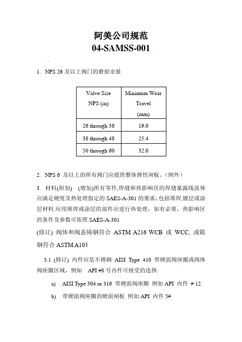
阿美公司规范04-SAMSS-001.1.NPS 26及以上阀门的磨损余量2.NPS 6 及以上的所有阀门应提供整体弹性闸板。
(例外)3.材料(附加) (增加)所有零件,焊缝和热影响区的焊缝暴露线流体应满足硬度及热处理指定的SAES-A-301的要求;包括堆焊,镀层或涂层材料.应用堆焊或涂层的部件应进行热处理,如有必要,热影响区的条件及参数可依照SAES-A-301(修订) 阀体和阀盖铸钢符合ASTM A216 WCB 或WCC, 或锻钢符合ASTM A1053.1(修订) 内件应是不锈钢AISI Type 410 带硬面阀座圈或阀体阀座圈区域,例如API #8号内件可接受的选择:a)AISI Type 304 or 316 带硬面阀座圈例如API 内件# 12.b)带硬面阀座圈的硬面闸板例如API 内件5#4.低温介质(-45 to -18°C)4.1内件须为不锈钢AISI Type 304 或316. 阀座圈须为硬面加司太立#6或等同(API STD 600 内件# 12).5.填料(附加)5.1 碳氢化合物介质下阀杆填料应是由含碳99% 的端环(John Crane - 1625G 或等同)和石墨中间环(John Crane - 237 或等同) 两种编织石墨丝组成的混合填料6.-101 to -45°C超低温介质(附加–仅指定时适用)6.1-101 to -45°C超低温介质阀门的附加a) 阀门应完全由不锈钢AISI Type 304 或316制造. 阀座圈须为硬面加司太立#6或等同(API STD 600 内件# 12).b) 体盖螺栓连接, 压盖螺栓, 压盖螺栓定位器及阀盖到支架的螺栓连接应为奥氏体不锈钢ASTM A320系列. 相应的螺母应为ASTM A194 8级系列c) (附加) 碳氢化合物介质下阀杆填料应是由含碳99% 的端环(John Crane - 1625G 或等同)和石墨中间环(John Crane - 237 或等同) 两种编织石墨丝组成的混合填料d) 泄压关闭零件的回流边上需钻3-5 mm的小孔. 阀体上应清晰标记流向.e) 泄压关闭零件的回流边上需钻3-5 mm的小孔. 阀体上应清晰标记流向.04-SAMSS-0351.水线要求1.1钢制光滑式密封面法兰垫片的接触面全,需要机械光面精整, 完成射程3.2到6.4微米2.排水管,通风口和阀体其他配件(钢阀)2.1 所有排泄阀门及相关管道零件抗耐腐蚀至少相当于内件材料,最低标准为AISI 316L SS3.材质3.1 当对焊连接阀门用碳钢和最低屈服强度289 MPa (42,000psi)或更高,最高碳含量不得超过0.26%.对于编织阀门,这种限制仅适用于端口。
Previous Issue: 28 April 2009 Next Planned Update: 22 May 2016Revised paragraphs are indicated in the right marginPage 1 of 15Primary contact: Maatoug, Maatoug A on 966-3- 8747960Engineering ProcedureSAEP-2222 May 2011Tank Calibration RequirementsDocument Responsibility: Custody Measurement Standards CommitteeSaudi Aramco DeskTop StandardsTable of Contents1 Scope............................................................2 2 Conflicts and Deviations................................ 23 Applicable Documents................................... 24 Definitions and Acronyms.............................. 35 Instructions.................................................... 56 Responsibilities.............................................. 87 Activity Matrix.............................................. 10 Attachment I – Required Information on the Tank Capacity Table................. 12 Attachment II – Qualifications of theThird Party Inspection Agency (15)Next Planned Update: 22 May 2016 Tank Calibration Requirements 1 ScopeThis procedure establishes the instructions and responsibilities for the calibration ofall Saudi Aramco royalty/custody tank gauging applications. This procedure is alsoapplicable to the inventory tanks that have the potential to be used for custody orroyalty measurement applications in case of the metering system failures. Organizations for which responsibilities are specified include, but are not limited to:∙The Proponent Organization∙Saudi Aramco Project Management Team (SAPMT)∙Process & Control Systems Department (P&CSD)2 Conflicts and Deviations2.1 Any conflicts between this procedure and other applicable Saudi AramcoEngineering Standards (SAESs), Materials System Specifications (SAMSSs),Standard Drawings (SASDs), or industry standards, codes, and forms shall beresolved in writing by the Manager, Process & Control Systems Department ofSaudi Aramco, Dhahran.2.2 Direct all requests to deviate from this procedure in writing in accordance withSAEP-302 to the Manager, Process & Control Systems Department of SaudiAramco, Dhahran.2.3 Direct all requests for interpretation of this procedure in writing to the Chairman,Custody Measurement Standards Committee for resolution. The Chairman,Custody Measurement Standards Committee shall be solely responsible fordetermining whether a proposed request meets the requirements of this procedure.3 Applicable DocumentsThe procedures covered by this document shall comply with the latest edition of thereferences listed below, unless otherwise noted:3.1 Saudi Aramco ReferenceSaudi Aramco Engineering ProcedureSAEP-302Instructions for Obtaining a Waiver of aMandatory Saudi Aramco EngineeringRequirementNext Planned Update: 22 May 2016 Tank Calibration Requirements3.2 Industry Codes and StandardsAmerican Petroleum Institute (API) Manual of Petroleum MeasurementStandards (MPMS)Chapter 2.2A Measurement and Calibration of UprightCylindrical Tanks by the Manual StrappingMethodChapter 2.2B Calibration of Upright Cylindrical Tanks usingthe Optical-Reference Line MethodChapter 2.2C Calibration of Upright Cylindrical Tanks usingthe Optical-Triangulation MethodChapter 2.2D Calibration of Upright Cylindrical Tanks usingthe Internal Electro-optical Distance RangingMethodChapter 2.2E Calibration of Horizontal Cylindrical Tanks-Part 1: Manual MethodsChapter 2.2F Calibration of Horizontal Cylindrical Tanks-Part 2: Internal Electro-Optical Distance-Ranging MethodStandard 2552 Method for Measurement and Calibration ofSpheres and SpheroidsStandard 2555 Liquid Calibration of Tanks4 Definitions and Acronyms4.1 DefinitionsApprove: Review and formal acceptance characterized by the signature of thefinal authorizing individual or organization.Capacity Table: A table often referred to as a tank capacity table or calibrationtable, showing the capacities of or volumes in a tank for various liquid levelsmeasured from the reference gauge point.Critical Zone: The region between initial and complete flotation of a floatingroof.Custody Transfer Measurement: A specialized form of measurement thatprovides quantity and quality information used for the physical and fiscaldocumentation of a change in ownership and/or responsibility of hydrocarboncommodities. This includes measurement of hydrocarbon liquid movementsNext Planned Update: 22 May 2016 Tank Calibration Requirements(deliveries or receipts) between Saudi Aramco and its customers, suppliers, jointventures and transport contractors including VELA ships.Customer: The party that takes ownership or responsibility of a hydrocarboncommodity from Saudi Aramco.Datum plate: A level metal plate located directly under the reference gaugepoint to provide a fixed contact surface from which liquid depth measurementcan be made.Deadwood: Deadwood refers to any object within the tank, including a floatingroof, which displaces liquid and reduces the capacity of the tank; also anypermanent appurtenances on the outside of the tank, such as cleanout boxes ormanholes, which increase the capacity of the tank. Deadwood is positive if itincreases tank capacity or negative if it decreases capacity.External Floating Roof: A cover over an open top storage tank consisting of adeck which rests upon the liquid being contained.Internal Floating Roof: A cover within a fixed roof tank which rests upon thepetroleum liquid being contained.Master Tape: A tape that is used for calibrating working tapes for tankmeasurements and is identified with a report of calibration at 68°F (20°C) and aspecific tension designated by the National Institute of Standards andTechnology (NIST) or an equivalent international standard organization.Recomputation: The process of re-generating the capacity tables through softcalculations, without repeating the field calibration measurements. It involves,simply, updating or revising the capacity table using previously established tankdiametersReference Gauge Height: The distance from the datum plate or tank bottom tothe reference gauge point.Royalty Measurement: A specialized form of measurement that is used as thebasis for paying royalty to the Saudi Arabian Government.SAP: The Saudi Aramco main system for enterprise resource management.Spheres: A stationary liquid storage tank, supported on columns so that theentire tank shall be aboveground.Spheroid: A stationary liquid storage tank having a shell of double curvature.Any horizontal cross-section is a series of circular arcs.Next Planned Update: 22 May 2016 Tank Calibration Requirements Strapping: The measurement of the external circumference of a vertical orhorizontal cylindrical tank by stretching a steel tape around each course of thetank's plates and recording the measurement.Tank Calibration: The process of determining the capacity of a tank throughfield measurements.Third Party Inspection Agency: An independent inspection agency whosefunction is to conduct an unbiased inspection of certain systems, equipment,materials, etc., against a set of standards, guidelines or procedures. For purposesof this SAEP, the Third Party Inspector has particular knowledge of andexperience of conducting tank calibration in accordance with industry custodymeasurement standards and procedures.4.2 AbbreviationsAPI American Petroleum InstituteCMU Custody Measurement Unit of Process & Control SystemsDepartmentEODR Electro Optical Distance RangingORLM Optical Reference Line MethodMPMS Manual of Petroleum Measurement StandardsP&CSD Process & Control Systems DepartmentSA Saudi AramcoSAEP Saudi Aramco Engineering ProcedureSAES Saudi Aramco Engineering StandardSAMSS Saudi Aramco Material SpecificationSAP Systems Application ProgrammingSASD Saudi Aramco Engineering Standard Drawing5 Instructions5.1 GeneralThis procedure shall be used in conjunction with existing international standardsand is not intended to replace the standards referred to in Section 3 above.The reference temperature for all tank capacity tables shall be 60°F forRefineries, Terminals, Gas Plants and 15°C for Distribution Operations.Next Planned Update: 22 May 2016 Tank Calibration Requirements5.2 Calibration/Re-calibration FrequenciesAll new tanks/vessels used for custody transfer measurement must undergocalibration prior to being put in service.All tanks/vessels must be recalibrated in conjunction with Testing andInspection (T&I), or when a major repair is don for tank bottom.The upright cylindrical tank shall be recalibrated in accordance within volume detected to invoke this appendix requirement.5.3 Precalibration PreparationsPrior to calibration, the upright cylindrical tanks, horizontal tanks, spheres andspheroids must have been filled to 95% of their design operating capacity for aminimum period of 24 hours with a liquid at least as dense as the product theywill normally store.Commentary Note:This requirement is considered met if the tank/vessel has been already hydro-tested.5.4 Recomputation RequirementsThe capacity table of horizontal tanks, spheres and spheroids must berecomputed if variation in product operating temperatures and temperatureassumed during calibration is greater than 11°C (20°F).Commentary Note:Variations in the product's calibration specific gravity and operating specificgravity greater than 20% will require a recomputation of the table, due to thehydrostatic head effect expansion on tanks/vessels.Floating roof correction table requires recomputation when any variation in theroof's weight, due to repairs or modifications, results in a change in the roofdeadweight that altered the tank predetermined volume by 0.02% or more.Commentary Note:While recalibration involves reestablishing tank diameters through standardcalibration methods and developing new tank capacity tables for custody andnon-custody transfers, recomputation, involves simply updating or revising thecapacity table using previously established tank diameters.Next Planned Update: 22 May 2016 Tank Calibration Requirements5.5 Acceptable Calibration TechnologiesFollowing is a list of the calibration technologies acceptable for tank/vesselcalibrations along with the reference standard the methods' implementationshould comply to. The methods are arranged in the order of priority, based onthe most efficient means of calibration for a given set of conditions.(1) Internal Electro Optical Distance Ranging Method (EODR),API Chapter 2.2D(2) Internal Electro Optical Distance Ranging Method (EODR),API Chapter 2.2F(3) Optical Reference Line Method (ORLM), API Chapter 2.2B(4) Manual Strapping Method(Strapping), API Chapter 2.2A(5) Optical Triangulation Method, API Chapter 2.2C(6) Manual Methods, API Chapter 2.2E(7) Liquid Calibration, API 2555(8) Method for Measurement and Calibration of Spheres and Spheroids,API STD 2552Commentary Note:All these methods essentially provide alternate techniques for measuring tankdiameters. While manual strapping is limited to external calibrations, theremaining methods can be used either externally or internally.5.6 Technology Selection Guidelinesa. The application of the EODR shall be limited to tanks/vessels that aregreater than 5 meters in diameter.b. The application of liquid calibration shall be limited to tanks/vessels thatare smaller than 5 meters in diameter.c. If a tank/vessel is insulated, it should be calibrated internally.d. External and internal EODR shall be used for all tanks/vessels that aregreater than 5 meters in diameter with no insulation.e. Either Internal or external ORLM shall be used for floating roof tanks.f. External ORLM can be used for fixed roof tanks with no insulation andhaving not more than a single wind girder.g. If the tank has multiple external wind girders, it should be calibrated eitherby external/internal EODR or internal ORLM.Next Planned Update: 22 May 2016 Tank Calibration Requirementsh.bottom elevations shall be sighted along radii every 45 degrees. Alongthese radii, elevations should be obtained at equally spaced intervals notmore than 10 feet (3 meters) from the tank's center to its shell. Liquidcalibration method is permitted to be used whenever the tank containsirregular shaped deadwood (e.g., steam coils, etc.).i. Spheres and spheroids shall be calibrated in accordance with API STD2552, Method for Measurement and Calibration of Spheres and Spheroids.6 ResponsibilitiesThe Saudi Aramco organizations with tank/vessels calibration responsibilities shallensure that their personnel become familiar with this SAEP.6.1 Saudi Aramco Project Management Team (SAPMT)a. Initiate calibration request for new tanks/vessels,b. Inform CMU of the calibration of new tanks only if is used for royaltytransfer,c. Request list of Approved Third Party Inspection Agencies,d. Contract tank calibrations to an approved Third Party Inspection Agency,e. Inform the Proponent to witness the calibration process,f. Obtain the capacity tables from the Third Party Inspection Agency,g. Request CMU's review for capacity tables of new royalty tanks,h. Provide two hardcopy and two electronic tables in US Customary unitsand/or (based on application requirement) SI units of the final approvedcalibration calculation and the capacity table to the Proponent.i. Close the activity.6.2 The Proponent Organizationa. Initiate requests for in-service tanks/vessels per the frequencyrequirements set forth in Section 5.2 above,b. Inform CMU of the calibration of new tanks if it is used for royaltytransfer applications,c. Request list of the approved Third Party Inspection Agencies,d. Contract tank calibrations to an approved Third Party Inspection Agency,e. Provide the operating data (operating temperature, density at operatingtemperature, operating pressure) to the Third Party Inspection Agency,Next Planned Update: 22 May 2016 Tank Calibration Requirementsf. Ensure the equipment used has been calibrated and has valid certificatesthat are traceable to National Institute of Standard and Technology (NIST)or other approved standards organization,g. Witness the field calibration process and ensure that the Third PartyInspection Agency is performing the tank/vessel calibration calculations inaccordance API MPMS Chapter 2.2A and API STD 2552, including, butnot limited to, the following capacity table correction factors,i. master tape corrections.ii. working tape correction.iii. tape rise correction.iv. tank shell temperature expansion correction.v. hydrostatic head effect correction.vi. tilt correction.vii. floating roof gravity adjustment.h. Consult with CMU if a technical inquiry about the calibration and/ordocumentation process cannot be resolved internally,i. Review the draft calibration calculations,j. Review the produced capacity tables and make sure they comply with the requirements in Attachment I,k. Submit the capacity tables for the calibration of the new tanks to theSAPMT,l. Submit initial capacity tables of new royalty tanks only to CMU forreview.m. Maintain two hardcopy and two electronic tables in US Customary units and/or (based on application requirement) SI units of the final approvedcalibration calculation and the capacity table to the proponent,n. Update the SAP Tank Gauging System with the new approved capacitytable, if applicable,o. Inform the SAPMT of the completion of the tank calibration,p. Commission the tank,q. Close the activity.6.3 Process & Control Systems Department (P&CSD)The Process & Control Systems Department/Custody Measurement Unit (CMU)is responsible for providing technical assistance to the Proponent(s) on mattersNext Planned Update: 22 May 2016 Tank Calibration Requirements pertaining to tank calibrations. Specific responsibilities of CMU aresummarized below:a. Review the qualifications of the Third Party Inspection Agencies and makesure they meet all of the requirements detailed in Attachment II.b. Maintain the list of Approved Third Party Inspection Agencies.c. Submit the list of the Approved Third Party Inspection Agencies to theSAPMT and the Proponent upon request.d. Upon request from the proponent, provide consultation if a technicalinquiry about the calibration and/or documentation process cannot beresolved internally.e. Review initial capacity tables of new royalty tanks only.7 Activity MatrixThe following matrix summarizes the general sequence of activities and corresponding responsible organizations for calibrating tanks. Detailed requirements for eachorganization are specified in Section 6.Next Planned Update: 22 May 2016 Tank Calibration RequirementsNote:(1) SAPMT initiates calibration request for new tanks/vessels. The Proponent initiates calibrationrequest for tanks/vessels in-service per the frequency requirements set forth in Section 5 above.For BI-1900, the proponent will assume the responsibilities of SAPMT.Revision Summary22 May 2011 Revised the "Next Planned Update". Reaffirmed the contents of the document, and reissuedwith minor changes.Next Planned Update: 22 May 2016 Tank Calibration Requirements Attachment I – Required Information on the Tank Capacity TableThe final capacity table should contain the following minimum documentation details:1. Tank Identificationa. The site or installation tank numberb. Location Titled with “Saudi Arabian Oil Company”c. The type of tank in serviced. The name of the plant, owner or operatore. The name and address of the calibration authority or company which carriedout the calibration.2. Product InformationThe product name and density of the liquid stored in the tank when in service andused in the computation of the tank capacity tables.3. Operational Detailsa. The standard temperature (60°F for U.S. Customary, or 15°C for metrictables) for which the tank capacity table has been calculated.b. Operating temperature and pressurec. Table type (innage or ullage)4. Traceability and Tracking Detailsa. The date a new tank was first calibratedb. The date an old tank was recalibratedc. Calibration agent reference document numberd. The date the tank was recomputed, and the method used for recomputatione. The date of the calibration along with specific references to the methodadopted in calibrating the tank bottomf. Page numberg. Reference to the standard on which the calibration is basedh. The Third Party Inspection Agency shall sign and stamp each page of thecertificate.Next Planned Update: 22 May 2016 Tank Calibration Requirements5. Tank Dimensionsa. The nominal height and diameter of the tankb. Description of the tank bottom type, along with the method used todetermine the bottom volumec. Integrated deadwood, accurately accounted for as to location and volume,and included as an attachmentd. Note on capacity table that the volume below the striking plate is included inthe first measuremente. The shell height, is measured as the vertical distance between the bottom ofthe bottom angle and top of the top angle and measured near the referencegauge hatchf. Reference height measurement point locations shall be clearly identified ontank capacity tablesg. The height of the datum-points(s) with reference to the junction of the tankshell and bottom platingh. If an automatic gauging system is installed, the height of the gauge datumpoint with reference to the junction of the tank shell and bottom platingi. Maximum fill heightj. Safe fill height specified by the tank ownerk. The amount of tilt in shell height is measured and recorded.l. Height of the striking point (datum plate) from the tank bottom platem. The decimal (fraction) average volume for each strapping page.6. Floating Roof Informationa. The allowance for the roof is to be treated as deadwood and incorporated inthe tank capacity table directly, not as a separate attachmentb. The density of the liquid for which the roof has been calculated shall berecorded on the table directlyc. The apparent mass in air of the roof and accessoriesd. The displacement volume of the roof and the floating roof correction factormethod statemente. A defined level (Level A), with the distance above the dip point designatingwhere the roof is at restf. A defined level (Level B), with the distance when the roof is just fullyfloating in the lowest-density liquid to be contained in the tankNext Planned Update: 22 May 2016 Tank Calibration Requirementsg. The part of the capacity table between Level A and Level B is marked as“Not Accurate”h. Critical zones shall be identified within the tablei. The range where floating roof adjustment not to be performed.7. Tank Shell Correctiona. A shell temperature expansion factor table is to be developed in incrementsof 5°F or 3°C and included as an attachment to the capacity table for aspecific operating range.b. Include the equation for determining the shell temperature.Next Planned Update: 22 May 2016 Tank Calibration Requirements Attachment II – Qualifications of the Third Party Inspection AgencyThe Third Party Inspection Agency shall meet all of the following requirements:1. The agency has provided similar services for a minimum of 3 years. It shallsubmit a list of companies for which it has provided similar calibration servicesover the preceding 3 years.2. The agency's personnel performing the field measurements and calculations musthave a minimum of one year experience with the application of the APItank/vessel calibration standards. Experience shall be documented by submittal ofresume and verifiable work histories.3. The agency shall have written procedures which meet the requirements of APItank/vessel calibration standards. It shall submit the written procedures forreview.4. The agency shall have equipment as specified in API MPMS Chapter 2.2. It shallsubmit a list of the equipment it intends to use along with corresponding validcalibration certificates.5. The agency shall demonstrate it is ISO-certified and that it is activelyadministering a quality assurance program. It shall submit a copy of its ISOcertification and his quality assurance program details for review.6. The agency shall demonstrate that it is capable of performing the tank/vesselcalibration calculations. It shall provide a minimum of two samples of previouscalibration results, including field data and all calculations.7. The agency shall provide financial and insurance documentations as deemednecessary by the Contracting Unit to ensure he has adequate liability coverage fordamages done to Saudi Aramco facilities.。
Previous Issue: 31 May 2003 Next Planned Update: 20 October 2014Page 1 of 14Primary contact: Al-Sabti Tareq Ibrahim on 966-3-8760236Engineering ProcedureSAEP-35220 October 2009Welding Procedures Review and Approval Welding Standards Committee MembersAwwami, Adnan Ni'Mah, Chairman Rao, Sanyasi, Vice Chairman Carrera, R LCarswell, Raymond J. Juraifani, Hatim Hamad Keen, Peter DavidMuslim, Husain Muhammad Nasri, Nadhir Ibrahim Niemeyer, Dennis Charles Sabti, Tareq IbrahimSayed Nasir, Ghalib TaherSaudi Aramco DeskTop StandardsTable of Contents1 Scope.............................................................2 2 Conflicts and Deviations................................. 23 Applicable Documents.................................... 24 Definitions and Acronyms............................... 6 5Instructions and Approval Responsibility (7)Table 1 – Welding Procedure Technical Approval Responsibility………..……….. 9 Appendix I – Welding Master Set Preparation and Approval..................... 12 Appendix II – Welding Package Review and Approval Process for Company Projects................................ 13 Appendix III – Welding Package Review and Approval Process forRepair/Maintenance/Alterations (14)Next Planned Update: 20 October 2014 Welding Procedures Review and Approval1 Scope1.1 This procedure specifies the responsibilities for welding procedure review andapproval. This procedure applies to pressure vessels, process equipment orcomponents, piping, pipelines, and structures fabricated to a variety ofstandards, such as but not limited to ASME SEC I, IV, VIII, B31.1, B31.3,B31.4, B31.8 and API STD 560, 620 and 650, and AWS D1.1.1.2 Additional requirements may be contained in Scopes of Work, Drawings, orother Instructions or Specifications pertaining to specific items of work.2 Conflicts and DeviationsConflicts between this Engineering Procedure and any other Saudi Aramco Standardshall be resolved by the Consulting Services Department in writing.3 Applicable DocumentsUnless stated otherwise, all Standards, Specifications, and Codes referenced in thisprocedure shall be of the latest issue (including revisions, addenda, and supplements)and are considered a part of this procedure.3.1 Saudi Aramco ReferencesSaudi Aramco Engineering ProcedureSAEP-310Piping and Pipeline RepairSaudi Aramco Engineering StandardsSAES-D-008Repairs, Alterations, and Rerating of PressuredEquipmentSAES-D-108Storage Tank IntegritySAES-D-116Underground Storage Tank SystemSAES-K-001Heating, Ventilating and Air Conditioning (HVAC)SAES-L-350Construction Requirements for Metallic PlantPipingSAES-L-450Construction Requirements for Cross-CountryPipelinesSAES-L-460Pipelines Crossing Under Roads and RailroadsSAES-L-850Design of Submarine Pipelines and RisersNext Planned Update: 20 October 2014 Welding Procedures Review and Approval SAES-M-001Structural Design Criteria for Non-BuildingStructuresSAES-M-005Design and Construction of Fixed OffshorePlatformsSAES-M-009Design Criteria for Blast Resistant BuildingsSAES-T-744Design Criteria/Installation of CommunicationTowersSAES-W-010Welding Requirements for Pressure VesselsSAES-W-011Welding Requirements for On-Plot PipingSAES-W-012Welding Requirements for PipelinesSAES-W-013Welding Requirements for Offshore StructuresSAES-W-014Weld Overlays and Welding of Clad MaterialsSAES-W-015Strip Lining ApplicationSAES-W-016Welding of Special Corrosion-Resistant MaterialsSAES-W-017Welding Requirements for API TanksSaudi Aramco Materials System Specifications01-SAMSS-010Fabricated Carbon Steel Piping01-SAMSS-017Auxiliary Piping for Mechanical Equipment01-SAMSS-035API Line Pipe01-SAMSS-038Small Direct Charge Purchases of Pipe01-SAMSS-046Stainless Steel Pipe01-SAMSS-333High Frequency Welded Line Pipe02-SAMSS-001Piping Components for Low Temperature Services02-SAMSS-005Butt Welding Pipe Fittings02-SAMSS-006Hot Tap and Stopple Fittings02-SAMSS-008Insulating Joints/Spools for Cathodic Protection02-SAMSS-009Design and Fabrication of Scraper Traps02-SAMSS-010Flanged Insulating Joints/Spools for CathodicProtection02-SAMSS-011Forged Steel Weld Neck Flanges for Low,Intermediate and High Temperature Service 04-SAMSS-035General Requirements for ValvesNext Planned Update: 20 October 2014 Welding Procedures Review and Approval 04-SAMSS-053Steel Lubricated Plug Valves - Flanged andWelding End12-SAMSS-007Fabrication of Structural and Miscellaneous Steel12-SAMSS-014Pre-Engineered Metal Building27-SAMSS-001Packaged Water Cooled Centrifugal Chillers forUtility Services27-SAMSS-002Direct Expansion Air Conditioning Systems forOffshore Facilities27-SAMSS-003Manufacture of Non-Industrial Cooling Towers30-SAMSS-001Diesel Engines31-SAMSS-001Centrifugal Compressor31-SAMSS-002Packaged Reciprocating Plant and Instrument AirCompressors31-SAMSS-003Reciprocating Compressors for Process Air orGas Service31-SAMSS-004Centrifugal Pumps31-SAMSS-005Centrifugal Fluorocarbon Refrigeration Units forIndustrial/Process Services31-SAMSS-006Packaged, Integrally Geared Centrifugal AirCompressors31-SAMSS-009Positive Displacement Pumps - Controlled Volume31-SAMSS-010Submersible Pumps and Motors for Water Welland Offshore Service31-SAMSS-012Shaft Sealing Systems for Centrifugal and RotaryPumps32-SAMSS-001Special Purpose Steam Turbines for Generator Sets32-SAMSS-004Manufacture of Pressure Vessels32-SAMSS-005Manufacture of Atmospheric Tanks32-SAMSS-006Manufacture of Low Pressure Tanks32-SAMSS-007Manufacture of Shell and Tube Heat Exchangers32-SAMSS-008Inlet Air Filtration Systems for Combustion GasTurbines32-SAMSS-009General Purpose Steam Turbines32-SAMSS-010Special Purpose Steam TurbinesNext Planned Update: 20 October 2014 Welding Procedures Review and Approval32-SAMSS-011Manufacture of Air-cooled Heat Exchangers32-SAMSS-013Lubrication, Shaft Sealing and Control Oil Systems32-SAMSS-016Inlet Air Filtration Systems for Centrifugal AirCompressors32-SAMSS-017Side-Entry Mixers32-SAMSS-019Manufacture of Plate and Frame Heat Exchangers32-SAMSS-020Manufacture of Trays and Packing32-SAMSS-021Manufacture of Industrial Boilers32-SAMSS-022Manufacture of Components for Flare Systems32-SAMSS-027Manufacture of Electric Heat Exchangers32-SAMSS-028Manufacture of Double Pipe Heat Exchangers32-SAMSS-029Manufacture of Fire Heaters32-SAMSS-030Manufacture of Small Tanks32-SAMSS-031Manufacture of Clad Vessels and Exchangers32-SAMSS-033Reverse Osmosis Systems32-SAMSS-035Manufacture of Heat Recovery Steam Generator32-SAMSS-036Manufacture of Small Pressure Vessels32-SAMSS-100Combustion Gas Turbines34-SAMSS-611Safety Relief Valves Conventional and BalancedTypes34-SAMSS-612Safety Relief Valves Pilot Operated Types34-SAMSS-711Control Valves45-SAMSS-005Valves and Wellhead Equipment Requirements perAPI SPEC 6A3.2 Industry Codes and StandardsAmerican Petroleum InstituteAPI STD 560Fired Heaters for General Refinery ServicesAPI STD 620Design and Construction of Large, Welded, Low-Pressure Storage TanksAPI STD 650Welded Steel Tanks for Oil StorageAPI STD 1104Welding of Pipelines and Related FacilitiesNext Planned Update: 20 October 2014 Welding Procedures Review and ApprovalAmerican Society of Mechanical EngineersASME B31.1Power PipingASME B31.3Process PipingASME B31.4Pipeline Transportation Systems for LiquidHydrocarbons and other LiquidsASME B31.8Gas Transmission and Distribution PipingSystemsASME SEC I Rules for Construction of Power BoilersASME SEC IV Rules for Construction of Heating BoilersASME SEC VIII Rules for Construction of Pressure VesselsASME SEC IX Welding and Brazing QualificationsAmerican Welding SocietyAWS D1.1Structural Welding Code-Steel4 Definitions and AcronymsApplication Approval: Approval acquired from Inspection Department to applytechnically approved welding procedure. ID generally verifies that the intendedapplication of previously approved welding procedures is within the weldingprocedure's variables (e.g., diameter, thickness, materials, service, etc.) approval range.CSD: Consulting Services Department Welding Specialist/Engineer or CSD'sAppointed Representative (e.g., Aramco Services Company WeldingSpecialist/Engineer).ID: Inspection Department Vendor, Operations or Project Inspector or InspectionRepresentative.PMC: A Program Management Contractor.SAPMT: Saudi Aramco Project Management Team or someone acting on their behalf such as PMC.PMT Designated Welding Representative (PMT DWR): A welding engineer /inspector assigned to and contracted by SAPMT who has the approval authority forproject(s) associated welding procedures.PQR: Performance Qualification RecordNext Planned Update: 20 October 2014 Welding Procedures Review and Approval Technical Approval: Approval of welding procedures acquired from CSD or PMTDesignated Welding Representative. This approval indicates that the weldingprocedure was qualified to Saudi Aramco and/or industry standards or codes and it isacceptable for the intended application. Every page of the welding procedurespecifications should include the reviewer signature and/or approval stamp.Weld and Line Designation Table: A table that lists the applicable weldingprocedures, approval conditions (e.g., low temperature, sour service, etc.), weldingprocess, and any general welding information pertinent to those applicable weldingprocedures.Weld Map: A schematic one line diagram of pressure containing equipment (e.g.,pressure vessel or tank). The map should indicate where each approved weldingprocedure will be applied.Welding Master Set (WMS): It is compilation of welding procedures prepared byvendor/fabricator. It is a standardized set of welding procedures that is used with ageneric Weld and Line Designation Table and/or generic Weld Map, which include the material and service application information.WP: Welding Package.WPS: Welding Procedure Specifications.5 Instructions and Approval Responsibility5.1 CSD shall be the technical approval authority for the followings:a) All Saudi Aramco Project welding procedures for applications listed inTable 1 from either in-kingdom or out of kingdom fabricators andconstruction contractors. Appendix II is a flowchart that indicates thereview process for Saudi Aramco projects.b) "Welding Master Set" submissions for the applications listed in Table 1from in-Kingdom and Gulf Cooperation Council fabricators. SeeAppendix I for details on welding master set's preparation and approval.Appendix II is a flowchart that indicates the review process for SaudiAramco projects. The Welding Master Set (WMS) is submitted to PMTfor CSD's one-time technical approval. When WMS is approved by CSDthen it can be often used in various Saudi Aramco projects if ID approvesthe application.c) Maintenance/repair/alteration applications. Appendix III is a flow chartthat indicates the review process.Next Planned Update: 20 October 2014 Welding Procedures Review and Approval5.2 A PMT designated welding representative assigned to and contracted bySAPMT may be the approval authority for project(s) associated weldingprocedures. He must review the welding procedures for all applications listed inTable 1, and as requested by PMTCSD will interview and approve the PMT designated welding representative.Written examinations may be requested and prepared by CSD, this will dependon the project scope. With coordination with SAPMT, CSD will periodicallyaudit some of his welding procedures review.5.3 For applications not listed or not requiring CSD/PMT DWR review in Table 1the qualified welding procedures shall be available at the fabrication/weldingsite (e.g., vendor shop, field fabrication, etc.) for review by the Inspector, ifrequested. The procedures shall be included in the project or shopdocumentation record books.5.4 If the welding procedure is approved to the latest edition of the weldingstandards, then the fabricator/construction contractor is permitted to use thewelding procedure without CSD/PMT DWR review. The assigned inspectormust verify that the qualification range (e.g., diameter, thickness, material grade,etc.) of the welding procedure is still applicable to the new work.5.5 If the welding procedure is approved to a previous edition of the weldingstandards, then fabricator/construction contractor is permitted to use it, if it wasnot affected by the revisions. The fabricator/construction contractor must writea formal letter to PMT or Engineering/Maintenance Div. indicating that thesubject welding procedure still complies with the latest edition of Saudi AramcoWelding Standards. The assigned inspector must verify that the qualificationrange (e.g., diameter, thickness, material grade, etc.) of the welding procedure isstill applicable to the new work.5.6 If the previously approved welding procedure is invalidated by a change in thewelding standard, a revised welding procedure, along with the old approvedcopy, must be submitted for CSD/PMT DWR review. The assigned inspectormust verify that the qualification range (e.g., diameter, thickness, material grade,etc.) of the welding procedure is still applicable to the new work.Revision Summary20 October 2009 Major revision.Next Planned Update: 20 October 2014 Welding Procedures Review and Approval Table 1 – Welding Procedure Technical Approval ResponsibilityNext Planned Update: 20 October 2014 Welding Procedures Review and Approval Table 1 – Welding Procedure Technical Approval Responsibility (cont'd)Next Planned Update: 20 October 2014 Welding Procedures Review and Approval Table 1 – Welding Procedure Technical Approval Responsibility (cont'd)Notes:1. Formal approval is not required. However, all WPS/PQR/Weld Map documents must be available for the inspectorreview or verification upon his request.2. In special cases the PMT or the Engineering/Maintenance Division may request CSD procedure review for anyapplication. This may be done even though procedure review is not required according to Table 1 or is not listed inTable 1.Next Planned Update: 20 October 2014 Welding Procedures Review and ApprovalAppendix I – Welding Master Set Preparation and Approval1. Each fabricator/vendor awarded a contract or purchase order will compile all CSDrevised previously approved welding procedures and any welding procedures,intended to be used in Saudi Aramco projects.2. Revised previously approved welding procedures must be submitted in new forms,unsigned, and the approved copy is attached to compare welding parametersbetween the two copies.3. The master set must include typical "Weld Maps", "Weld Description" sheet,"Request for Welding Procedure Approval" form and any supporting documentrequired to be submitted by Saudi Aramco Welding Standard (SAES-W-010,SAES-W-011, etc.). It is recommended that a distinct identification system isused for the WPS and the revision number (e.g., WPS # is WMS P1-P8-1 and therevision # is M0, here both WMS and M indicate that the welding procedure ispart of welding master set).4. The PQRs must be either the originals, certified/stamped copies, or colored copiesof the originals. The qualification tests must be performed by independent testingagency approved by Saudi Aramco (Contact CSD Welding Group to get theupdated list of the approved independent test agencies).5. The time required to review each master set will depend on the number of thesubmitted welding procedures and the pertinent technical welding requirements(e.g., PWHT, hardness test, impact toughness test, etc.). The table below lists theestimated time to review welding master sets.Estimated Time to Review Welding Master Sets6. After the initial technical approval, the welding procedures can be applied invarious company projects if ID approves the application.7. The fabricator/ Construction Contractor must continuously review the approvedwelding procedures to ensure their conformance with the latest applicable SaudiAramco Welding Standards and Industry Codes.Next Planned Update: 20 October 2014 Welding Procedures Review and Approval Appendix II – Welding Package Review andApproval Process for Company ProjectsNext Planned Update: 20 October 2014 Welding Procedures Review and Approval Appendix III – Welding Package Review andApproval Process for Repair/Maintenance/Alterations。
从质量管理来讲,沙特项目与国内项目的主要差异在于:业主和承包商在施工过程中,对规范的理解、要求以及执行力上存有很大差异。
现将阿美规范中,需要施工方和承包商注意的事项罗列出来,这些事项都是在哈维亚项目在施工过程中,遇到的棘手问题,TR和SINOPEC解决起来,耗时耗力,对工期和费用影响比较大。
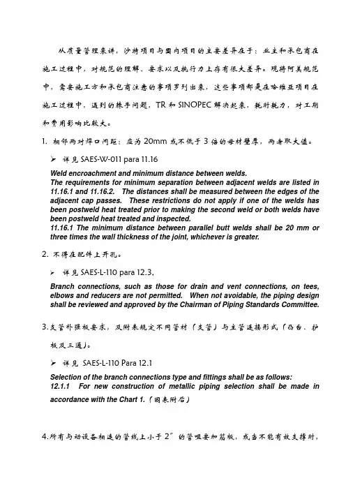
1.相邻两对焊口间距:应为20mm或不低于3倍的母材壁厚,两者取大值。
详见SAES-W-011 para 11.16Weld encroachment and minimum distance between welds.The requirements for minimum separation between adjacent welds are listed in11.16.1 and 11.16.2. The distances shall be measured between the edges of theadjacent cap passes. These restrictions do not apply if one of the welds has been postweld heat treated prior to making the second weld or both welds have been postweld heat treated and inspected.11.16.1 The minimum distance between parallel butt welds shall be 20 mm orthree times the wall thickness of the joint, whichever is greater.2.不得在配件上开孔。
详见SAES-L-110 para 12.3,Branch connections, such as those for drain and vent connections, on tees, elbows and reducers are not permitted. When not avoidable, the piping design shall be reviewed and approved by the Chairman of Piping Standards Committee.3.支管补强板要求,及附表规定不同管材(支管)与主管连接形式(凸台、护板及三通)。
Previous Issue: 19 August 2008 Next Planned Update: 17 July 2017Revised paragraphs are indicated in the right marginPrimary contact: Awami, Luay Hussain on 966-3-880-1341Engineering ProcedureSAEP-102717 July 2012Pressure Relief Valve Conventional and Balanced Types Document Responsibility: Instrumentation Standards CommitteeSaudi Aramco DeskTop StandardsTable of Contents1 Scope (2)2 Applicable Documents (2)3 Detailed Instructions for Saudi AramcoForm 8020-611-ENG (3)4 Responsibilities (14)5 Definition of Terms (14)Next Planned Update: 17 July 2017 Pressure Relief Valve Conventional and Balanced Types1 ScopeSaudi Aramco Engineering Procedures (SAEPs) establish instructions andresponsibilities associated with various engineering activities. This document contains the instructions for entering data into Form 8020-611-ENG, InstrumentationSpecification Sheet, Pressure Relief Valve Conventional and Balanced Types.2 Applicable DocumentsThe requirements contained in the following documents apply to the extent specified in this procedure.2.1 Saudi Aramco DocumentsSaudi Aramco Engineering StandardsSAES-J-600Pressure Relief DevicesSAES-L-140Thermal Expansion Relief in PipingSaudi Aramco Engineering Form8020-611-ENG Instrument Specification Sheet, Pressure ReliefValves- Conventional & Balanced Types2.2 Industry Standards and CodesAmerican Petroleum InstituteAPI RP 520 Sizing, Selection and Installation of Pressure -Relieving Devices in RefineriesAPI RP 526 Flanged Steel Pressure Relief ValvesAmerican Society of Mechanical EngineersASME B31.3 Process PipingASME B31.4 Pipeline Transportation Systems for LiquidHydrocarbons and Other LiquidsASME B31.8 Gas Transmission and Distribution Piping SystemsASME SEC I Rules for Construction of Power BoilersASME SEC VIII Rules for Construction of Pressure ValvesAmerican Society for Testing and MaterialsASTM A216 Standard Specification for Steel Castings, Carbon,Next Planned Update: 17 July 2017 Pressure Relief Valve Conventional and Balanced TypesSuitable for Fusion Welding, for High-Temperature ServiceCrane Co.Technical Paper No. 410 Flow of Fluids through Valves, Fittings, and Pipe 3 Detailed Instructions for Saudi Aramco Form 8020-611-ENGLine 1 Instrument Tag Number for the PZV. This number is found on theP&ID. For new PZV's a new Instrument Tag Number must be assigned.Line 2 Service - Location: Enter the Equipment Number, Line or ProcessSystem the PZV is protecting. On line below specify the service asLiquid, Gas or Vapor.Line 3 Serial Number– The Serial Number of the PZV to be used as a futurereference by the manufacturer to trace all of the original specificationson the PZV.Line 4 P&ID NumberLine 5 Manufacturer - Enter the PZV Manufacturer Name if known.Line 6 Model Number - Enter the PZV Manufacturer's Complete ModelNumber (Vendor to Verify).Line 7 Material Source - Requisition Number (If known, Enter)Line 8 Material Source - SAMS Stock No. (If known, Enter)Line 9 Design Type - (e.g., - Conventional, Balanced Bellows, BalancedBellows w/ Aux. Piston)Line 10 Body Material - Refer to API RP 526 “Flange Safety Relief Valves”and SAES-J-600 materials. Generic Carbon Steel, Stainless Steel, etc., issufficient until the valve is bought, then more detail should be substitutedsuch as (ASTM A216 grade WCB).Line 11 Body Size - Refer to API RP 526 “Flange Safety Relief Valves” forstandard body sizes. (e.g., 4” inlet, 6” outlet, ¾” FNPT inlet, 1” MNPToutlet). F = female and M = male. NPT is National Pipe Thread.Line 12 Body Connection Rating - (e.g., - 300# ANSI Flanged, 3000#Threaded) Refer to API RP526 “Flange Safety Relief Valves” forstandard PZV connection sizes. Per SAES-J-600 minimum inlet flangerating is 300# ANSI.Next Planned Update: 17 July 2017 Pressure Relief Valve Conventional and Balanced Types Line 13 Flange Face Type - (e.g., - RF for Raised Face, RTJ, for Ring Joint, FF - for Flat Faced, N/A if threaded)Line 14 Seat Type - (e.g. - Metal, Soft (O-ring), or manufacturer specific, i.e.,Thermoflex®, Flex-disc®, etc.)Line 15 Bonnet Generally steam service valves are specified with an OPENbonnet to reduce the temperature effects on the spring. All others arenormally CLOSED.With Open Bonnets, the spring is completely visible.A Bellows Valves is normally specified as a Closed Bonnet even thoughit is vented.Line 18 Nozzle and Disc Material - Enter Nozzle and Disc Material.Line 19 Guide Material - Enter the Stem Guide MaterialLine 20 Spring Material - Enter the material of the spring (e.g., - carbon steel,316 S.S., Monel, Hastelloy C, Iconel, Tungsten).Line 21 Spring Coating - (If any - e.g., Nickel Plated, Painted, AluminumMetalized)Line 22 Bellows - Enter the bellows material (e.g., - 316 SS, Monel, 316L SS,Hastelloy Inconel).Line 24 Cap - (This is the cap that covers the setpoint adjustment). Indicatewhether it is Screwed or Bolted. Standard configuration is screwed.Line 25 Lifting Lever - The purpose of the lifting lever is to enable the user toopen the valve when the pressure under the valve disc is lower than theset pressure. The lifting lever is required for Air, Steam and Hot Water.ASME SEC VIII UG-136 (a) (3). The Plain or Open lever assembly isnot pressure-tight and may leak to the atmosphere. Typically used on airand steam applications. Packed levers ensure leakage does not occureither when the valve is open or when backpressure is present.Line 26 Test Gag - The test gag is used to prevent the safety valve from lifting.This is normally only specified for in-place testing of multiple steamvalve installations or where hydrotesting the system is required.Line 27 Vent with Bug Screen - Vents the Bonnet of the PZV. Yes, for Bellows Valves. No, for Conventional Valves.Next Planned Update: 17 July 2017 Pressure Relief Valve Conventional and Balanced Types Line 28 Auxiliary Piston - Auxiliary Balance Piston - Required for Bellowsvalves where a bellows failure may cause an unacceptable increase insetpressure or decrease in flowing capacity from built-up backpressure.Line 29 Liquid Trim - Yes, if the valve is in liquid service. Yes, if the valve isin two-phase flow and greater than 50% of the total MASS flowrate isliquid.Line 31 ASME Code - Choose whether the PZV will be installed as ASME SEC VIII (Pressure Vessels - Stamped UV) or ASME SEC I (Steam Boiler -Stamped V). ASME SEC VIII stamped valves are required for PZVsinstalled on ASME B31.3 “In-plant piping”, ASME B31.4 “LiquidTransport Pipelines”, or ASME B31.8 “ Gas Transmission Pipelines”.Enter “n/a” for relief valves used in service below 15 PSIG such as onAPI 2000 tanks.Line 32 Fire or Blocked Discharge - Choose whether the worst case relievingscenario is either Block Discharge or Fire. If other, then enter n/a and goto Line 33.Line 33 Other - (Basis of Selection), Other than Line 32 worst case relief (e.g., - Thermal Relief, Exchanger Tube Failure, Loss of Reflux, Loss ofCooling Fans, etc.)Line 35 Process Fluid - (e.g., Hydrocarbon, Water, Gasoline, Oil, etc.)Line 36 Corrosive Compounds - Name any significant corrosive compoundssuch as H2S, Sour water, etc.Line 37 Required Capacity - This capacity is given at standard conditions. It is the maximum (worst case) relieving scenario for the basis of selection.Line 38 MW or SG @ Relieving Temperature - The molecular weight of thegas or vapor or the Specific Gravity (referenced to water). The specificgravity is stated at the flowing (relieving) conditions.Line 39 Viscosity @ Relieving Temperature in Centipoise.Line 40 Weight % Flashing / Molecular Weight of the VaporApplicable to liquids only. Flashing liquids require specialconsideration. The correct relief valve size lies between that obtainedfrom the liquid formula and that obtained from the vapor formula,usually closer to the liquid. Flashing probably occurs at the throat,where velocity is sonic. The most reasonable approach is to determineNext Planned Update: 17 July 2017 Pressure Relief Valve Conventional and Balanced Types the liquid portion and the vapor portion separately, compute the arearequired for each quantity, and add them together.Assume an isenthalpic (adiabatic) process.% Flashing = H1-H2 /H LVwhere:H1 = Enthalpy in BTU/lb of saturated liquid at upstream temperature.H2 = Enthalpy in BTU/lb of saturated liquid at downstream pressure.H LV = Latent Heat of Vaporization BTU/lb at downstream pressure.An alternative to the above is to use a process simulation package toperform the flash calculation. Saudi Aramco approved simulationpackages are HYSYS and Pro2 by Simulation Sciences.Balanced Bellows valves may be necessary as a safety precaution whenthe increased downstream PZV body pressure, due to flashing flowconditions, is excessive or cannot be predicted with certainty.Line 41 Temperature at Normal Conditions and at Relief.For Blocked discharge of liquids, the relief temperature is typically thenormal temperature. For blocked discharge of gas on the outlet of acompressor, consider the increased temperature due to the increasedrelieving pressure. For the fire case, the relief temperature of the vaporis the boiling point of the liquid at the relieving pressure.Line 42 Pressure at Normal Conditions and Design Pressure.Design Pressure refers to (at least) the most severe conditions ofcoincident temperature and pressure expected during operation.Design pressure is always equal to or less than the MAWP. Used todetermine the minimum permissible thickness or physical characteristicsof different parts of the vessel. Typically, a corrosion allowance is thenadded to the calculated thickness. If the MAWP is greater than thedesign pressure then this usually means the thickness calculated for thedesign pressure was not commercially available and the next largerrolled plate or pipe was used.Line 43 Set PressureThe set pressure for a single relief valve installation on a vessel orprotected vessel system may not exceed 100% of the MAWP.Next Planned Update: 17 July 2017 Pressure Relief Valve Conventional and Balanced Types Set pressure staggering is allowed for Multiple PZV installations as follows:- First Valve - The maximum allowable set pressure shall not exceed100% of the MAWP- Additional Valve(s) - Set pressures may be staggered but shall notexceed 105% of the MAWP.- Supplemental Valves - (For additional hazard created by exposure tofire or heat). The set pressure shall not exceed 110% of the MAWP.Set pressure shall not exceed 110% for thermal relief valves on piping.(SAES-L-140).Line 44 Constant Superimposed Back-Pressure (See Definition).Line 45 Variable Superimposed Back-Pressure (See Definition).Line 46 Built-up Back-Pressure (See Definition).Line 47 Total Maximum Backpressure = Superimposed plus Built-upbackpressure.Line 48 Cold Differential Test Pressure (CDTP)The cold differential set or test pressure is the actual pressure at which thevalve will open on a test stand. As PZVs are usually set and tested atambient temperature with no backpressure, the CDTP includes anynecessary correction for the actual application, based upon backpressureand / or temperature. Backpressure correction is only needed forConventional PZVs and it addresses constant backpressure only.CDTP (Conventional PZV) = (Set Pressure – Constant SuperimposedBack Pressure) * Temperature Correction Factor.CDTP (Bellows or Pilot PZV) = Set Pressure * Temperature CorrectionFactor.The Pressure adjustment for temperature is specific to the Manufacturerand PZV Model. Consult the manufacturer for discharge temperaturesabove 150°F.Line 49 Net Spring Setting (for Spring Selection)The setting that is adjusted for constant backpressure for conventionalPZVs. This is used for spring range selection.Next Planned Update: 17 July 2017 Pressure Relief Valve Conventional and Balanced TypesLine 50 Accumulation in Percent = (Relieving Pressure - MAWP) / MAWP] *100 Overpressure in PSI = Relieving Pressure – Set PressureExample:Set Pressure = 95 PSIGMAWP = 100 PSIGRelieving Pressure in Vessel = 110 PSIGAccumulation = [(110 -100) / 100] *100 = 10%Overpressure = 110 PSIG - 95 PSIG = 15 PSIGLine 51 Blowdown in Percent = (Set Pressure - P closed) / Set Pressure ) * 100Where P closed = Pressure at which the relief valve closes after openingExample:Setpressure = 100 PSIGRelief Valve Closes at 96 PSIG after opening.Blowdown = [(100 PSIG - 96 PSIG) / 100 PSIG] * 100 = 4%Blowdown should be specified as 2-4% for PZV's in ASME SECI steam service. For other valves 7-9% is generally acceptable.Line 52 Discharges To:Examples:Atmosphere, Grade, Open Funnel, Closed Sewer, Relief Header, FlareHeader, Storage Tank, Pump Suction, etc.Line 53 Maximum Allowable Bellows Back PressureTo prevent damage to, or rupture of, the bellows. This information is tobe supplied by the selected Vendor.Check that the sum of the Superimposed and Built-up Backpressure isnot greater than Line 51.Page 2 – ISS 8020-611-ENGLine 55 Instrument Tag Number - Required on every ISS individual sheet.Line 56 Calculated Maximum Tail Pipe VelocityThis is derived by dividing the Maximum Required Flowrate by thecross-sectional area of the discharge flange. (Ft/Sec) “N/A” if Line 56 isNext Planned Update: 17 July 2017 Pressure Relief Valve Conventional and Balanced Types “N/A”.Line 57 Design Limit on Tail Pipe VelocityRelief System Evaluation for stress on the discharge flare header.For Line 56 choose either Yes or N/A to indicate whether detailed flareheader sound pressure level calculations are required.Input “No” for Line 57 if any of the following items 1-3 are True.1. The PZV does not discharge to a closed system.2. The PZV is for liquid relief.3. The Screening Process indicates obvious safe sound pressure levels.Screening ProcessPerform either Test I, II or III depending on the PZV downstream pipingconfiguration.If the test result is False, then N/A may be entered into Line 57. If thetest results is True, then a Yes is entered into Line 57 to indicate thatfurther downstream piping sound pressure levels are necessary.The calculation sound pressure levels are outside of the scope of the8020-611-ENG specification sheet. The Process Engineering Divisionmay be consulted for help with the detailed sound pressure levelcalculations.Test I - PZV Downstream line size 16 in. and greater:Screening Test: The Mass Flow Rate is greater than91,000 kg/hr (200,000 lb/hr) OR the pressure ratio is greaterthan 3? (True / False)Test II - PZV Downstream line sizes 8 in. to 14 in.Screening Test: The downstream line velocity is greater than50% sonic (0.5 Mach) AND the pressure ratio is greater than 3.(True / False)Test III - PZV Downstream line size less than 8 in. AND is swaged upOR“Teed” to an 8 in. or larger line size.Screening Test: The downstream line velocity is greater than50% sonic (0.5 Mach) AND the pressure ratio is greater than 3.(True / False)Next Planned Update: 17 July 2017 Pressure Relief Valve Conventional and Balanced TypesScreening Process Definitions:Line Velocity = (Maximum PZV Discharge Flowrate)(Cross-sectional area of downstream PZV piping)Sonic Velocity = SQRT (kqRT)(See Crane - “Flow of Fluids” Chapter 1 Equation 1 - 10.)Pressure Ratio = (Built-up Pressure + Normal Flare Header Pressure + 14.7)(Normal Flare Header Pressure + 14.7)Built-up Pressure = See Definitions of TermsLine 58 Calculated Line Piping Pressure LossCalculate the Inlet Pressure drop at the maximum rated relief capacity ofthe PZV. (The stamped rated capacity of the valve).The inlet pressure losses are the accumulative pressure drops due tofriction (as a function of pipe size and length and fluid velocity),entrance and exit losses where they exist, and losses due to valves andfittings. (See Crane “Flow of Fluids” Chapter 1 for more details.)Line 59 Inlet Pressure Loss Limit (3% Set Pressure)Verify that inlet piping pressure loss does not exceed 3% of the setpressure limit (the inlet piping should be as short as possible to minimizethe pressure drop).Inlet Pressure Loss Limit = (Set Pressure * .03)An engineering analysis of the valve performance at higher inlet lossesmay permit increasing the allowable pressure loss above 3%, however,this would require a waiver.Line 63 Spring Range in PSIG (e.g., 80-150 PSIG)This is supplied by the vendor. For existing springs, the range may befound by supplying the stamped part number to Supervisor, OperationsInspection Engineering Unit, Dhahran. Spring selection is based on theCDTP without considering any temperature correction factor.Some manufacturers consider spring Codes and Ranges confidential.Line 64 Manufacturers Spring Number (Manufacturers Part Number)Line 66 Calculated Orifice Area (Square Inches) - Obtained from the APINext Planned Update: 17 July 2017 Pressure Relief Valve Conventional and Balanced Types formulas used on 8020-611-ENG Sheet 3 Lines 98-101.Line 67 Selected API Orifice and Area - The standard effective orifice areasand the corresponding letter designations are listed below as defined byAPI RP 526 Section 3.1 Table 1.Line 68 Actual Orifice Area - This information is the actual orifice area and issupplied by the vendor or may be found in the vendor product literature.Lines 70-73 Multiple Relief ValvesCheck whether multiple valves better serve the application.(SAES-J-600 Paragraph 8.14).Check whether a spare valve is needed for maintenance(SAES-J-600 Paragraph 8.15).Line 70 Set Pressure of Low Valve - (No higher than the MAWP)Exception:Thermal reliefs may be set up to 110% of MAWP per SAES-L-140.Line 71 Set Pressure of Intermediate Valve - (No higher than the 1.05 * MAWP)Next Planned Update: 17 July 2017 Pressure Relief Valve Conventional and Balanced Types Line 72Set Pressure of High Valve - (No higher than the 1.05 * MAWP) Line 73 Set Pressure of Spare Valve - (The Spare Valve is normally set at theset pressure of the low valve.)Page 3 – ISS 8020-611-ENGSheet 3 Note: The Required Orifice Area is to be calculated. Select anappropriate equation. Equation 98 is used for all Gas and VaporCalculations except for a Fire Case on a Dry Gas Filled Vessel, in whichcase Equation 101 is used. Equation 99 is used for all steam PZVs andEquation 100 is used for Certified Liquid Service. Certified means thatthe valve is Code stamped and has liquid trim. See API RP 520 Part Ifor any further clarifications.Line 77Instrument Tag Number - Required on every ISS individual sheet. Line 78 Required Orifice Area (A) in Square Inches - This is the area requiredto flow the worst case relieving scenario. The value A is determined bythe appropriate equation chosen from line 98-101.Commentary Note:For lines 77-95, enter data only for the variables that are specific for thesizing equation selected. All other variable may be left blank.Line 79 Exposed Surface Area of Vessel (A') in Square Feet - For GasExpansion in dry vessels during a fire case only (Line 101). Calculatethe entire surface area of the vessel. (No credit given for insulation).Line 80Specific Heat Coefficient (C) - This factor is used required to calculatethe Valve Factor in Line 79. Table 9 in API RP 520 Part I shows thisvalue as a function of the ratio of specific heats Cp/Cv = k . The value ofC may be calculated directly from the Specific Heat Ratio (k). C k k + k+k -=⎛⎝ ⎫⎭⎪5202111 Example: For Air k = 1.40, C = 356Line 81 Valve Factor (F') ()F CK T T T D '...=-014061112506506ωNext Planned Update: 17 July 2017 Pressure Relief Valve Conventional and Balanced Types Where: Tω= vessel wall temperature, in (°R) andT1= gas temperature, absolute, in (°R), at the upstreampressure, determined from the following relationship:TPPT 11 =ηηWhere: Pη= Normal operating gas pressure, in PSIA andTη= Normal operating gas temperature, in (°R). Line 82 Specific Gravity (G) - The specific gravity of the liquid at the flowing temperature referred to water = 1.00 at 70 °F. Used for liquid sizing. Line 83 Coefficient of Discharge (K D)- This is the effective coefficient of discharge when using the API sizing equations. If the Manufacturer'sactual Coefficient of Discharge is unknown, then use .975 for gas/vaporsizing calculations or .650 for liquid sizing.Line 84 Back Pressure Correction Factor (K b ) - This is the capacitycorrection factor due to back pressure. The back pressure correctionfactor applies to balanced-bellows valves only. K b values can bedetermined from Figure 27 of API RP 520 Part I. (K b = 1 for backpressure less than 30% of the set pressure.)Line 86 Superheated Steam Correction Factor (K SH) - For saturated steam at any pressure, K SH = 1. For Superheated steam, K SH values can bedetermined from Table 10 of API RP 520 Part I.Line 87 Napier Correction Factor (K N) = 1 where P1 < 1515 PSIA.K N = (0.1906P1– 1000) / (0.2292P1– 1061), where P1 > 1515 PSIAand < 3215 PSIA.Line 88 Back Pressure Correction Factor (K W) - This is for balanced-bellows valves in liquid service with back pressure. For atmospheric backpressure, K W = 1. Conventional valves require no special correction.K W values can be determined from Figure 31 of API RP 520 Part I. Line 89 Viscosity Correction Factor (K V) - This is the correction factor due to viscosity. K V values can be determined from Figure 32 of API RP 520Part I.Line 90 Molecular Weight (M) - This is the molecular weight of the gas or vapor. This value should be obtained from the process data.Next Planned Update: 17 July 2017 Pressure Relief Valve Conventional and Balanced Types Line 91 Relieving Pressure (P1) - This is the upstream relieving pressure, inPSIA. It consists of the set pressure (P) plus the allowable overpressureplus atmospheric pressure.Line 92 Set Pressure (P) - See the definition of set pressure.Line 93 Back Pressure (P b) - See the definition of back pressure.Line 94 Relieving Temperature (T) - This is the relieving temperature of theinlet gas or vapor in °R. (Degrees Rankine = Degrees Fahrenheit +459.67).Line 95 Liquid Flow (Q) - This is the flow rate at the flowing temperature, inU.S. gallons per minute (GPM).Line 96 Gas/Vapor/Steam Flow (W) - This is the required flow through thevalve, in pounds per hour (LB/HR).Line 97 Compressibility Factor (Z) - This is the compressibility factor for thedeviation of the actual gas from a perfect gas, a ratio evaluated at inletconditions.Lines 98-101 Area EquationsSelect the appropriate equation. Write the equation vertically in thespace provided showing the value for each variable and the resultantcalculated area. For Electronically filled in sheets, it is permissible toshow the end calculation result.4 Responsibilities4.1 Instrumentation UnitThe Instrumentation Unit is responsible for keeping this document and theISS Form 8020-611-ENG current and accurate.4.2 Originating EngineerIt is the responsibility of the Originating Engineer to complete ISS Form8020-611-ENG for conventional and bellows operated relief valves before thePZV is entered into the Relief Valve Program for testing and inspection.5 Definition of TermsAccumulation: the pressure increase in the vessel over the maximum allowableworking pressure with the valve, or valves, open and at required relieving capacity; it isNext Planned Update: 17 July 2017 Pressure Relief Valve Conventional and Balanced Types expressed as a percentage of Maximum Allowable Working Pressure, or in kPa(ga) or(psig). The permissible accumulation for various conditions is specified in the ASMECodes.Commentary Note:Accumulation is the same as overpressure when the PZV is set at the MaximumAllowable Working Pressure of the vessel.Back Pressure: the pressure on the discharge side of a relief valve. Different types of back pressures are:a) Superimposed Back Pressure: the pressure on the discharge side of a reliefvalve, against which the valve must begin to open. It may be constant or variable.b) Built-up Back Pressure: the pressure on the discharge side of a relief valvedeveloped as a result of flow due to the valve in question relieving into thedischarge header system. Where multiple valves relieve under a singlecontingency, the back pressure increase in the discharge system as a result of allinvolved valves relieving, determines the built up back pressure.Built-up Back Pressure is calculated by adding all of the discharge header pressuredrops. The pressure losses are the accumulative pressure drops due to friction (asa function of pipe size and length and fluid velocity), entrance and exit losseswhere they exist, and losses due to valves and fittings. (See Crane “TechnicalPaper No. 410” Chapter 1 for more details.)Built-up back pressure may be taken as zero for PZV's that discharge toatmosphere through a full size elbow and short discharge pipe leg.Balanced Safety Relief Valve: a pressure relief valve which incorporates means ofminimizing the effect of back pressure on the operational characteristics (openingpressure, closing pressure, and relieving capacity).Blowdown: the difference between the set pressure and the resetting pressure of arelief valve, expressed as a percentage of the set pressure or in kPa (psig).“Cold” Differential Test Pressure: the pressure in kPa (psig) at which a relief valve is adjusted to open on the test stand. This pressure includes the correction for maximumsuperimposed back pressure (for conventional non-bellows valve only) and/ortemperature service conditions.Conventional Safety Relief Valve: a pressure relief valve which has its spring housing vented to the discharge side of the valve. The operational characteristics (openingpressure, closing pressure, and relieving capacity) are directly affected by changes ofthe back pressure on the valves.Next Planned Update: 17 July 2017 Pressure Relief Valve Conventional and Balanced Types Design Pressure: the pressure, exclusive of any static heads, used to determine theminimum permissible thickness or physical characteristics of the different parts of thevessel.Disc: the pressure containing movable element of a pressure relief valve which effects closure.Lift: the amount the disc rises above the seat in pressure relief valves.Maximum Allowable Working Pressure (MAWP): the maximum pressure in kPa(psig) permissible at the top of a completed vessel in its operating position for adesignated temperature. It is the highest pressure at which a relief valve may be set tobegin to open.Nozzle: a pressure containing element which constitutes the inlet flow passage andincludes the fixed portion of the seat closure.Operating Pressure: the pressure at the top of a pressure vessel at which the vesselsnormally operates.Overpressure: the pressure increase over the set pressure of the primary relief valve.It is the same as accumulation when the relief valve is set at the maximum allowableworking pressure of the vessel.Rated Capacity: the percentage of measured flow at an authorized percentoverpressure permitted by the applicable code. Rated capacity is generally expressed in pounds per hour (lbs/hr) for vapors; standard cubic feet per minute (SCFM) for gases;and in gallons per minute (GPM) for liquids.Relief Valve: an automatic pressure-relieving device actuated by the static pressureupstream of the valve, and which opens in proportion to the increase in pressure above set pressure. It is used primarily for liquid service.Commentary Note:For the sake of simplicity all pressure relief devices (valves) referred to in this procedureare called “PZV”.Relieving Pressure: the pressure in the protected vessel with the relieving devices full open. It is the set pressure plus the actual overpressure. Relief valves shall be sized to prevent the relieving pressure from exceeding the Maximum Allowable WorkingPressure plus the allowable accumulation.Safety Relief Valve: an automatic pressure-relieving device suitable for use as either a safety or relief valve. It is used in gas or vapor service or for liquid.。
Previous Issue: 29 October 2003 Next Planned Update: 27 April 2014 Revised paragraphs are indicated in the right marginPage 1 of 6Primary contact: Kakpovbia, Anthony E. on 966-3-8747226Engineering ProcedureSAEP-1107 27 April 2009 Welding Test Supplement S07 for GTAW, Carbon, Low Alloy and Stainless Steel PipeInspection Engineering Standards Committee MembersKakpovbia, Anthony Eyankwiere, Chairman Rajeh, Saleh Rashid, Vice Chairman Stockenberger, Hans J Mc Ghee, Patrick Timothy Khunaizi, Mohammad Redhi Suwaidan, Khalid AliSeyed Mohamed, Abdul Cader Boult, David Carrera, R LLangla, Edward Charles Ingram, James Young Keen, Peter David Ghamdi, Khalid Salem Albarillo, Rodolfo Celino Anazy, Khalid JumaShammary, Hamed Abdulwahab Mohsen, Hassan AbdallahSaudi Aramco DeskTop StandardsTable of Contents1 Scope............................................................ 2 2 Applicable Documents................................... 2 3 Instructions. (2)Next Planned Update: 27 April 2014 Carbon, Low Alloy and Stainless Steel Pipe 1 ScopeThis welder performance qualification Test Supplement shall govern the testing ofwelders with the Gas Tungsten Arc Welding (GTAW) process, welding progressionvertical up, for welding carbon, low alloy and stainless steel pipe.2 Applicable DocumentsThe requirements contained in the following documents apply to the extent specified in this procedure.2.1 Saudi Aramco ReferencesSaudi Aramco Engineering ProceduresSAEP-321 Performance Qualification Testing andCertification of Saudi Aramco WeldersSAEP-1101 Welding Test Supplement S01 for SMAW, Carbonand Low Alloy Steel PipeSAEP-1103 Welding Test Supplement S03 for SMAW,Stainless Steel, Single SidedSAEP-1104 Welding Test Supplement S04 for SMAW,Stainless Steel/Nickel, Backing2.2 Industry Code(s) and Standard(s)American Society of Mechanical EngineersASME SEC IX Qualification Standard for Welding and BrazingProcedures, Welders, Brazers, and Weldingand Brazing Operators3 InstructionsConduct the Performance qualification testing of welders following the requirements of SAEP-321 as supplemented by the subsequent instructions.3.1 ApplicationsPiping YesPipelines YesPressure Vessels NoTanks NoNext Planned Update: 27 April 2014 Carbon, Low Alloy and Stainless Steel PipeStructural NoDissimilar Metals Yes ** See restrictions in paragraph 3.93.7 Testing and Inspection RequirementsTime Limit of Test Two (2) hours maximumRadiography 100% (ASME QW-191)Visual Inspection See paragraph 6.1.3 of SAEP-3213.8 Qualification LimitsMaterial Form Plate or pipeJoint Type Groove welds with and without backing, and filletweldsBase Material Carbon steels (P1), low alloy steels (P3, P4, P5,P9, P11), stainless steels (P8) only to themselves,and carbon & low alloy steels to each other.Process GTAWFiller Metal (Root/Fill/Cap):Carbon Steel ERXXS-X (A5.18)Low Alloy Steel ERXX(X)S-X(X) (A5.28)Stainless Steel ERXXX (A5.9)Gas Backing Inert gas backing is required when welding P5materials (and materials with greater P-Numbers)to themselves or to each otherBase Metal Thickness 0.436" maximumDiameter Range 1" NPS and greater with no restrictions. For theoccasional job requiring welding of butt joints lessthan one inch (1") diameter, the welder shall welda 2G and 5G test coupon on the smallest job sizediameter tubing. The welding shall be witnessedby the OIU inspector and the weld radiographed.Both test coupons shall meet the acceptancecriteria of paragraph 3.7 of this Test Supplement.Next Planned Update: 27 April 2014 Carbon, Low Alloy and Stainless Steel PipeAcceptance shall qualify the welder to weld tubingdiameters between one inch (1") and the diametertested, and shall remain in effect as long as thewelder welds tubing in the diameter rangecontinuously and up until one month afterwards.Positions AllVertical Progression Uphill3.9 RestrictionsDissimilar Metal Welds (between ferritic steels and austenitic stainless steelsmade with ER309 GTAW filler metals only) are permitted for:1) Structural welding applications where welds are not in contact with servicefluid and the design temperature is less than 300°C, and2) The welding of stainless steel name plates to pressure vessel shells.Revision Summary27 April 2009 Revised the "Next Planned Update". Reaffirmed the contents of the document and reissiedwith editorial change.Next Planned Update: 27 April 2014 Carbon, Low Alloy and Stainless Steel PipeNext Planned Update: 27 April 2014 Carbon, Low Alloy and Stainless Steel PipeWELD LAYER PROCESSRoot GTAWHot GTAWFill GTAWCap GTAW。
Engineering StandardSAES-P-111 28 January, 2004 GroundingElectrical Standards Committee MembersAl-Anizi, T.S., ChairmanAl-Abdulgader, A.A.Al-Ahmad, R.J.Al-Awdah, S.A.Carlson, R.W.Ismail, M.H.Lowe, J.Merbati, F.A.Moravsik, R.C.Refaee, J.A.Stansbury, M.C.Saudi Aramco DeskTop StandardsTable of Contents1 Scope (2)2 Conflicts, Deviations, and Commentary (2)3 References (2)4 General (4)5 Materials and Installation (6)6 Substation Grounding (9)7 Grounding Electrodes (9)8 System Grounding (10)9 Equipment Grounding (12)10 Offshore Platform Grounding (16)11 Fence Grounding (16)12 Tank Grounding (18)13 Lightning Protection (18)14 Static Electricity Grounding (18)1 ScopeThis standard prescribes minimum mandatory requirements for design and installation of grounding systems and lightning protection systems for Saudi Aramco facilities. This document may not be Previous Issue: 30 November, 2003 Next Planned Update: 1 October, 2008Next Planned Update: 1 October, 2008 Grounding attached to nor made a part of purchase orders.2 Conflicts, Deviations, and Commentary2.1 If there are any conflicts between this Standard and associated purchasing, project orengineering documents, this standard shall take precedence. The exception is if an approvedWaiver form SA 6409-ENG has been included with the purchasing documents.2.2 Any conflicts between this standard and other applicable Saudi Aramco EngineeringStandards (SAESs), Materials System Specifications (SAMSSs), Standard Drawings(SASDs), or industry standards, codes, and forms shall be resolved in writing by the companyor buyer representative through the Manager, Consulting Services Department of SaudiAramco, Dhahran.2.3 Direct all requests to deviate from this standard in writing to the company or buyerrepresentative, who shall follow internal company procedure SAEP-302 and forward suchrequests to the Manager, Consulting Services Department of Saudi Aramco, Dhahran.2.4 The designation "Commentary" is used to label a sub-paragraph that contains comments thatare explanatory or advisory. These comments are not mandatory, except to the extent thatthey explain mandatory requirements contained in this SAES.3 ReferencesThe selection of material and equipment, and the design, construction, maintenance, and repair of equipment and facilities covered by this standard shall comply with the latest edition of the references listed below, unless otherwise noted.3.1 Saudi Aramco ReferencesSaudi Aramco Engineering ProcedureSAEP-302 Instructions for Obtaining a Waiver of a Mandatory SaudiAramco Engineering RequirementSaudi Aramco Engineering StandardsSAES-B-070 Bulk PlantsSAES-M-006 Saudi Aramco Security and General Purpose FencingSAES-J-902 Electrical Systems for InstrumentationSAES-P-100 Basic Power System Design CriteriaSAES-P-104 Wiring Methods and MaterialsSAES-P-107 Overhead Distribution SystemsSAES-T Series Communications Engineering StandardsSAES-X-400 Cathodic Protection of Buried PipelinesSaudi Aramco Materials System SpecificationNext Planned Update: 1 October, 2008 Grounding 15-SAMSS-502 Medium Voltage Power Cables 5 kV though 35 kVSaudi Aramco Library DrawingDD-950022 Grounding Connections Details Ground Rod to GroundGridSaudi Aramco Standard DrawingsAB-036387 Tank GroundingAA-036572 Grounding Arrangement for Disconnect Switch Structure3.2 Industry Codes and StandardsAmerican National Standards InstituteANSI C2 National Electrical Safety CodeAmerican Petroleum InstituteAPI RP 2003 Protection Against Ignitions Arising out of Static,Lightning, and Stray CurrentsInstitute of Electrical and Electronics EngineersIEEE 80 Guide for Safety in Alternating-Current SubstationGroundingIEEE 81 Guide for Measuring Earth Resistivity, Ground Impedance,and Earth Surface Potentials of a Ground System IEEE 142 Recommended Practice for Grounding of Industrial andCommercial Power SystemsIEEE 399 IEEE Recommended Practice for Power Systems Analysis(Brown Book)IEEE 1100 Powering and Grounding Sensitive Electronic Equipment International Electrotechnical CommissionIEC 61662 Assessment of Risk of Damage Due to LightningIEC 61024-1 Protection of Structures Against LightningIEC 61024-1-1 Protection of Structures Against Lightning Part 1:General Principles Section 1: Guide A – Selection ofProtection Levels for Lightning Protection Systems National Fire Protection AssociationNFPA 70 National Electrical CodeNFPA 99 Health Care FacilitiesNFPA 780 Lightning Protection CodeNext Planned Update: 1 October, 2008 GroundingUnderwriters LaboratoriesUL 96 Lightning Protection ComponentsUL 96A Installation Requirements for Lightning ProtectionSystemsUL 467 Grounding and Bonding Equipment4 General4.1 Except as noted in 4.2, grounding and ground system installation shall be designed inaccordance with IEEE 142 and meet the requirements of ANSI/NFPA 70 (NEC), and ANSIC2, as supplemented or amended by this Standard. Requirements for specific facilities are asfollows:a) Health Care Facility grounding shall meet additional requirements ofNFPA 99;b) Communications System grounding shall be in accordance with theSAES-T Series;c) SAES-J-902 shall take precedence over this standard for grounding of process controlinstrumentation and process control systems. Refer to SAES-J-902 for groundingsensitive electronic equipment associated with process control systems.Commentary Notes 4.1:It is intended that the terminology used in this standard be consistent with the NEC.Sensitive electronic equipment not covered by SAES-J-902 should be grounded inaccordance with the recommendations of IEEE 1100.4.2 Except as specifically noted, electrical installations in residential facilities, recreationalfacilities, schools and office buildings (including office buildings associated with plants andindustrial facilities) shall be grounded in accordance with the industry standards referenced in4.1 and are not required to meet the additional requirements contained in this standard.4.3 Measurements of earth resistivity and ground impedance shall be made in accordance withIEEE 81 or by a non-contacting ground resistivity mapping instrument (Geonics or equal). Insoils exceeding 5000 ohm-cm. the measurements shall be taken or verified by anon-contacting ground resistivity-mapping instrument.Commentary Note 4.3:Special techniques may be needed to avoid errors in measuring earth resistivity inareas congested with existing grounding systems, existing cathodic protectionsystems, and/or existing underground metal structures.4.4 Calculations of allowable and actual step and touch potentials shall be done in accordancewith IEEE 80 using the following parameters:4.4.1 A body weight of 50 kg shall be assumed.Next Planned Update: 1 October, 2008 Grounding4.4.2 Duration of ground faults used in calculations for maximum allowable step andtouch potential shall be the time (based on known operating conditions) it would takefor the backup breaker to clear the fault with a minimum of 0.25 sec. and a maximumof 1.0 sec.4.4.3 Ground fault current shall be the higher of the line to line to ground or thesymmetrical line to ground fault current.4.4.4 In calculations of the grid current, the current division factor must be assumed to be1.0 unless calculations based on known actual site conditions are provided to justifya lower number.Commentary 4.4.4:The current division factor is used to account for the current that returns tothe source though an overhead ground wire rather than through thesubstation ground grid and earth.4.4.5 For calculations of allowable step and touch potentials, the resistivity of the surfacematerial (rho sub s) shall be assumed to be 3,000 ohm-meters for a minimum 75 mmthick pad of clean crushed rock, 10,000 ohm-meters for a minimum 50 mm layer ofasphalt, and 200 ohm-meters for a minimum 75 mm layer of concrete. For all othersurface materials, the lower of 100 ohm-meters or the actual measured top layer(minimum 0.3 m layer thickness) soil resistivity shall be used.4.4.6 Calculations of mesh voltage and ground potential rise (See IEEE 80) shall be basedon actual measured soil resistivity. If native material is replaced by fill, calculationsshall incorporate the effect of the measured soil resistivity of the fill.Commentary Note 4.4.6:IEEE 399 "IEEE Recommended Practice for Power Systems Analysis(Brown Book) provides additional information on analysis of ground gridsfor substations. The techniques covered in IEEE 80 are most useful foranalyzing and designing ground grids for substations connected to solidlygrounded high voltage lines. The guidance in NEC and this standard willbe most useful in other portions of the electrical system.4.5 Soil resistivity of backfill material used for ground grids and ground rods shall be the same asor less than that of the surrounding soil.4.6 Commissioning tests shall be performed to verify that resistance to remote earth of substationground grids and/or ground electrodes used for system grounding meet design requirements.5 Materials and InstallationThis section also applies to electrical installations in residential facilities, recreational facilities and office buildings.5.1 Conductors used as grid conductors, grounding electrode conductors, equipment groundconductors, or bonding conductors in grounding systems shall:Next Planned Update: 1 October, 2008 Groundinga) Be soft or annealed copper.b) If larger than 35 mm² (#2 AWG) be stranded. Stranding of ground conductors shallcomply with the stranding requirements of SAES-P-104.c) Except for grid conductors used in substations for potential control purposes beinsulated when used in direct contact with soil less than 70 ohm-meters resistivity.d) If used for grid conductors in substations for potential control purposes be bare and ifused in soils less than 70 ohm-meters resistivity be tinned.e) If insulated have a green jacket or a green jacket with yellow stripes. When isolatedground equipment grounding conductors are installed per IEEE 1100, they must belabeled or color coded to distinguish them from standard equipment groundingconductors.f) If exposed above grade in a severe corrosion area (as defined inSAES-P-104) be insulated.g) If buried and used for grids and/or interconnection of ground rods be minimum 70 mm²(2/0 AWG).h) If used for connection of equipment to ground rods or ground grid be minimum 25mm² (#4 AWG).Exception 5.1:See SAES-P-107 for pole ground wires.Commentary Note 5.1:Soils in Saudi Aramco areas which are lower than 70 ohm-meters resistivitynormally have high salt content and are corrosive to copper. In areas wherecathodic protection is present, galvanized steel ground rods are recommended.Where insulated ground conductors are used, enough ground rods must be used toachieve the specified ground resistance. Insulated ground conductors are notsuitable for use in substation ground grids to mitigate high levels of groundpotential rise.5.2 Ground rods shall have the following characteristics:a) Be copper or copper jacketed steel or galvanized steel. Copper jacketed steel("Copperweld" or equivalent) shall meet the requirements of UL 467.b) If galvanized steel, only be used in areas protected by cathodic protection.c) Have a minimum length of 2.4 meters. Jointed rods are permitted but each joint mustbe at least 2.4 meters long.d) For copper or copper jacketed steel rods be a minimum of 16 mm in diameter and forgalvanized steel rods be a minimum of 19 mm in diameter.e) When grounding is required at pipeline valve stations, zinc or magnesium anodesinterconnected with insulated copper cable may be used in lieu of copper clad orgalvanized steel ground rods. Each required ground rod shall be replaced with a zinc ormagnesium anode and a minimum of two zinc or magnesium anodes spaced a minimumof 2 meters apart shall be installed. Installation of the anodes shall be in accordance withNext Planned Update: 1 October, 2008 Grounding SAES-X-400.Commentary Note 5.2 e):Buried bare copper has a detrimental effect on pipeline cathodic protection.5.3 Below ground connections to grounding grids and ground rods or between conductors and/orgrounding rods shall be made using one of the following methods:a) By thermite welding or brazing.b) By approved compression grounding connectors.c) For connections at ground test stations only where it is necessary to disconnect groundconductors for tests, approved mechanical connectors may be used.Commentary Note 5.3:Library Drawing DD-950022 shows recommended details for making groundingconnections.5.4 Above ground grounding system connections shall be made by one of the following:a) In accordance with the NEC as supplemented by SAES-P-104.b) By thermite welding or brazing.c) To structural steel using compression type connectors bolted to bare steel, by thermitewelding, or by other approved means.5.5 Grounding conductors which do not accompany associated power conductors in the sameconduit shall not be installed in metallic conduit except where PVC conduit is not suitable andit is necessary to protect the conductor from mechanical damage. Grounding conductorsinstalled in metallic conduit or sleeves that do not accompany associated power conductorsshall be bonded to both ends of the conduit.5.6 Grounding conductors extending through concrete or asphalt shall be run in PVC conduit(preferred) or PVC coated rigid steel conduit. Grounding conductors in steel conduit shall bebonded as noted in Paragraph 5.5.5.7 Underground ground conductors shall be insulated when within 3 meters of a buried metalpipeline or metal piping.5.8 Underground ground conductors electrically connected to buried metal pipelines, buriedmetal vessels, or metal tanks sitting on grade shall be insulated. The associated ground rodsshall be galvanized steel if the area is subject to cathodic protection.6 Substation Grounding6.1 For substations having equipment operating at a nominal system voltage exceeding 1,000Volts, a ground grid meeting the requirements of IEEE 80 for step and touch potential shall beinstalled. Design for the substation grid and the associated overall plant grounding systemshall account for hazards due to transferred potentials caused by a fault in the substation. AllNext Planned Update: 1 October, 2008 Grounding electrical equipment in the substation, substation yard, and within 5 meters of the substationfence shall be connected to the grid or to a ground bus connected to the grid.Commentary Note 6.1:See IEEE 80 For Discussion of Transferred Potentials.6.2 The design package for ground grids and systems for substations with equipment operating atabove 15 kV shall be submitted to the Coordinator, Electrical Systems Division, ConsultingServices Department for review.6.3 Substation ground grids shall be constructed of minimum 70 mm² (2/0 AWG) stranded barecopper cable.7 Grounding Electrodes7.1 Grounding electrode systems, including those for residential facilities, recreational facilities,schools, and office buildings, shall be in accordance with the NEC with the followingadditions:7.1.1 Reinforcing bar of buildings shall not be used as a grounding electrode. Structuralsteel of a building may be used as a grounding electrode in accordance with the NECprovided it is continuous and effectively grounded by connecting at least every otherstructural steel column on the perimeter of the building to a concrete-encasedelectrode or a ground ring installed per the NEC and this standard.7.1.2 If a concrete-encased electrode is used, the conductor must be bare copper.7.1.3 The ground electrode for system grounding shall consist of either (1) rod or pipeelectrode(s), or (2) a combination of rod or pipe electrodes and a grid or loop of barecopper conductors buried a minimum of 460 mm. Multiple rod or pipe electrodesshall be interconnected by bare or insulated copper conductors using thermitewelding or approved connectors per 5.3. Conductors used to interconnect rod or pipeelectrodes shall be buried a minimum of 460 mm.Commentary Note 7.1.3:Minimum conductor burial depth and length requirements of the NEC areapplicable for "Ground Rings" encircling a building or structure thatconstitutes the only made electrode for the building. Minimum burial depthrequirements of this paragraph apply to conductors (bare or covered) usedto interconnect rods or other made electrodes.7.2 Supplementary grounding electrodes per NEC 250-54 shall be provided in outdoor industrialareas, process plant areas, and in substations not covered by Paragraph 6.1. In areas where noelectrical equipment is installed, this supplementary grounding is not required unlessotherwise specified. Supplementary electrodes shall consist of ground rods connected bybare or covered conductors, bare ground conductors, or combinations. Resistance to groundof each supplementary grounding electrode system shall meet the minimum requirements ofNEC Article 250-56 for made electrodes. Where multiple items of equipment are connected,the supplementary grounding electrodes shall be interconnected using bare or insulatedNext Planned Update: 1 October, 2008 Grounding conductors to form grids or loops. The grids or loops shall be buried a minimum of 460 mm.This grounding electrode shall be bonded to the equipment grounding system in the area andmay constitute a made electrode required to meet NEC requirements.7.3 If an above ground bus or loop is used for extending the supplementary electrode, this bus orloop shall have two connections to the supplementary electrode.8 System Grounding8.1 Three-phase electrical systems shall be grounded at the neutral point of the wye-connectedwindings of the transformers or generators and connected as directly as possible to the grid orgrounding electrode. The system grounding connections shall be made directly to thegrounding electrode and be routed separately from equipment grounding connections.Exceptions:Three-phase 120/208 V systems fed from a transformer with a primary voltage lessthan 600 V shall be grounded in accordance with NEC rules for separately derivedsystems.Dry-type lighting or building service transformers in substations, in switchgearrooms, or in equipment rooms may be connected to a ground bus that is directlyconnected to the grid or other grounding electrode.8.2The type of system grounding shall be selected per Table 1.Table 1 – System GroundingNotes:1. High resistance grounding for 480 V systems is permitted with approval of the Electrical StandardsCommittee Chairman.2. Selection of rating for 13,800 V system grounding resistor shall be done by or with the concurrence ofCoordinator, Relay & Operations Engineering Division, Power Distribution Department.3. See SAES-P-100 for approval requirements for extension of ungrounded systems.4. Except as noted systems originate from wye connected transformer secondary.Next Planned Update: 1 October, 2008 Grounding8.3 The ground resistance of made electrodes (ground rods and/or ground grid) used for systemgrounding shall not exceed 1 ohm for solidly grounded systems above 600 V, 5 ohms forresistance grounded systems above 600V and 5 ohms for systems under 600 V. In all casesstep and touch potentials during ground faults shall not exceed the safe values defined inIEEE 80.8.4 All grounding electrodes used for system grounding in plants, bulk distribution facilities, orother industrial areas shall be interconnected to form a single ground system. The groundingelectrode used for system grounding (including separately derived systems) for each area inthe facility or plant shall have a minimum of two connections to the ground grid or groundloop used in the area. This requirement can be met by connections to the grounding electrodeof the substation(s) which supply the area.8.5 The secondary of dedicated (captive) transformers supplying electric submersible pumps inwater or oil well service are permitted to be ungrounded providing that the motor controllerhas ground fault detection and the transformer is located at the same well site as the pumpserved.Commentary Note 8.5:Ungrounded supply from captive transformers for electric submersible pumps isrecommended.8.6the proponent and the approval of the Electrical Standards Committee Chairman.8.6.1 High resistance grounding is only permitted in plants and bulk distribution facilitieswhere full time maintenance or operations personnel are available and capable ofresponding to, and isolating, a ground fault within one hour of an alarm. Equipmentfor rapid location of ground faults must be provided as part of the high resistancegrounding system. Additionally, relays capable of quickly sensing and isolating asecond ground fault shall be provided.8.6.2 Two hundred seventy seven (277) VAC neutral loads are not permitted.8.6.3 When requesting approval for high resistance grounding systems, the following mustbe submitted:∙Details of ground fault alarm system,∙details of the fault locating apparatus,∙details of the protection scheme,∙calculations or measurements for selection of grounding resistor, and∙concurrence of the proponent that the level of response to ground faults requiredby paragraph 8.6.1 will be provided.9 Equipment Grounding9.1 Except as otherwise noted below, conduit, cable tray, or cable armor, shall not be relied on asNext Planned Update: 1 October, 2008 Grounding the equipment grounding conductor and a bare or insulated copper conductor shall beinstalled in the same conduit, cable tray, cable, or cord or shall otherwise accompany thepower conductors. Regardless of whether this standard permits conduit, cable tray or cablearmor to be relied on as the equipment grounding conductor the conduit, cable tray, or cablearmor installations must meet NEC bonding and grounding requirements for such use. Inhazardous locations equipment grounding conductors run in conduit or cable tray shall beinsulated or enclosed within the jacket of a multi-conductor cable.Exceptions:Conduit or cable armor may be used in accordance with the NEC for groundingelectronic instrumentation operating at 24 V DC nominal or below.Cable armor, if properly sized and terminated with cable terminators that areapproved for grounding purposes may be used for equipment grounding inaccordance with the NEC (cable armor must be a type that is specifically permittedby the NEC for such use) provided the cable runs in one continuous length (nosplices or intervening junction boxes are permitted) from the substation orequipment controller to the equipment being grounded and the cable is not in directcontact with the soil for any portion of the run. Repairs to existing cable meetingthe requirements are permitted provided armor of the two sections is properlybonded.Commentary Note 9.1:In accordance with the NEC an equipment grounding conductor is not requiredbetween the neutral point of a transformer and a service disconnecting means.The grounded circuit conductor (neutral) required by the NEC is sufficient. SeeNEC Article 250-142.9.1.1 Aluminum cable trays containing only circuits operated at, or below, 50 V to groundmay be used as equipment grounding conductors provided that NEC requirementsfor such use are met. On other aluminum cable trays, a common equipmentgrounding conductor external to the cables in the tray may be used under thefollowing conditions:∙This common conductor shall be sized in accordance with NEC Table 250-122for the largest power conductor in the tray, with a minimum size of 25 mm² (#4AWG).∙Connections shall be made between this common grounding conductor andother grounding conductors for intersecting or branch trays, and to extend theequipment grounding conductor beyond the tray.∙This common conductor (or the largest individual grounding conductor, if morethan one are installed) shall be bonded to each section of the cable tray systemwith a connector approved for a copper to aluminum connection.9.1.2 A cable concentric neutral, if properly sized and not used as a current carryinggrounded circuit conductor (3 phase 3 wire system; no neutral loads are served), maybe used as the equipment grounding conductor.Next Planned Update: 1 October, 2008 Grounding Commentary Note:The cable must meet the requirements of 15-SAMSS-502 that requires anoverall jacket to protect the concentric neutral.9.1.3 Electrical submersible pump motors in oil and water well service do not require adedicated equipment grounding conductor, provided the motor controller has groundfault detection. The well head must be bonded by an approved means to the groundbus at the motor controller or supply transformer.9.1.4 Armored submarine cables do not require equipment grounding conductors.9.2 Shields and armor of power cable shall be grounded at both ends. Continuity at splices shallbe maintained by bonding across the splice.Commentary 9.2:Installation of voltage limiters may be necessary if cable shields and armor are notgrounded at both ends.9.3 Metallic conduit shall be grounded at both end points by bonding to a grounding conductor, agrounded metal enclosure, or to a grounded metal cable tray. This may be accomplished:∙with approved grounding clamps and conductors connected externally to the conduit or∙by bonding to a grounded enclosure using integral threaded bushings or using a conduit hub (15-287-xxx or equal) which is approved for grounding purposes or∙bonding to a grounding conductor using an approved grounding bushing (15-287-409 or similar). Grounding with locknuts is not acceptable. or∙where non-PVC coated rigid conduit is used to protect cable entering or exiting a grounded metal cable tray, by bonding with a conduit clamp to the cable tray. Agrounding bushing must be used with PVC coated conduit.Exceptions 9.3:Where EMT is permitted it may be grounded and bonded using any meansaccepted by the NEC.Isolated sections of rigid metal conduit that are buried at all points at least 0.5meters below grade are not required to be grounded. (e.g., Conduit sleeves forroad crossings.)Conduit sleeves used to enclose power cables transitioning from above grade tobelow grade are required to be grounded only at the above grade end.9.4 Metallic cable trays shall be bonded at both end points and a minimum of every25 m to the local ground grid or ground electrode or to structural steel which is bonded to thelocal ground grid or ground electrode.9.5 Ground busses in switchgear, switchboards, and motor control centers shall have two。
最新沙特阿美构建质量管理体系最新沙特阿美构建质量管理体系沙特阿美对工程项目的质量管理工作是质量控制(QC)。
下面是店铺为大家分享最新沙特阿美构建质量管理体系,欢迎大家阅读浏览。
1 沙特阿美质量管理体系的构成沙特阿美的质量管理体系是一个庞大的系统,其核心是组织过程资产,包括公司标准、材料规范、程序文件、管理手册、QMIS系统等,与工程质量管理有关的机构主要包括PID(项目检验部)、PMT(项目管理团队)和VID(供货商检验部)等。
QMIS为沙特阿美质量管理信息系统,是整个管理体系运行的平台,发挥着重要的作用。
PID是专门的工程质量检验机构,其下属的专业工程师并不专门服务于某一个项目,而是负责多个项目,严格按照规范标准和程序文件的要求对工程进行监督管理。
PMT专门负责一个项目,以业主代表的身份,对特定项目进行包括质量管理在内的全面管理。
VID主要进行供货商管理,不参与具体项目的管理,对沙特阿美批准的供货商进行宏观管理,从源头上确保材料采购质量。
沙特阿美没有“国家标准”,执行地面工程项目的主要依据是沙特阿美工程标准(SAES)、材料规范(SAMSS)和项目程序文件(SAEP)。
这些标准严格程度与美国标准或国际标准相当,文件数量达700多个,覆盖所有的工程领域,使任何一项施工活动都有据可查。
为避免在不同文件中出现相同内容,采用引用跳转而不是重复表述的方式,确保口径一致,防止文件冲突。
在某些专业领域,也适当引用国际标准或美国标准作补充。
标准每四年更新一次,在标准的任何一页的页眉,都会标注此标准的发布日期及下一次更新日期,提醒发布者和使用者及时更新。
沙特阿美标准是技术标准,而程序文件则是管理标准,用于指导检验、试验、评估、验收、文件编制等活动,每五年更新一次。
2 沙特阿美质量管理体系运行模式2.1 沙特阿美对承包商的质量管理作为业主,沙特阿美质量管理工作的重点是质量保证(QA)。
沙特阿美对大部分工程项目、物资材料实行国际公开招标和采购,每年招标合同额约为200亿美元,管理的承包商和供货商不计其数。
Engineering ProcedureSAEP-125 15 October 2008 Preparation of Saudi Aramco Engineering StandardsDocument Responsibility: Standards CoordinatorSaudi Aramco DeskTop StandardsTable of ContentsScope (2)1ApplicableDocuments (2)2Instructions (2)3Responsibilities (6)4Attachment I – Exception StyleSaudi Aramco Engineering Standard (7)Attachment II – Narrative StyleSaudi Aramco Engineering Standard (9)Previous Issue: 31 May 2003 Next Planned Update: 15 October 2013Revised paragraphs are indicated in the right margin Page 1 of 9 Primary contact: Ghulam, Ziad Mohammad Jamil on 966-3-8745670Next Planned Update: 15 October 2013 Preparation of Saudi Aramco Engineering Standards1 ScopeThis procedure establishes instructions for the development and use of Saudi AramcoEngineering Standards (SAESs). This procedure also assigns responsibilities for those associated with these documents.Documents2 ApplicableThe requirements contained in the following documents apply to the extent specified in this procedure.¾Saudi Aramco Engineering ProceduresProposalSAEP-14 ProjectSAEP-103Metric Units of Weights and MeasuresSAEP-133Instructions for the Development of "RegulatedVendors List" Engineering StandardsEstablishing and Maintaining SAEP-301 InstructionsforMandatory Saudi Aramco EngineeringRequirementsforObtaining a Waiver of aSAEP-302 InstructionsMandatory Saudi Aramco EngineeringRequirement¾Saudi Aramco Engineering StandardSAES-A-112Meteorological and Seismic Design Criteria ¾Saudi Aramco Standard DrawingAE-036411Drawing and Equipment Index Key3 Instructions3.1 Definition and ApplicationSAESs are standards, approved by Saudi Aramco Management, that establishminimum mandatory requirements for the selection, design, construction,maintenance, and repair of equipment and facilities. The requirements in thesestandards apply Company-wide. All capital, non-capital and expense projectsunder the control of Engineering and Project Management shall use SAESs ineffect on the Project Proposal approval date. See SAEP-14. MaintenanceNext Planned Update: 15 October 2013 Preparation of Saudi Aramco Engineering Standards projects and all other work performed without Project Proposals shall useSAESs in effect when the work is authorized.Standards are generally not applied retroactively to the maintenance and repairof existing facilities. However, new or revised standards which impact existingfacilities regarding safety, environmental protection, health, or security shall bereviewed by operating organizations with Industrial Security, Loss Prevention,Consulting Services, Process & Control Systems Department, and others, todetermine applicability and extent of implementation. For on-going or activeprojects, operating organizations shall include Project Management in theirreview to evaluate cost and schedule impact. Review decisions shall bedocumented for appropriate levels of Management.The development and maintenance of “Regulated Vendors List” EngineeringStandards are governed by SAEP-133.3.2 FormatBase the structure of all SAES documents on one of two styles: Exception orNarrative.3.2.1 Exception-style SAESs define requirements as additions, modificationsor deletions to the requirements in an industry standard, using theindustry standard's chapter/sections/paragraph numbering system. Usethis style when an industry standard already defines the majority ofSaudi Aramco's requirements. This is the preferred style because itreduces the number of requirements that must be generated andmaintained. It also offers the benefit of alerting users to the Company'sspecial requirements. See Attachment I for details of this style. Avoidrepeating unchanged parts of the industry standard in the SAESs.3.2.2 Narrative-style SAESs are used when the Standards CommitteeChairman determines that an appropriate industry standard does notexist. He may supplement the content of one, or more, industrystandards, but the requirements are not written as exceptions. Tailor thedocument structure of this style to meet the specific needs of the subject.See Attachment II for additional details associated with this style.3.3 Contents3.3.1 Write using simple, easy-to-understand language. Active sentences arepreferred. They are usually shorter and more explicit than passivesentences. Use the verb “shall” to indicate mandatory requirements.Next Planned Update: 15 October 2013 Preparation of Saudi Aramco Engineering Standards Establish the wording of the title as carefully as possible. It shallindicate, concisely and without ambiguity, the subject matter of thestandard in such a way as to distinguish it from that of others, withoutgoing into unnecessary detail. Any necessary additional particulars shallbe given in the scope.Every standard shall begin with a scope section. Here, define withoutambiguity, the subject of the standard and the aspect(s) it covers. Thescope shall not contain requirements.To assist Users of SAESs, locate requirements in SAESs that are mostclosely aligned with their discipline, as defined by Standard DrawingAE-036411.Include in SAESs, all requirements needed by engineers, maintenanceorganizations, inspectors, contractors, vendors (for SAESs written forattachment to procurement documents), and any others involved with theselection, design, construction, maintenance, or repair of Companyequipment and facilities.To avoid the occurrence of duplicate or conflicting requirements, do notextract and repeat requirements from Saudi Aramco Materials SystemSpecification (SAMSSs), or other SAESs. Instead, if a requirement isneeded in both a SAES and a SAMSS, locate the requirement in theSAMSS and make reference to it in the SAES. Include all mandatoryparagraphs shown in Attachment I.Make reference to the content and details of Standard Drawings, to theextent they apply. To assist equipment or material specifiers in correctlyusing SAMSSs, include information needed to make decisions to fill-outequipment data sheets.Include definitions of technical terms used in the SAES. Do not includenontechnical provisions already covered in Saudi Aramco's standardterms and conditions for contracting and purchasing, such as risk of loss,liability for failure or damages, warranties, rights to inspect, and othersuch legal matters. Check with the Law or Purchasing Departments if indoubt.Pay attention to the way requirements are stated. Be aware that whendesign or construction alternatives (material selection, etc.) are allowedin a SAES, the decision-making criteria and thought process for a Lump-Sum-Turnkey contractor (“minimize first costs”) may be completelydifferent from and contrary to those for a Saudi Aramco engineer(“minimize total life-cycle costs”). Where there is a need to review orNext Planned Update: 15 October 2013 Preparation of Saudi Aramco Engineering Standards approve certain technical items covered by the SAES (alternate designs,repairs, welder qualifications, test procedures, etc.) by someone in SaudiAramco at Manager level, or below, indicate this responsibility bydesignating a specific position (Standard Committee Chairman, UnitSupervisor, Division Coordinator, etc.). Do not use general titles such as“the Saudi Aramco Engineer” unless this term is clearly defined withinthe body of the document. See Attachment I for an example.To avoid any misunderstanding about the use of SAESs, specificauthorization must be included within the body of the document to allowit to be referenced in and made a part of purchase orders. Without thisauthorization, it may not be included in purchase orders. SeeAttachment I for an example.3.3.2 Give preference to referencing SAESs to the “latest edition” of anindustry standard. However, the Standards Committee Chairman maydecide that reference to a specific edition of the industry standard, willbest satisfy the needs of the Company.3.3.3 Use the International System (SI) of Units in SAESs, following theinstructions of SAEP-103, Metric Units of Weights and Measures.3.3.4 Where additional information or explanation is needed to clarify theintent of a requirement or where there is a reasonable chance ofmisinterpreting or misapplying the requirement, include a commentarynote. Make the note brief, limiting it to only the essential items. Todistinguish it from the SAES requirements, label the note“COMMENTARY” and use italics. See Attachment I for an example.3.4 DeviationsDeviations proposed by any organization that result in facilities meeting lessthan the minimum requirements require waiver approval in accordance withSAEP-302 before proceeding with design or construction. For deviationsidentified after the start of design or construction, the waiver approval isrequired prior to design or construction completion.3.5 ApprovalUse the approval process outlined in SAEP-301 “Instructions for Establishingand Maintaining Mandatory Saudi Aramco Engineering Requirements” todevelop new SAESs and revise existing SAESs. To keep SAESs current andup-to-date, conduct a major review and revision of every SAES at least everyfive (5) years, or other appropriate interval established for the document.Next Planned Update: 15 October 2013 Preparation of Saudi Aramco Engineering Standards3.6 Cancellation of SAESCancel existing SAESs by obtaining the signature of the Approval Authority.4 Responsibilities4.1 Standards Committee Chairman (SCC)The SCC is responsible for doing the following:- Determining the need for SAESs, and if required, developing them, making decisions about their style and contents.- Verifying the cost-effectiveness and technical adequacy of the minimum technical requirements contained in the SAESs.- Conducting a major review of every SAES at least once every five years.- Forwarding draft documents to the Standards Coordinator to either route for BOE review or for the completion of approval, publication, and distributionprocesses per SAEP-301 paragraph 4.7(g).- Coordinating the SAESs requirements with the RSA Representative.4.2 Standards Coordinator (SC)Ensure that the information of all approved SAESs is disseminated perSAEP-301 paragraph 4.7(g).SummaryRevision15 October 2008 Revised the "Next Planned Update". Reaffirmed the contents of the document, andreissued with editorial changes..Next Planned Update: 15 October 2013 Preparation of Saudi Aramco Engineering StandardsAttachment I – Exception Style Saudi Aramco Engineering StandardThe Exception style SAES is preferred. It shall follow the document structure outlined below.TITLE AND TABLE OF CONTENTS (Mandatory)The Title and Table of Contents identify the engineering standard and list its contents.Subheadings may be used to improve the usefulness of the Table of Contents.SCOPE (Mandatory)The Scope will define the facilities covered by the standard. In most cases the Scopewill begin with:“This standard defines the minimum mandatory requirements governing thedesign and installation of ________.”If the document's Scope is not unique to Saudi Aramco, summarize the Scope section of the industry standard. The Scope may include a description of areas specificallyexcluded from the document. (For example: “This standard does not apply to batterychargers and distribution systems used by communication facilities”). Do not includerequirements in the Scope.Include the following sentence in only those SAESs, where it is appropriate:“This entire standard may be attached to and made a part of purchase orders.”Without this, the SAES may not be included in purchase orders.CONFLICTS AND DEVIATIONS (Mandatory)Include the following two paragraphs in each SAES:“Any conflicts between this standard and other applicable Saudi AramcoEngineering Standards (SAESs), Materials System Specifications (SAMSSs),Standard Drawings (SASDs), or industry standards, codes, and forms shall beresolved in writing by the Company or Buyer Representative through theManager (Consulting Services, Loss Prevention, etc.) Department of SaudiAramco, Dhahran.”“Direct all requests to deviate from this standard in writing to the Company orBuyer Representative, who shall follow internal company procedure SAEP-302and forward such requests to the Manager (Consulting Services, LossPrevention, etc.) Department of Saudi Aramco, Dhahran.”Next Planned Update: 15 October 2013 Preparation of Saudi Aramco Engineering Standards REFERENCES (As applicable)List all documents that are referred to in the SAES. Do not list documents that are not referred to. Include the following requirement in this section:“The selection of material and equipment, and the design, construction,maintenance, and repair of equipment and facilities covered by this standardshall comply with the latest edition of the references listed below, unlessotherwise noted.”References are categorized by type under the following subheadings:- Saudi Aramco References- Industry Codes and Standards- Other ReferencesSAES-A-112, “Meteorological and Seismic Design Criteria,” has been developed toconsolidate this information and should be referenced in SAESs when environmental or seismic design criteria apply.MODIFICATIONS TO INDUSTRY STANDARD (Mandatory)Use the remainder of the document to identify the changes to individual paragraphs inthe referenced industry standard. Begin the section with the following paragraph,inserting the name and number of the industrial standard in place of the parentheses.“The following paragraph numbers refer to (industry standard) which is a part ofthis standard. The text in each paragraph is an addition, modification, exception,or deletion to the requirements of (industry standard), as noted.”COMMENTARY (Optional)Section 3.3 of this procedure allows the use of short Commentary Notes thatadd information or requirement explanations to assist specification users in theproper interpretation and implementation of the document. Limit notes toessential information, without which there is a high probability of misinterpretingor misapplying the requirements. Locate the note immediately after the portionof the standard to which it applies. Begin the note with the word"COMMENTARY", and select an italics font for the note.Next Planned Update: 15 October 2013 Preparation of Saudi Aramco Engineering StandardsAttachment II – Narrative Style Saudi Aramco Engineering StandardIn case an appropriate industry standard does not exist, or there are none consideredsuitable for the Exception style format, write the SAES using the Narrative style format.Up to “Modifications to Industry Standard,” the major sections in the body of thisformat are identical to and follow the same order as those shown in Attachment I.Select those “Optional” sections that apply to the equipment and facilities covered bySAESs, and add other sections as necessary.TITLE AND TABLE OF CONTENTS (Mandatory)SCOPE (Mandatory)CONFLICTS AND DEVIATIONS (Mandatory)REFERENCES (As applicable)GENERAL REQUIREMENTS (Optional)(Use this section for definitions and for specifying other requirements of a generalnature.)MATERIALS (Optional)(Use this section to cover mandatory material selection requirements.)DESIGN (Optional)(Use this section to cover mandatory design requirements.)FABRICATION AND INSTALLATION (Optional)(Use this section to cover mandatory fabrication and installation requirements,including those that facilitate maintenance.)TESTING AND INSPECTION (Optional)(Use this section to cover testing and inspection requirements, with their associatedacceptance criteria, applicable to field fabrication and erection in the SAESs.)。
Previous Issue: 6 April 2009 Next Planned Update: 6 April 2014Revised paragraphs are indicated in the right marginPage 1 of 6 Primary contact: Khedher, Khalid Hasan on 966-3-8724480Engineering ProcedureSAEP-11017 February 2010 Saudi Aramco Standard DrawingsDocument Responsibility: Engineering Knowledge & Resources DivisionSaudi Aramco DeskTop StandardsTable of Contents1 Scope (2)2 Applicable Documents (2)3 Instructions (2)4 Responsibilities (4)Next Planned Update: 6 April 2014 Saudi Aramco Standard Drawings1 ScopeThis procedure defines a special type of Saudi Aramco engineering drawing andestablishes instructions for the preparation and use of these drawings, together with the responsibilities of those associated with them.2 Applicable DocumentsThe requirements contained in the following documents apply to the extent specified in this procedure:Saudi Aramco Engineering ProcedureSAEP-334Retrieval, Certification, and Submittal ofEngineering & Vendor DrawingsSaudi Aramco Engineering StandardSAES-A-202Saudi Aramco Engineering Drawing Preparation 3 Instructions3.1 Definition and PurposeSaudi Aramco Standard Drawings, referred herein as Standard Drawings, areprepared engineering drawings, approved by the concerned Saudi AramcoDepartment. They provide uniformity in design, procurement, fabrication andinstallation of materials and equipment in Company facilities.Standard Drawings are mandatory to the extent indicated by specific SaudiAramco Engineering Standards (SAESs) and Saudi Aramco Materials SystemSpecifications (SAMSSs). Nonetheless, in line with good drafting practice, thecontent and details of Standard Drawings shall be compatible with and reflectthe mandatory requirements of the SAESs and SAMSSs. References to SAESsor SAMSSs are not required, but may be included on Standard Drawings toassist drawing users.Engineers and design contractors shall incorporate appropriate StandardDrawings into project drawing packages for the construction of new facilities, orthe modification of existing facilities. Individuals specifying material andequipment shall attach appropriate Standard Drawings to requisitions andpurchase orders. Use of these drawings produce a number of cost-effectivebenefits, including reducing drafting time and effort, increasing the use ofcommonly available materials, and assisting construction contractors andinspectors that handle many similar installations.Next Planned Update: 6 April 2014 Saudi Aramco Standard Drawings3.2 Preparation and RevisionThe preparation and revision of Standard Drawings will follow the normalproduction requirements contained in the Saudi Aramco Engineering StandardSAES-A-202, and will be administered by the Drawing Management Unit,Engineering Knowledge & Resources Division (EK&RD).3.2.1 Titles and Title BlocksSelect a Standard Drawing title to clearly indicate the subject of thedrawing and how to interpret its contents (for example, "Installation ofJack Screws for Flanged Joints"). Do not abbreviate words in the title,unless there is a real shortage of space, and only then if the abbreviationwill not be misunderstood. Enter "Standard Drawing" on the left handside of the fourth line in the title block. If the Standard Drawing hasbeen metricated, enter "Metric" on the right hand side of the fourth line.Just above the title block, put the words "Drawing Responsibility:"followed by the name of the appropriate Standards Committee.3.2.2 Drawing NumberFor identification purposes, all Standard Drawings are assigned PlantNumber 990. The first three (3) digits of the six (6) digit StandardDrawing identification number will be "036", while the remainingnumbers will be unique.3.2.3 Drawing IndexAssign the index of every Standard Drawing following the informationcontained on Standard Drawing AE-036411 Sheet 001, "Drawing andEquipment Index Key".3.2.4 List of MaterialsInclude on all Standard Drawings that contain material, a list of thematerial showing SAMS numbers for stock items. If more space isneeded, add separate sheets to the Standard Drawing to accommodate thematerial list.3.3 DistributionThe distribution of Standard Drawings will follow the normal productionrequirements contained in the Saudi Aramco Engineering StandardSAES-A-202, and will also be administered by EK&RD / DMU.Next Planned Update: 6 April 2014 Saudi Aramco Standard Drawings3.3.1 Integrated Plant – IPlantStandard Drawings are maintained in electronic (CADD) format andlisted under Plant 990 and archived under the same plant file by DrawingManagement Unit, Engineering Knowledge & Resources Division inDhahran. Authorized users can browse the drawings from the DrawingManagement System (IPlant). This system provides on-line access toStandard Drawings, enabling users to query, view, and print them. Thesystem data is periodically updated to include all latest approveddrawings.3.3.2 DeskTop Standards SystemThe DeskTop Standards System is an approved source of information forStandard Drawings. Numerical and alphabetical lists of StandardDrawings are included, together with an Alert file identifying approvedrevisions. These files are updated periodically and can be accessedthrough the Intranet Site of ES Home Page under "EngineeringStandards".A review of the Alert file will enable users to know the latest revisionlevel and date of approved Standard Drawings.4 Responsibilities4.1 Standard Drawing ProponentsThe Managers of the Consulting Services, Loss Prevention, and Process &Control Systems Departments are the proponents for the Standard Drawingsassigned to their respective Standards Committees, and will exercise approvalauthority for their drawings. EK&RD / SCU is also responsible for Company-wide distribution of Standard Drawings through DeskTop Standards Program.4.2 Standards Committee ChairmenEach Standards Committee Chairman is responsible for periodically reviewing,updating or developing new Standard Drawings, and requesting the cancellationof obsolete Standard Drawings that are no longer needed. They shall ensurethat:- the details and contents of all Standard Drawings correctly communicate the mandatory requirements of SAESs and SAMSSs and clearly distinguishingthem from the non mandatory portions of the drawings;Next Planned Update: 6 April 2014 Saudi Aramco Standard Drawings - stock item numbers shown are still available from SAMS, and are the most cost-effective selection based on the service life and environment;- all proposed revisions or new issues are thoroughly reviewed with other organizations affected by the drawing contents;- all Standard Drawings are approved by their Manager, prior to issuing for use; and- all critical supporting documentation, data, and calculations are forwarded to the Standards Coordinator for retention in historical files.4.3 Standard Coordination Unit, EK&RDThe Standard Coordination Unit will:- ensure that accurate records are maintained on the status of all approved revisions to Standard Drawings, and correctly reported on the DeskTopStandards Alert files;- obtain electronic images (PDF) of approved Standard Drawings to include with distribution of the DeskTop Standards Program;- retain in historical files, all critical supporting documentation, data, andcalculations received from Standards Committee Chairmen, and- coordinate preparation, revision and cancellation of Standard Drawings.4.4 Drawing Management Unit, EK&RDThe Drawing Management Unit is responsible for:- the control, storage, and retrieval of Standard Drawings following therequirements of the Saudi Aramco Engineering Standard SAES-A-202;- securing approved electronic file of Standard Drawings and loading them into IPlant.- incorporate revisions to existing ones and generate new Standard Drawings.4.5 Users of Standard DrawingsProject Management, Engineering, and Maintenance organizations and otherusers are responsible for incorporating Standard Drawings into the design,procurement, and construction of new and modification of existing facilities.Include prints or (electronic PDF files) of Standard Drawings in project designpackages. To eliminate errors between different versions of a StandardNext Planned Update: 6 April 2014 Saudi Aramco Standard DrawingsDrawing, indicate both the drawing number and its revision number in the otherproject documents.Purchasing shall attach Standard Drawings to purchase requisitions and orders,when called for by those documents.Materials Standardization shall identify references to obsolete SAMS stocknumbers for correction, and recommend to the Standards Committee Chairman,use of more cost-effective SAMS stock material.Revision Summary6 April 2009 Revised the “Next Planned Update”. Reaffirmed the contents of the document and reissuedwith editorial changes.17 February 2010 Editorial revisions.。
tEngineering StandardSAES-J-200 31 May, 2003 PressureInstrumentation Standards Committee MembersAl-Awami. L.H., ChairmanAl-Khalifa, A.H.Alqaffas, S.A.Al-Shiha, A.M.El-Hage, M.S.Fadley, G.L.Falkenberg, A.R.Fritz, R.H.George, N.A.Hartman, R.A.Hazelwood, W.P.Khan, M.A.Mahmood, B.Nawaz, S.M.Salars, D.S.Trembley, R.J.Saudi Aramco DeskTop StandardsTable of Contents1 Scope (2)2 Conflicts and Deviations (2)3 References (2)4 Modifications to PIP PCCPR001,Pressure Measurement Criteria (3)Previous Issue: 30 January, 2002 Next Planned Update: 1 June, 2008Next Planned Update: 1 June, 2008 Pressure 1 ScopeThis standard prescribes the minimum mandatory requirements governing the design and installation of pressure and differential pressure (D/P) instruments.The requirements of this standard are in addition to and supplement the requirements of the Process Industry Practice PIP PCCPR001, "Pressure Measurement Criteria" referenced in Section 3 of this standard.2 Conflicts and Deviations2.1 Any conflicts between this Standard and other applicable Saudi Aramco Engineering Standards(SAESs), Materials System Specifications (SAMSSs), Standard Drawings (SASDs), orindustry standards, codes, and forms shall be resolved in writing by the Company or BuyerRepresentative through the Manager, Process & Control Systems Department of Saudi Aramco,Dhahran.2.2 Direct all requests to deviate from this standard in writing to the Company or BuyerRepresentative, who shall follow internal company procedure SAEP-302 and forward suchrequests to the Manager, Process & Control Systems Department of Saudi Aramco, Dhahran.3 ReferencesThe selection of material and equipment, and the design, construction, maintenance, and repair of equipment and facilities covered by this standard shall comply with the latest edition of the references listed below, unless otherwise noted.3.1 Saudi Aramco ReferencesSaudi Aramco Engineering ProcedureSAEP-302 Instructions for Obtaining a Waiver of a Mandatory SaudiAramco Engineering RequirementSaudi Aramco Engineering StandardsSAES-J-003 Basic Design CriteriaSAES-B-068 Electrical Area ClassificationSaudi Aramco Library Drawings (Non-Mandatory)DC-950040 Instrument Piping Details Pressure Indicators & Switches -Locally MountedDC-950041 Instrument Piping Details Pressure Indicators & Switches -Panel or Wall MountedDC-950042 Instrument Piping Details Pressure Instruments - Blind &Indicating TypeDD-950053 Field Mounting Details for InstrumentsNext Planned Update: 1 June, 2008 PressureSaudi Aramco Instrument Specification Sheets (ISS)2773-ENG ISS - Pressure Instruments8020-212-ENG ISS - Pressure and Differential Pressure Gauges8020-213-ENG ISS - Pressure and D/P Switches3.2 Industry Codes and StandardsInternational Electrotechnical CommissionIEC 60529 Degree of Protection Provided by(IP Code)National Electrical Manufacturers AssociationNEMA 250 Enclosures for Electrical Equipment(1000 Volts Maximum)Process Industry PracticesPCCPR001 Pressure Measurement CriteriaPCIPR000 Pressure Installation DetailsPCIDP000 Differential Pressure Installation Details4 Modifications to PIP PCCPR001, Pressure Measurement CriteriaThe following paragraph numbers refer to PIP PCCPR001 (July, 1997), which is a part of this standard.The text in each paragraph is an addition, exception, modification, or deletion to the requirements of PIP PCCPR001 as noted. Paragraph numbers not appearing in PIP PCCPR001 are new paragraphs to be inserted.2.2 (Modification Exception) Delete all references to ISA specification forms and replacewith reference to Saudi Aramco Instrument Specification Sheets.3 (Delete complete paragraph)4.7 (Modification) Replace3 inch to ½ inch. Also, delete the last sentence.84.11 (Additional Paragraph) All instruments and their accessories shall meet therequirements of SAES-J-003 pertaining to ambient conditions. Locallyinstruments and their accessories shall meet the relevant electrical arearequirements of SAES-B-068.5.1.2 (Addition) Add the word "Process" at the beginning of the paragraph.5.1.3 (Modification Exception) Pressure gauges shall have safety glass. Plastic lenses (acrylicor polycarbonate) can only be used if they are the standard window material for gaugessupplied as part of a package unit. Lenses, when used, are to be compatible with thesurrounding process and ambient environments.Next Planned Update: 1 June, 2008 Pressure5.1.7used for process fluids with a temperature over 250°C (480tap connection."5.1.8 (Additional Paragraph) Standard ranges shall be selected such that the normal operatingpressure falls between 30% and 70% of the scale range.5.1.9 (Additional Paragraph) Gauges supplied by vendors as part of other pneumatic devicessuch as current to pneumatic converters, instrument air supply regulators, valve positioners,piston actuators, and similar devices shall be vendor standard unless otherwise specified.5.2.7 (Additional Paragraph) Switch Process side connections shall be ½ inchConnections for pneumatic tubing shall be ¼ inch NPT female, minimum.conduit connections shall be ½ inch or ¾ inch NPT.5.2.8 (Additional Paragraph) Electric switch contacts shall be snap acting, single-pole,double-throw (SPDT) as a minimum. The contact rating shall be sufficient to operatesolenoids, relays, or other devices as specified in the data sheet without the need foradditional or interposing relays. Hermetically sealed switch contacts are preferable.5.2.9 (Additional Paragraph) Switch actuation, as the result of increasing or decreasing pressuremust be specified.5.3.35.3.4 (Additional Paragraph) Pressure and differential pressure transmitters shall be Smart.5.5 (New Paragraph) RecordersDirect-connected, field-mounted recorders shall have a 300 mm diameter chart, and a 24hour or 7 day chart drive. Only recorder pens with felt tip, or capillary inking systems areacceptable.5.6 (New Paragraph) Accessories5.6.1 All pulsation dampeners (or snubbers), siphons, diaphragm seals and similar accessoriesshall be shown on P&IDs.5.6.2 Snubber design shall allow easy disassembly to facilitate cleaning. Snubbers shall not beused on switches in critical (e.g., ESD) service. Pulsation dampeners using a restrictionorifice or a moving piston are acceptable. Capillary tube-type snubbers are not acceptable.5.6.3 Gauge savers protecting instruments against pressures that are very high compared to theoperating range may be used, except on switches in critical (e.g., ESD) service.6 (New Section) Installation Requirements6.1means to isolate each instrument independently shall be provided.Next Planned Update: 1 June, 2008 Pressure6.2 Process connections for direct-mounted instruments shall be located where line vibration isnegligible.6.3 For low-pressure service, e.g., furnace draft, the instrument is to be mounted at the sameelevation or above the pressure tap.6.4 All pressure instrument installations shall be equipped with vent/drain valves.6.5 For additional details of typical pressure instrument installations refer to the referencedSaudi Aramco Library Drawings and PIP PCIPR000 and PCIDP000.6.6 Local recorder enclosures shall be NEMA Type 3 or IEC IP 44 as a minimum. Pressureand D/P switch enclosures for indoor use shall be NEMA Type 1 or IEC IP 22. For outdoorinstallation NEMA Type 4 or IEC IP 65 enclosures are required as a minimum.Revision Summary31 May, 2003 Revised the "Next Planned Update". Reaffirmed the contents of the document, and reissued withminor changes.。
Previous Issue: 15 October 2008 Next Planned Update: 15 October 2013Revised paragraphs are indicated in the right marginPage 1 of 5 Primary contact: Ghulam, Ziad Mohammad Jamil on 966-3-8745670Engineering ProcedureSAEP-134 4 March 2009 Preparation of Saudi Aramco Engineering ProceduresDocument Responsibility: Standards CoordinatorSaudi Aramco DeskTop StandardsTable of Contents1 Scope (2)2 Applicable Documents (2)3 Instructions (2)4 Responsibilities (4)Next Planned Update: 15 October 2013 Preparation of Saudi Aramco Engineering Procedures1 ScopeSaudi Aramco Engineering Procedures (SAEPs) establish instructions andresponsibilities associated with various engineering activities. This document contains the instructions to initiate, format, prepare, revise, coordinate and obtain approvals forall SAEPs.SAEPs are procedures, approved by Saudi Aramco Management, that establishminimum requirements for dealing with their associated subject material. They aremandatory and apply on a Company-wide basis.2 Applicable DocumentsThe requirements contained in the following documents apply to the extent specified in this procedure:Saudi Aramco Engineering ProceduresSAEP-301 Instructions for Establishing and MaintainingMandatory Saudi Aramco EngineeringRequirementsSAEP-302 Instructions for Obtaining a Waiver of a MandatorySaudi Aramco Engineering Requirement3 Instructions3.1 PurposeThe purpose of a SAEP is to establish and approve a systematic method orprocess of accomplishing an engineering related activity.3.2 Organization and Contents3.2.1 The content of each SAEP is to be divided and the material organizedinto a minimum of four mandatory sections:∙Scope: This section of the procedure is normally used to describe thesubject matter of the document, including the extent of itsapplication. It can also make an overall general statementencompassing the content or functional intent of the SAEP.∙Applicable Documents: This section lists all documents that arereferenced within the procedure. Do not list documents that are notreferred to.Next Planned Update: 15 October 2013 Preparation of Saudi Aramco Engineering Procedures ∙Instructions: This section provides the procedure's instructions orguidelines to be followed.∙Responsibilities: This section establishes the responsibilities,authority and approvals associated with carrying out the procedure'sinstructions.3.2.2 Additional sections may be included as necessary, depending upon thesubject matter involved. Add more sections only when it is necessary toinclude material that does not logically fit within one of the mandatorysections.3.2.3 Appendices may be included to provide information in support of themain text of the SAEP. This may include tables, charts, graphs,examples, etc. Do not include Saudi Aramco forms in the procedure.Instead, make reference to them by their form number.Identify appendices as Appendix A, B, etc., on consecutively numberedpages. Locate appendices after the last page of the last SAEP sectionand list each appendix in the Table of Contents.3.3 Deviation from Procedure RequirementsApproval to deviate from the requirements given in a SAEP shall be obtained byfollowing the waiver instructions of SAEP-302.3.4 Cancellation of SAEPCancel existing SAEPs by obtaining the signature of the procedure's ApprovalAuthority.3.5 Document NumberingDocument numbers will be assigned to SAEPs based on the following:∙Two digit numbers: Approval by Senior Vice President∙Three digit numbers: Approval by Vice President or Chief Engineer∙Four digit numbers: Approval by Department ManagerThe mechanism of determining the document number of an engineeringprocedure will be based on the safety, cost, and maintenance and operationsimpact of the procedure. It will be supported and based on the followingfundamental nature:a) If the procedure will be utilized solely by the Saudi Aramco ResponsibleNext Planned Update: 15 October 2013 Preparation of Saudi Aramco Engineering ProceduresOrganization (who develops the procedure), a four digit number will beassigned and approval shall be by the Department Manager.b) If the procedure will be utilized by other department(s) within the sameadmin. area aside from the SARO, a three digit number will be assignedand the approval shall be by the Vice President or Chief Engineer.c) If the document will be utilized by other department(s) belonging to otherbusiness line(s), a two digit number will be assigned and the approval shallbe by the Sr. Vice President of the proponent organization.Commentary Note:The Saudi Aramco Responsible Organization (SARO) should evaluate the costimplication as a result of developing a two-digit procedure.4 Responsibilities4.1 Saudi Aramco Responsible Organization (SARO)The SARO is the department responsible for the procedure. All SAEPs musthave an assigned SARO. Specific responsibilities of the SARO include:∙Determine the need for new SAEPs, and review existing SAEPs, at least once every five (5) years per SAEP-301, to determine if they are still valid.Where required, revise procedures to achieve broadest company-wideapplication, maintain overall cost-effectiveness, ensure technical adequacy,and generally keep them up-to-date.∙Determine the approval authority for the procedure.∙Determine if company-wide input is needed for procedures containing major revisions or new SAEPs.∙Forward draft documents to the Standards Coordinator to either route for BOE review or for the completion of approval, publication, and distributionprocesses per SAEP-301 paragraph 4.7(g).∙Forward all original approval copies of procedures to the StandardsCoordinator for historical filing. Include other documents judged importantenough to be kept with the document file.4.2 Board of Engineers (BOE)∙Review SAEPs as required by paragraph 4.1, ensuring they are acceptable from the technical, safety, economic and implementation standpoint.Next Planned Update: 15 October 2013 Preparation of Saudi Aramco Engineering Procedures ∙Recommend to the Approval Authority, appropriate changes to achieve an optimum balance of technical, safety, economic and implementation factors.4.3 Approval AuthorityThe Approval Authority, determined by the SARO for each procedure, shallreview each procedure to ensure that the final procedure should be approved foruse. For documents reviewed by the BOE, ensure that all major comments havebeen resolved.4.4 Standards CoordinatorThe Standards Coordinator is responsible for the administration of all SAEPs.Specific responsibilities include:∙Maintain accurate records of all approved SAEPs, including issue dates and next planned revisions. Keep historical files and copies of all SAEPs,including original document approval signatures.∙Assign document numbers to new SAEPs.∙Establish document format and content requirements. Review all SAEPs prior to final approval for conformance to these requirements.∙Forward draft SAEPs to the BOE for review, and final revised SAEPs to the document's Approval Authority.∙Approve minor editorial changes to the procedure for such things astypographical errors, organization name and title changes approved byManagement, and reference document name changes.∙Disseminate the information of all approved SAEPs per SAEP-301paragraph 4.7(g).∙Notify SARO representatives of approaching planned revision dates insufficient time to allow an orderly review and rewrite of the procedure, ifrequired.Revision Summary15 October 2008 Revised the "Next Planned Update." Reaffirmed the contents of the document, andreissued with editorial changes.4 March 2009 Editorial revision to clarify Section 3.5 (Document Numbering).。